Patent application title: SHAFT COLLAR ASSEMBLY AND METHOD
Inventors:
Jason John (Fredonia, KS, US)
Mark See (Golden, CO, US)
IPC8 Class: AE21B1700FI
USPC Class:
166381
Class name: Wells processes placing or shifting well part
Publication date: 2016-02-25
Patent application number: 20160053552
Abstract:
Disclosed is an extended shaft collar comprising a reinforced concrete
collar which extends from the surface to below a groundwater formation,
providing an impenetrable barrier between the surrounding groundwater
formations and the work area within the shaft. The extended shaft collar
of the present invention provides a barrier to the ground and the work
area of a shaft, including the prevention of contamination of shallow
groundwater of the surrounding formations from the activities of the
shaft, and may further be used for emergency shaft purposes. Concrete
utilized in the extended collar may be comprised of conventional cements
as well as specialty cements. The disclosed extended shaft collar
supports a wide variety of scenarios for heavy civil construction
projects, oil and gas production and mining, including subterranean oil
recovery platforms and related products and services where shallow
groundwater reservoirs are located.Claims:
1. A shaft comprising an impermeable shaft collar extending from a
surface continuously underground below a groundwater formation into a
competent rock formation for groundwater isolation from the shaft for an
underground drilling facility.
2. The shaft of claim 1, further comprising a surface-oriented shaft collar pad for supporting surface equipment.
3. The shaft of claim 2, wherein the shaft collar pad is comprised of reinforced concrete.
4. The shaft of claim 1, wherein said shaft collar further supports a shaft, utility and piping supports for the underground drilling facility.
5. The shaft of claim 1, wherein said shaft collar further prevents shaft production fluids from contaminating a groundwater formation.
6. The shaft of claim 1, wherein said shaft is a large diameter shaft.
7. The shaft of claim 1, wherein said shaft collar is comprised of concrete.
8. The shaft of claim 1, wherein said shaft collar is comprised of reinforced concrete.
9. The shaft of claim 1, wherein said shaft collar further comprises a retaining wall extending below the surface for supporting the extended sub-surface shaft collar.
10. The shaft of claim 1, wherein a shaft liner further connects to the shaft collar below the competent rock formation, said shaft liner extending below the shaft collar substantially through the remaining portion of the shaft.
11. A method of isolating subterranean shaft activities from a groundwater formation, comprising: excavating a pre-determined shaft for subterranean activities; installing an impermeable shaft collar from the surface of the shaft to a competent rock formation below said groundwater formation; placing a shaft liner impermeably connected below the installed shaft collar; and extending said shaft liner below the shaft collar substantially through the remaining portion of the shaft.
12. The method of claim 11, wherein said shaft collar comprises reinforced concrete capable of supporting surface equipment and piping suspension supports.
13. The method of claim 11, further comprising applying flashing of supporting material to exposed raveling rock formations prior to installing said impermeable shaft collar.
14. The method of claim 11, further comprising applying flashing of supporting material to exposed raveling rock formation prior to installing the shaft liner below said shaft collar.
15. The method of claim 11, wherein installing said shaft collar further comprises installing a shaft collar pad capable of supporting surface equipment and piping suspension supports.
16. The method of claim 11, further comprising installing a retaining wall below the shaft collar pad and external to the extended sub-surface shaft collar and further extending below the surface for supporting the extended sub-surface shaft collar.
17. The method of claim 11, wherein the shaft is an emergency shaft comprising an impermeable shaft collar having an inner diameter comprised of a steel pipe liner extending from a surface continuously underground below a groundwater formation into a competent rock formation wherein said shaft collar isolates groundwater and hazardous gas from the emergency shaft.
18. An emergency shaft comprising an impermeable shaft collar having an inner diameter comprised of a steel pipe liner extending from a top surface continuously underground below a groundwater formation into a competent rock formation wherein said shaft collar isolates groundwater and hazardous gas from the emergency shaft.
19. The emergency shaft of claim 18, wherein said steel pipe liner incorporated into the inner diameter of the shaft collar extends from the shaft collar into the shaft liner, said shaft liner having said inner steel pipe liner extending through the remaining portion of the emergency shaft.
20. The emergency shaft of claim 1, wherein said emergency shaft further serves as a ventilation shaft.
Description:
[0001] This application includes material that is subject to copyright
protection. The copyright owner has no objection to the facsimile
reproduction by anyone of the patent disclosure, as it appears in the
Patent and Trademark Office files or records, but otherwise reserves all
copyright rights whatsoever.
CROSS-REFERENCE TO RELATED APPLICATIONS
[0002] This application claims priority to: (i) Provisional United States Patent Application Ser. No. 62/011,647 filed on Jun. 13, 2014, entitled "Extended Shaft Collar," and (ii) Provisional United States Patent Application No. 62/011,662, entitled "Extended Shaft Collar for Emergency Shaft", which provisional patent applications are commonly assigned to the Assignee of the present invention and is hereby incorporated herein by reference in their entirety for all purposes.
TECHNICAL FIELD
[0003] The present invention relates in general to the field of heavy civil construction. In particular, the present invention relates to an extended length casing of a shaft collar. The disclosed systems and methods support a wide variety of scenarios for civil construction, mining, oil recovery, and related products and services.
STATEMENT OF FEDERALLY FUNDED RESEARCH
[0004] None.
BACKGROUND OF THE DISCLOSURE
[0005] Heavy civil construction involves construction of entire engineering projects (e.g., highways and dams), and specialty trades, whose primary activity is the production of a specific component for such projects. Heavy and civil engineering construction contractors build sewers, roads, highways, bridges, tunnels, subways, and other projects. Governmental agencies, municipalities, and industries also utilize heavy civil construction for water and wastewater treatment facilities, pipeline installation, and infrastructure for water, minerals and energy production.
[0006] Heavy civil construction is often represented in energy production contexts. In addition to pipeline and water reclamation scenarios, heavy civil construction may include efforts in hydrocarbon processing and recovery. Such applications include various secondary and tertiary recovery methods. Enhanced oil recovery (EOR) is a generic term for techniques for increasing the amount of crude oil that can be extracted from an oil field. Enhanced oil recovery is also called improved oil recovery or tertiary recovery (as opposed to primary and secondary recovery). Sometimes the term quaternary recovery is used to refer to more advanced, speculative, EOR techniques. Using EOR, 30 to 60 percent or more of the reservoir's original oil can be extracted, compared with 20 to 40 percent using primary and secondary recovery. Current approaches to EOR include steam flood and water flood injection and hydraulic fracturing. Other methods include gas injection, miscible solvents, and thermal methods.
[0007] Advances in utilizing mining techniques have resulted in the renewed utilization of subterranean oil recovery platforms for enhanced oil recovery. While previous oil mining methods have been utilized for shale oil recovery, advances in technology now suggest subterranean oil recovery as a viable enhanced oil recovery method.
[0008] Typically, when setting casing for a shaft associated with a drilling project, shaft collar casing is set only for a nominal depth to ensure hole integrity is maintained. However, in situations where shaft workings are required below shallow groundwater formations, there remains an requirement in further ensuring the activities within the shaft are isolated from the surrounding formations.
SUMMARY OF THE DISCLOSURE
[0009] It is therefore an object of the present invention to provide an extended length shaft collar to ensure groundwater is protected from potential inflow from the shaft in a manner not previously utilized.
[0010] It is another object of the present invention to provide an impermeable barrier which may comprises steel or concrete, or a combination of both to isolate the work area from the shallow water table, thus reducing the likelihood of contamination of the water table from activities associated with the subsurface oil recovery platform during the construction and operation of the platform.
[0011] The present invention addresses the limitations of the art by providing an extended shaft collar comprising concrete and steel casing, extending below the surface and providing an impenetrable barrier between the surrounding formations and the work area within the shaft. The concrete may be comprised of conventional Portland cements as well as specialty cements. The cement may further comprise accelerators, lightweight and heavyweight additives retarders, friction reducers, specialty materials and other additives. Various mixing agents may also be utilized, as well as various aggregates to ensure optimized properties in view of the project size, depth, and location.
[0012] It is therefore an object of the present invention to provide a shaft comprising an impermeable shaft collar extending from a surface continuously underground below a groundwater formation into a competent rock formation for groundwater isolation from the shaft for an underground drilling facility. The shaft may further comprise a surface-oriented shaft collar pad for supporting surface equipment. The shaft collar pad is comprised of reinforced concrete and may further support a hoist system, headframe, shaft, as well as utility and piping supports for an underground drilling facility.
[0013] It is a further object of the present invention to have an extended shaft collar which further prevents shaft production fluids from contaminating a groundwater formation. The groundwater may be a shallow groundwater formation and may be further regulated or designated as drinking water, agricultural irrigation, or municipal supply water. The shaft, which may be a large diameter shaft for heavy civil, mining, or subterranean drilling purposes, may further comprise a shaft collar is comprised of concrete, reinforced concrete, and the like. The shaft collar may further comprise a retaining wall extending below the surface for supporting the extended sub-surface shaft collar. A shaft liner may further connect to the shaft collar below the competent rock formation (under the water formation), wherein the shaft liner extends below the shaft collar substantially through the remaining portion of the shaft.
[0014] It is yet another object of the present invention to provide a method of isolating subterranean shaft activities from a groundwater formation, comprising excavating a pre-determined shaft for subterranean activities, installing an impermeable shaft collar from the surface of the shaft to a competent rock formation below said groundwater formation, placing a shaft liner impermeably connected below the installed shaft collar; and extending said shaft liner below the shaft collar substantially through the remaining portion of the shaft.
[0015] This method may further comprise installing a retaining wall below the shaft collar pad and external to the extended sub-surface shaft collar and further extending below the surface for supporting the extended sub-surface shaft collar.
[0016] It is another object of the present invention to provide an emergency shaft comprising an impermeable shaft collar having an inner diameter comprised of a steel pipe liner extending from a surface continuously underground below a groundwater formation into a competent rock formation wherein said shaft collar isolates groundwater and hazardous gas from the emergency shaft. For purposes of maintaining critical functions of a subterranean work environment, the emergency shaft employs a steel pipe liner incorporated into the inner diameter of the emergency shaft collar extending from the shaft collar into the shaft liner with the continuing shaft liner having the inner steel pipe liner extending through the remaining portion of the emergency shaft. The emergency shaft may further serve as a ventilation shaft.
[0017] Additionally, the present invention provides extended strength and integrity from the surface by extending the shaft collar beyond the typical surface casing to isolate the working area of the shaft from shallow groundwater inflows.
BRIEF DESCRIPTION OF THE DRAWINGS
[0018] The foregoing and other objects, features, and advantages of the disclosure will be apparent from the following description of embodiments as illustrated in the accompanying drawings, in which reference characters refer to the same parts throughout the various views.
[0019] The drawings are not necessarily to scale, emphasis instead being placed upon illustrating principles of the disclosure:
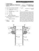
[0020] FIG. 1 depicts a top plan perspective view of a shaft collar and accompanying shaft collar pad.
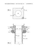
[0021] FIG. 2 depicts an elevation and cutaway view of a shaft collar pad and accompanying extended collar.
[0022] FIG. 3 depicts an exploded elevation view of a shaft collar surrounding the shaft casing.
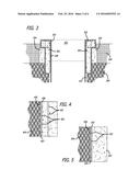
[0023] FIG. 4 depicts a lower shaft cross-sectional view of the lower shaft reinforcement of a shaft.
[0024] FIG. 5 depicts a cross-sectional view of a cast in place shaft wall for a shaft.
[0025] FIG. 6 depicts a perspective view of a shaft collar pad construction including forms and reinforcements.
[0026] FIG. 7 depicts a perspective view of a poured shaft collar.
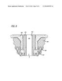
[0027] FIG. 8 depicts a side perspective view of an emergency hoist collar pad of the present invention.
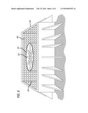
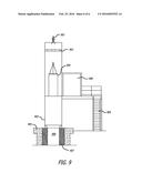
[0028] FIG. 9 depicts a side perspective view of an emergency hoist airlock platform and sheave deck, pipe section, and accompanying extended collar.
DETAILED DESCRIPTION OF THE DISCLOSURE
[0029] While the making and using of various embodiments of the present invention are discussed in detail below, it should be appreciated that the present invention provides many applicable inventive concepts that can be embodied in a wide variety of specific contexts, goods, or services. The specific embodiments discussed herein are merely illustrative of specific ways to make and use the disclosure and do not delimit the scope of the disclosure.
[0030] All publications and patent applications mentioned in the specification are indicative of the level of skill of those skilled in the art to which this disclosure pertains. All publications and patent applications are herein incorporated by reference to the same extent as if each individual publication or patent application was specifically and individually indicated to be incorporated by reference.
[0031] The present invention will now be described more fully hereinafter with reference to the accompanying drawings, which form a part hereof, and which show, by way of illustration, specific example embodiments. Subject matter may, however, be embodied in a variety of different forms and, therefore, covered or claimed subject matter is intended to be construed as not being limited to any example embodiments set forth herein; example embodiments are provided merely to be illustrative. Likewise, a reasonably broad scope for claimed or covered subject matter is intended. Among other things, for example, subject matter may be embodied as methods, devices, components, or systems. The following detailed description is, therefore, not intended to be taken in a limiting sense.
[0032] Throughout the specification and claims, terms may have nuanced meanings suggested or implied in context beyond an explicitly stated meaning Likewise, the phrase "in one embodiment" as used herein does not necessarily refer to the same embodiment and the phrase "in another embodiment" as used herein does not necessarily refer to a different embodiment. It is intended, for example, that claimed subject matter include combinations of example embodiments in whole or in part.
[0033] In general, terminology may be understood at least in part from usage in context. For example, terms, such as "and", "or", or "and/or," as used herein may include a variety of meanings that may depend at least in part upon the context in which such terms are used. Typically, "or" if used to associate a list, such as A, B or C, is intended to mean A, B, and C, here used in the inclusive sense, as well as A, B or C, here used in the exclusive sense. In addition, the term "one or more" as used herein, depending at least in part upon context, may be used to describe any feature, structure, or characteristic in a singular sense or may be used to describe combinations of features, structures or characteristics in a plural sense. Similarly, terms, such as "a," "an," or "the," again, may be understood to convey a singular usage or to convey a plural usage, depending at least in part upon context. In addition, the term "based on" may be understood as not necessarily intended to convey an exclusive set of factors and may, instead, allow for existence of additional factors not necessarily expressly described, again, depending at least in part on context.
[0034] Subterranean oil recovery platforms, similar to traditional mining, involve the formation of shafts, bores, tunnels and the like. Often they are specialized shafts for mining and other uses, such as subsurface oil recovery. Shaft mining refers to the method of excavating a vertical or near-vertical tunnel from the top down, where there is initially no access to the bottom. A shaft may be either vertical or inclined (between 45 and 90 degrees to the horizontal), although most modern mine shafts are vertical.
[0035] The most visible feature of a typical mine shaft is the headframe (or winding tower, poppet head or pit head) which stands above the shaft and houses a hoist motor. At ground level beneath and around the headframe is the shaft collar, which provides the foundation necessary to support the weight of the headframe and provides a means for personnel, material and services to enter and exit the shaft. Collars are usually massive reinforced concrete structures with more than one level. If the shaft is used for mine ventilation, a plenum space or casing is incorporated into the shaft collar to ensure the proper flow of air into and out of the mine.
[0036] Beneath the shaft collar the part of the shaft which continues into the ground is known as the shaft. At locations where the shaft meets horizontal workings there is a shaft station which allows men, materials and services to enter and exit the shaft. From the station tunnels (drifts, galleries or levels), or boreholes extend towards an ore body or reservoir.
[0037] A typical shaft lining performs several functions; it is first and foremost a safety feature preventing loose or unstable rock from falling into the shaft, then a place for shaft sets to bolt into and lastly a smooth surface to minimize resistance to airflow for ventilation. Often smaller shafts are designed to be rectangular with timber supports. Larger shafts are round and may be concrete lined. Shaft lining design is dependent on the geology of the rock which the shaft passes through, and some shafts may have several liners sections as may be required. Where shafts are sunk in highly competent rock there may be no lining, or a minimal installation of welded mesh and rock bolts. The material of choice for shaft lining is concrete which is poured behind forms. Shotcrete, fibrecrete, brick, cast iron tubing, pre-cast concrete segments have also been used. Additionally, the use of materials like bitumen and even squash balls have been required by specific circumstances.
[0038] In circumstances involving subterranean drilling platforms, such as with underground gravity drainage (UGD), an underground drilling facility is utilized where workers and equipment are present. These facilities may penetrate beneath groundwater formations. Typical shaft construction may utilize specialized liner systems to isolate the shaft operations from the surrounding formations. However, due to the presence of groundwater formations, it is necessary to ensure isolation of such formations to maintain subsurface facility habitability. Typical liners may have limitations, including joints and grouting, which may compromise essential groundwater isolation by allowing a leak path for water infiltration. In one embodiment of the present invention, a shaft collar comprising concrete is extended from the surface an impermeable shaft collar extending from a surface continuously underground below a groundwater formation into a competent rock formation for groundwater isolation from the shaft to an underground drilling facility. The extension of the collar from the surface ensures the shallow groundwater supply is protected from the inner workings of the shaft, and in return protects the shaft from groundwater inflow events, as well as hazardous or combustible gases.
[0039] For the purposes of the present invention a large diameter wellbore or shaft refers to a shaft greater than or equal to 2 feet in finished diameter, further comprising monobores, where the diameter of the shaft is uniform from the underground facility to the surface. These types of shafts are able to be structured in a continuous manner without the requirement for multiple casings or liners. However, the use of such shafts require that any perforations or intervention operations be minimized to ensure the inner diameter of the shaft is not reduced to an extent shaft operations are compromised.
[0040] The term concrete in the present invention refers to a composite material composed of water, coarse granular material (the fine and coarse aggregate or filler) embedded in a hard matrix of material (the cement or binder) that fills the space among the aggregate particles and glues them together. There are many types of concrete available, created by varying the proportions of the main ingredients below. In this way or by substitution for the cementitious and aggregate phases, the finished product can be tailored to its application with varying strength, density, or chemical and thermal resistance properties, as described more fully below.
[0041] Shotcrete is concrete (or sometimes mortar) conveyed through a hose and pneumatically projected at high velocity onto a surface, as a construction technique. Shotcrete is usually an all-inclusive term that can be used for both wet-mix and dry-mix versions. Shotcrete undergoes placement and compaction at the same time due to the force with which it is projected from the nozzle. It can be impacted onto any type or shape of surface, including vertical or overhead areas.
[0042] Aggregate consists of large chunks of material in a concrete mix, generally a coarse gravel or crushed rocks such as limestone, or granite, along with finer materials such as sand.
[0043] Cement, commonly Portland cement, and other cementitious materials such as fly ash and slag cement, serve as a binder for the aggregate. Water is then mixed with this dry composite, which produces a semi-liquid that workers can shape (typically by pouring it into a form). The concrete solidifies and hardens to rock-hard strength through a chemical process called hydration. The water reacts with the cement, which bonds the other components together, creating a robust stone-like material.
[0044] Chemical admixtures are added to achieve varied properties. These ingredients may speed or slow down the rate at which the concrete hardens, and impart many other useful properties including increased tensile strength and water resistance.
[0045] Reinforcements are often added to concrete. Concrete can be formulated with high compressive strength, but always has lower tensile strength. For this reason it is usually reinforced with materials that are strong in tension (often steel) or, with the advent of modern technology, cross-linking styrene acrylic polymers. The reinforcement is usually, though not necessarily, steel reinforcing bars (rebar) and is usually embedded passively in the concrete before the concrete sets. Reinforcing schemes are designed to increase tensile strength in the concrete. Modern reinforced concrete can contain varied reinforcing materials made of steel, polymers or alternate composite material in conjunction with rebar or not. Reinforced concrete may also be permanently stressed (in compression), so as to improve the behavior of the final structure under working loads. The most common methods of doing this are known as pre-tensioning and post-tensioning.
[0046] Mineral admixtures are also commonly utilized. The use of recycled materials as concrete ingredients has been gaining popularity because of increasingly stringent environmental legislation, and the discovery that such materials often have complementary and valuable properties. The most conspicuous of these are fly ash, a by-product of coal-fired power plants, and silica fume, a byproduct of industrial electric arc furnaces. The use of these materials in concrete reduces the amount of resources required, as the ash and fume act as a cement replacement. This displaces some cement production, an energetically expensive and environmentally problematic process, while reducing the amount of industrial waste that must be disposed of.
[0047] Chemical admixtures include accelerators which speed up the hydration (hardening) of the concrete. Typical materials used are CaCl2, Ca(NO3)2 and NaNO3. However, use of chlorides may cause corrosion in steel reinforcing and is prohibited in some countries, so that nitrates may be favored.
[0048] Retarders slow the hydration of concrete and are used in large or difficult pours where partial setting before the pour is complete is undesirable. Typical polyol retarders are sugar, sucrose, sodium gluconate, glucose, citric acid, and tartaric acid.
[0049] Air entrainments add and entrain tiny air bubbles in the concrete, which reduces damage during freeze-thaw cycles, increasing durability. However, entrained air entails a trade off with strength, as each 1% of air may decrease compressive strength 5%.
[0050] Plasticizers increase the workability of plastic or "fresh" concrete, allowing it be placed more easily, with less consolidating effort. A typical plasticizer is lignosulfonate. Plasticizers can be used to reduce the water content of a concrete while maintaining workability and are sometimes called water-reducers due to this use. Such treatment improves its strength and durability characteristics. Superplasticizers (also called high-range water-reducers) are a class of plasticizers that have fewer deleterious effects and can be used to increase workability more than is practical with traditional plasticizers. Compounds used as superplasticizers include sulfonated naphthalene formaldehyde condensate, sulfonated melamine formaldehyde condensate, acetone formaldehyde condensate and polycarboxylate ethers.
[0051] Corrosion inhibitors are used to minimize the corrosion of reinforcing steel in concrete. Bonding agents are used to create a bond between old and new concrete (typically a type of polymer) with wide temperature tolerance and corrosion resistance. Pumping aids improve pumpability, thicken the paste and reduce separation and bleeding.
[0052] The mix design depends on the type of structure being built, how the concrete is mixed and delivered, and how it is placed to form the structure. All of the above-referenced attributes may be incorporated into the term concrete or reinforced concrete for the purposes of the present invention.
[0053] It is therefore an object of the present invention to provide an extended shaft collar for purposes of protecting surrounding groundwater from shaft activity. The shaft collar extends below the surface into the competent rock zone to form an impenetrable barrier between the shaft and the surrounding formations which may include groundwater formations. For the purpose of the present invention, a shallow groundwater supply or groundwater formation means any groundwater formation which is located above a subterranean facility. A groundwater formation is an underground formation comprising groundwater. Groundwater is the water located beneath the surface in soil pore spaces and in the fractures of rock formations. A unit of rock or an unconsolidated deposit is called an aquifer when it can yield a usable quantity of water. The depth at which soil pore spaces or fractures and voids in rock become completely saturated with water is called the water table. Groundwater is recharged from, and eventually flows to, the surface naturally; natural discharge often occurs at springs and seeps, and can form oases or wetlands. Groundwater is also often withdrawn for agricultural, municipal, personal, and industrial use by constructing and operating extraction wells.
[0054] In many jurisdictions, governing bodies impose constraints on potable water supply for drinking water, irrigation, or other water use needs. These restrictions are placed upon operations which are drilling or operating through a groundwater formation and require that isolation be maintained to ensure the groundwater formation is not harmed or polluted by the subterranean operations.
[0055] In one embodiment, a shaft is excavated, upon which a flashing of exposed rock is provided which comprises fiber reinforced shotcrete for areas involving raveling ground. A panning and brattice cloth step may then be applied to the bottom of the excavated shaft. Below the extended shaft collar, a cast in place shaft lining is then set to within 50 feet of the bottom of the excavation, in order to provide protective lining for the shaft. The shaft collar is extended from the surface below the collar pad and retaining wall into the competent rock layer of the formation. The penetration through the shallow ground water formation is thus performed by a shaft collar which isolates the inner workings of the shaft from the formation inflows, and vice versa.
[0056] Turning to FIG. 1, an overhead view of the shaft borehole 105 is provided having an inner diameter 101 comprising a concrete collar and an external retaining wall 103. At the surface of the shaft collar a shaft collar pad 102 is provided which acts as a support for surface equipment. The surface equipment may comprise a headframe, hoisting equipment, and supports utilities which are run in hole to service, supply, and remove, the workings from the subterranean drilling facility. Reinforcing 104 is provided for the shaft collar 101, shaft collar retainer wall 103 and shaft collar pad 102.
[0057] The shaft collar and accompanying shaft collar pad is designed to accommodate the weight and support necessary for the surface equipment. The design and function of the surface equipment, and the resulting shaft collar pad which supports such equipment is a function of several factors using standard engineering methods associated with strength of materials, constructability, and long-term operation. These factors include the sizes and weights of the headframe, hoisting systems (which may include a personnel hoist (or skip hoist), winch hoist, utility supports, and the proposed weight requirements for the respective capacities of the above. Further, these calculations are made in light of the service parameters of the shaft, budget, and time. Service parameters may include space limitations (or requirements) including the size of the shaft based on the size of equipment which is run in hole. By way of a non-limiting example, for a subterranean drilling environment, the winch hoist capacity factors in the maximum weight necessary for the equipment (such as a drilling rig) to be send underground to the underground facility. Further the skip hoist is further designed to carry a required number of personnel. It is often required that such facilities have performance requirements for emptying and accounting the facility within a required timeframe, such as 30 minutes. These regulations further account for the size of equipment needed, taking into account the main shaft and any existing ventilation or emergency shafts, in then calculating the size, weight and support necessary for the shaft collar pad.
[0058] FIG. 2 presents a side perspective view of the entire shaft collar as extended into the shaft, connecting to the shaft liner below a shallow groundwater formation 205. The shaft collar pad 203 is extended at the surface to accommodate surface equipment the shaft collar extends downward and is supported externally by the retaining wall 206 located external to the inner shaft collar. The retaining wall 206 further supports the extended shaft collar pad 203. The retainer wall 206 further extends underground to an extent substantially supporting the shaft collar through the shallow groundwater formation 205. The shaft collar further extends along the internal shaft 202 into a competent rock formation 204 and transitions within the competent rock formation 204 into a shaft liner 207. The shaft liner 207 may employ typical cast-in-place or pre-cast components and may further comprise an inner shaft liner 209 which extends substantially the length of the shaft to the underground drilling facility. Overbreak zones 208 in the competent rock formation are managed with various techniques described below (see FIG. 4).
[0059] In another embodiment, the upper portion of the shaft collar as shown in FIG. 3 is extended below the ground as a support for the headframe. An inner diameter shaft treatment 302 may comprise a steel casing, such as 3/4'' steel. The extended shaft collar 303 further includes reinforcement 308 which extends through the shallow groundwater formation 305 into the competent rock formation 306. For exemplary purposes, the upper portion of the shaft collar 303 extends between the retainment wall to approximately sixteen feet into the competent rock formation. The extended collar then transitions to a protective casing 307 which extends to the bottom of the shaft 301, forming an impenetrable barrier, thus preventing the transfer of products of the shaft into ground formations and, alternatively, preventing the inflow of products of the ground formation into the shaft, such as groundwater.
[0060] In another embodiment, the present invention provides an impermeable barrier of steel and concrete to isolate the work area of the shaft from a groundwater formation. In yet another embodiment, the groundwater isolation prevents the inflow of shaft activities and produced materials into the shallow groundwater formations. In another embodiment, the present invention isolates the supply air flow from hazardous formation gases and fluids. The extended shaft collar may be used in connection with other water and inflow drainage capabilities necessary for removing potential inflows present at the external portions of the shaft liner.
[0061] In one embodiment, the extended shaft collar of the present invention is utilized in heavy civil construction projects involving the formation of a shaft. In another embodiment, the extended shaft collar is utilized for oil production wells. In yet another embodiment, the extended shaft collar is utilized in subsurface oil recovery platforms and oil mining platforms.
[0062] In a further embodiment, a method for providing an extended shaft collar is provided by having a shaft collar platform extend to competent rock formations following the excavation of a shaft wherein the collar pad is connected to a vertical collar below the pad extending downward into the shaft. The extended shaft collar transitions to the shaft lining formation below the known groundwater formation depth. Such transition is to shaft liner systems typical in the art, and may further include aspects as set forth in FIG. 4, which provides a lower shaft reinforcement cross sectional view. Reinforcement bar 401 is utilized in connection with a concrete liner which may further comprise cast-in-place concrete sections. Additional wire mesh componentry may be added and included in connection with panning and brattice cloth 403, which may be used for stabilizing the rock formation 404 and potential overbreak zones 405. In situations where raveling rock is encountered, such systems comprising a panning and brattice cloth 403, welded wire mesh 406 and any required spacers 402 to separate the wire mesh from the rock surface. In the event raveling rock is encountered, an initial coat of fiber-reinforced shotcrete is applied. Following the application of the shotcrete, if necessary, the panning and brattice cloth 403, the welded wire mesh with spacers 402 and reinforced concrete of various types are applied to complete the lining. This lining utilizes other water drainage features external to the inner diameter of the shaft to collect and remove water inflows. The shaft liner continues downward from the extended collar to the bottom of the shaft.
[0063] In another embodiment, the cast-in-place shaft wall of FIG. 5 may be applied to the shaft liner. A single cast-in-place concrete liner 503 may be incorporated. Spacers 501 accompanying a welded wire mesh 502 may be utilized to hold the welded wire mesh 502 off the rock surface 506. If raveling rock is encountered from the rock formation 504, a flash coat of shotcrete, for example, may be applied 505. The shotcrete may be fiber reinforced. The shotcrete coating may further include panning and brattice cloth coverage.
[0064] In another embodiment, the shaft collar comprises a concrete pad at the surface for purposes of supporting surface equipment and piping support assemblies. FIG. 6 provides a view of the shaft 601 having temporary bracing material 604 within a pad formed by forming 603 on the outer edge of the shaft collar pad and utilizing reinforcement bars 602 within the area where concrete is to be poured. The shaft collar then extends below the pad and within a retainment wall (see FIG. 1) comprised of concrete. The lower extended portion of the collar extends below the retainment wall and into the competent rock. The extended collar then transitions to the shaft lining assembly for extending throughout the remaining portion of the shaft. FIG. 7 provides a perspective view of a finished shaft collar pad 702, wherein the shaft collar 701 is positioned at or near the center of the shaft collar pad 702. The forms 703 may then be removed for completion of the construction. The temporary shaft supports 704 may further be removed.
[0065] In another embodiment, the shaft collar of the present invention is utilized in subterranean drilling operations involving the formation of an emergency shaft. The extended emergency shaft collar is utilized in subsurface oil recovery platforms and oil mining platforms, including for emergency shafts constructed for emergency use, ventilation, and explosion relief. In addressing such critical functions as an emergency shaft, including ventilation, an additional steel liner is incorporated to ensure complete liquid and gaseous isolation from the shaft in consideration of the supply air aspects of the emergency shaft.
[0066] FIG. 8 provides a side perspective view of an exemplary emergency shaft, which may further serve as a ventilation shaft, providing airflow downhole via surface-based ventilation equipment. The shaft 801 is provided an inner steel casing 802, which further increases the gas and liquid impermeability to ensure critical air supply and emergency function. The steel liner serves as an additional protective liner that is vapor resistant to prevent hazardous gas infiltration (such as methane) into the shaft, including resisting any formation water. This protective liner is preferably steel, although other vapor resistant materials may be used provided the other materials are able to withstand the other load and structural requirements of the shaft. The protective liner in a ventilation shaft (providing supply air) must further be vapor resistant to ensure the supply air remains fresh and free from contamination. The thickness of the steel liner is factored by strength and corrosion needs. In one embodiment, the thickness of the steel liner may be up to two inches thick. In another embodiment, the thickness of the steel liner is one inch. In yet another embodiment the thickness of the steel liner is 3/4-inch. In another embodiment, the thickness of the steel liner is 1/2 A inch. In further considering the thickness of the steel liner, the inner diameter of the shaft for functional use is critical. Further, determinations of the corrosion resistance necessary, in the event of brackish water exposure or other harsh environments is critical to factor in to the long term life service of the shaft.
[0067] The extended collar 803 is brought to the surface absent any expanding concrete pad to ensure continuity in the collar for protective features of the emergency shaft. The emergency shaft collar pad 804 is thus positioned external to the emergency shaft steel liner 802 and emergency shaft collar 803. The emergency shaft pad 804 is then designed in accordance with the supporting various surface equipment having the above-reference criteria, and further includes emergency hoist equipment, ventilation equipment, and related headframe and airlock systems typical of an emergency shaft. The emergency shaft 801 then continues downward accompanied by the extended shaft collar 803 below the groundwater formation 806 and into the competent rock formation 805. Because of the orientation of the emergency shaft collar pad 804 external to the emergency shaft collar 803, the retainment wall 807 is thus positioned below both the emergency shaft collar 803 and emergency shaft collar pad 804.
[0068] FIG. 9 provides another perspective view of the exemplary emergency shaft having associated equipment supported by the emergency shaft collar. The emergency shaft collar 907 is brought the surface as indicated in FIG. 8. The emergency collar pad 905 is truncated for purposes of FIG. 9, but is extended as needed for accommodating the needed hoist and ventilation equipment. A ventilation and emergency hoist facility 903 is positioned over and supported by the emergency shaft collar 907. The emergency hoist system comprises a hoist elevator 904 for workers and equipment and related equipment, such as a wire rope sheave 901 for driving the hoist system. An explosion relief panel 902 may be further provided. Worker access 908, 909, may be further provided and supported.
[0069] Those skilled in the art will recognize that the methods and systems of the present invention may be implemented in many manners and as such are not to be limited by the foregoing exemplary embodiments and examples. Furthermore, the embodiments of methods presented and described as flowcharts in this disclosure are provided by way of example in order to provide a more complete understanding of the technology. Disclosed methods are not limited to the operations and logical flow presented herein. Alternative embodiments are contemplated in which the order of the various operations is altered and in which sub-operations described as being part of a larger operation are performed independently.
[0070] While various embodiments have been described for purposes of this disclosure, such embodiments should not be deemed to limit the teaching of this disclosure to those embodiments. Various changes and modifications may be made to the elements and operations described above to obtain a result that remains within the scope of the systems and processes described in this disclosure.
User Contributions:
Comment about this patent or add new information about this topic:
Images included with this patent application:
 |  |
 |  |
 |  |
 |
| Similar patent applications: | |
| Date | Title |
|---|---|
| 2015-05-07 | Shaker screen assembly |
| 2015-11-05 | Wellhead safety valve assembly |
| 2015-11-26 | Subsea connector assembly |
| 2016-05-19 | Downhole umbilical release assembly |
| 2015-10-22 | Subsea sensor assemblies |
| New patent applications in this class: | |
| Date | Title |
|---|---|
| 2022-05-05 | Locking pin tool for use with a locking pin of a wellhead |
| 2017-08-17 | Completion deflector for intelligent completion of well |
| 2017-08-17 | Powered slip actuation |
| 2016-09-01 | Casing window assembly |
| 2016-09-01 | Flow distribution assemblies with shunt tubes and erosion-resistant fittings |
| Top Inventors for class "Wells" | |
| Rank | Inventor's name |
|---|---|
| 1 | Michael L. Fripp |
| 2 | Jean Marc Lopez |
| 3 | Michael H. Johnson |
| 4 | Jørgen Hallundbaek |
| 5 | Dennis P. Nguyen |