Patent application title: Fan Forced Oil Filter Cooler
Inventors:
Benjamin Daniel Boynton (Tyler, TX, US)
IPC8 Class: AF01M500FI
USPC Class:
123196AB
Class name: Internal-combustion engines lubricators heating and cooling
Publication date: 2016-02-18
Patent application number: 20160047282
Abstract:
The current invention consists of a fan forced heat sink oil cooler which
attaches to the end of an oil filter. Typically, the invention will be
used for the cooling of engine oil on an air cooled motorcycle. The
current invention utilizes a housing attached to a fan forced, finned
heat sink to remove heat from the engine oil expelling engine heat to the
ambient air. The invention externally clamps on the oil filter which
effectively turns the oil filter into an oil cooler. The design provides
engine oil cooling during periods of idle or slow speeds as well as while
the vehicle is in motion. The new design has remedied the necessity of
penetrating and changing the existing oil route thus avoiding harm to the
engine due to malfunction of an oil cooler. Another advantage to this
design is simple and quick installation with ordinary knowledge and
skill.Claims:
1-3. (canceled)
4. An oil filter cooler for an internal combustion engine that circulates engine oil through an oil filter, the oil filter cooler comprising: a housing having at one end a cylindrical collar configured to receive and be releasably attachable to a closed free end of the oil filter, and at another end a heat sink further comprising a body with a cylindrical bore surrounded by a plurality of radially directed, circumferentially spaced fins disposed in fixed relation to the cylindrical collar and the cylindrical bore; and a fan unit attached to the housing and disposed inside the cylindrical bore, the fan unit comprising an electric motor, a plurality of fan blades rotatable inside the cylindrical bore by a shaft driven by the electric motor, and wires providing electrical energy to the electric motor; whereby heat is initially transferred to the oil filter by the engine oil circulated through the oil filter and is subsequently dissipated from the oil filter through the heat sink body and fins of the oil filter cooler and by the fan unit that is operable to force ambient air past the heat sink body and fins.
5. The oil filter cooler of claim 4 wherein the cylindrical collar of the housing further comprises a notch or split to facilitate attachment to the closed free end of the oil filter.
6. The oil filter cooler of claim 4, further comprising a clamp band disposed around the cylindrical collar of the housing for use in attaching the housing to the closed free end of the oil filter.
7. The oil filter cooler of claim 6 wherein the clamp band comprises a screw adjustment.
8. The oil filter cooler of claim 4, further comprising a heat transfer material disposed inside the housing and configured to improve heat transfer between the oil filter and the housing.
9. The oil filter cooler of claim 4 wherein the electric motor is a high-speed 12-volt motor.
10. The oil filter cooler of claim 4 wherein the housing is made of a material selected from the group consisting of steel, aluminum, and any other metal that conducts heat well.
11. The oil filter cooler of claim 4 wherein the heat sink is made of a material selected from the group consisting of aluminum or copper.
12. The oil filter cooler of claim 8 wherein the heat transfer material is a thermally conductive paste.
13. The oil filter cooler of claim 4 wherein the internal combustion engine is an air-cooled engine.
14. The oil filter cooler of claim 4 wherein the internal combustion engine is a motorcycle engine.
Description:
BACKGROUND OF THE INVENTION
[0001] 1. Field of the Invention
[0002] The current invention relates to an oil filter cooler. Specifically, the current invention relates to an oil cooler for an internal combustion engine, such as a motorcycle's air cooled engine.
[0003] 2. Description of the Related Art
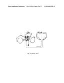
[0004] An air cooled motorcycle engine often does not have an external oil cooler when manufactured. For motorcycles that have an oil cooler, oil is pumped through the engine, oil filter, and then cooler oil is returned to the engine. The most frequently used type of motorcycle oil cooler is a square or rectangular structure placed on the front frame of the motorcycle. FIGS. 7-10 illustrate other prior art oil coolers and the mounting position on the motorcycle. For more information about the structure and function of a motorcycle cooler, see U.S. Pat. Nos. 4,295,964; 4,662,470; 5,244,036 and 5,901,808 and is incorporated herein.
[0005] Drawbacks to conventional oil cooler systems include more expense, significant additional installation difficulty, and the requirement of puncturing the oil system so oil will flow through the added oil cooler (see FIG. 7-19 and FIG. 22). These drawbacks occur in U.S. Pat. Nos. 4,295,964; 4,662,470; 5,244,036; 5,901,808, 4,690,236; 5,307,865; 5,363,823; 5,887,561; 5,901,808; 6,871,628; 6,994,150; 6,955,150; 8,267,054 and is incorporated herein.
[0006] More importantly, traditional oil coolers without added fans are ineffective during idling stops at traffic lights or moving at low speeds. This reduction in airflow leads to engine overheating resulting in engine damage. Traditional oil coolers also are often mounted underneath the motorcycle and can be subject to road debris. This current invention mounts on the oil filter and will be protected from many of the road hazards of conventional oil coolers. Damage to typical oil coolers can lead to flow blockage and overheating of the engine due to stopped, or reduced oil flow. If this current invention's fins become clogged, the fan stops or becomes dislodged, resulting in no disruption of the stock oil flow system.
[0007] U.S. Pat. No. 5,740,772 (see FIG. 20-21) has a slip-on attachable fin set to mount on the oil filter. A similar advantage to the current invention is that this does not puncture the oil path. However, the drawbacks are that without fans, fins are ineffective during idling while stopped at traffic lights or moving at low speeds. Further, the fins have a much smaller surface area to dissipate heat than the current invention. U.S. Pat. No. 5,363,823 (see FIG. 22) installs between oil filter and oil; however, this cooler does not provide forced air for idling and low speed travel. Therefore, this invention is ineffective for idling and low speeds which is often the cause of overheating of air cooled motors.
[0008] Esthetics is often important to motorcycle riders. The outward beauty of a motorcycle is often jeopardized by bulky or unsightly oil coolers. This invention slips on the end of the oil filter and has attractive circular flat black heat sink and fins with mil finishing enhancing the function and the look of the motorcycle.
[0009] The installer simply applies the thermal paste, places invention on the oil filter, and tightens clamp with a screwdriver or nut driver. Lastly, two easily concealed thin wires to power the 12 volt electric fan are installed to the motorcycle's electrical system. On cruisers, it is usually connected to the accessory switch on the dash. Sport bikes will run a wire to the battery with an inline fuse and switch. The deluxe model for this invention includes a thermo-switch to turn the 12 volt fan motor on and off according to a predetermined oil temperature.
BRIEF DESCRIPTION OF THE DRAWINGS
[0010] The current invention will be more readily understood with the detailed drawings described herein below. Additionally, the accompanying drawings are shown via illustration only and are not limits of the current invention and wherein:
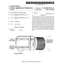
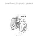
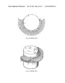
[0011] FIG. 1 is a front and top view of the current invention;
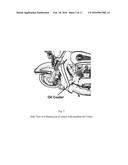
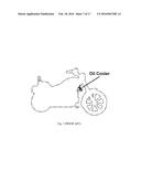
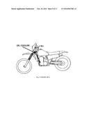
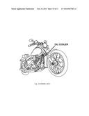
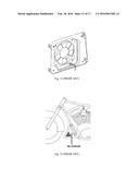
[0012] FIG. 2 shows the location of the current invention when installed on a motorcycle.
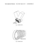
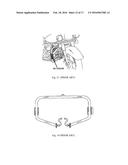
[0013] FIG. 3 is a side view of the current invention indicating the heat flow from the engine to the housing, heat sink and to the ambient air via fan forced air;
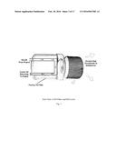
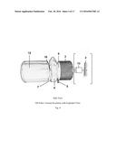
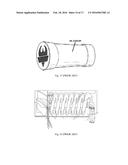
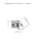
[0014] FIG. 4 is a side view of a factory oil filter, heat transfer housing, clamp, and heat sink in accordance with the current invention. The exploded view shows a 12 volt motor and connected fan imbedded inside the heat sink fins and mounted on the heat sink base;
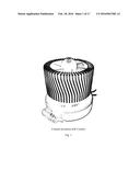
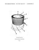
[0015] FIG. 5 is a top and front view with numbers indicating a description of the parts;
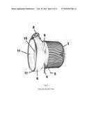
[0016] FIG. 6 is a side view with numbers indicating a description of the parts;
[0017] FIG. 7 is a side view of a motorcycle with an oil cooler in accordance with a first embodiment of the prior art;
[0018] FIG. 8 is a front perspective view of an oil cooler in accordance with a second embodiment of the prior art;
[0019] FIG. 9 is a side perspective view of an oil cooler in accordance with a third embodiment of the prior art;
[0020] FIG. 10 is a front view of a motorcycle with an oil cooler in accordance with a fourth embodiment of the prior art;
[0021] FIG. 11 is a front perspective view of a motorcycle with an oil cooler in accordance with the fifth embodiment of the prior art;
[0022] FIG. 12 is a backside view of a primary drive cover of the motorcycle engine of FIG. 11 in accordance with a fifth embodiment of the prior art;
[0023] FIG. 13 is a front view of the engine guard, which includes the oil cooler; in accordance with the sixth embodiment of the prior art;
[0024] FIG. 14 is a front descriptive and perspective view of an oil cooler in accordance with the sixth embodiment of the prior art;
[0025] FIG. 15 is a front perspective view of the oil cooler fan of FIG. 16 in accordance with the seventh embodiment of the prior art;
[0026] FIG. 16 is a side view of the oil cooler in accordance with the seventh embodiment of the prior art;
[0027] FIG. 17 is a front view of an oil cooler in accordance with the eight embodiment of the prior art;
[0028] FIG. 18 is a side view cutout of and oil cooler in accordance with the eight embodiment of the prior art;
[0029] FIG. 19 is a side perspective view of an oil cooler in accordance with the ninth embodiment of the prior art;
[0030] FIG. 20 is a top view of an oil cooler in accordance with the tenth embodiment of the prior art.
[0031] FIG. 21 is a side and top view of an oil cooler in accordance with the tenth embodiment of the prior art.
[0032] FIG. 22 is a side view of an oil cooler in accordance with the eleventh embodiment of the prior art.
DETAILED DESCRIPTION OF INVENTION
[0033] The current invention is currently more fully described hereinafter with references to the associated drawings. This invention may be embodied in many different forms and should not be understood to mean limited to the drawings set forth herein. These drawings are provided so the disclosure will be thorough and complete and fully convey the intent of the invention. The terminology used in this presentation is for the purpose of describing drawings and components only and is not intended to limit the invention. Further, that the terms, commonly used in dictionaries, should be interpreted consistently with the context of the specification. Moreover, the drawing or text should not be interpreted in a more formal sense or overly idealized unless expressly defined herein.
[0034] This invention attaches to the oil filter and conducts heat using the oil filter as an oil cooler via thermal paste, heat sink and 12 volt fan as one unit. Having an oil cooler that does not puncture the oil lines to install has advantages. Oil will not be lost or potentially leak during installation. This invention is easier to install, costs less, and greatly reduces labor time/cost to install. Additionally, the oil cooler is in the front for increased air flow while the motorcycle is at rest or in motion.
[0035] FIG. 1 shows the current invention;
[0036] FIG. 2 shows side view of a motorcycle with installed current invention;
[0037] FIG. 3 shows a graphical and verbal description of air cooled engine thermal processes and functioning of current invention. FIG. 3 shows the oil filter connected to current invention. The fan and fan motor are not visible because the fan and motor are located inside the heat sink. Therefore, air can be propelled at high speed through the fins to transfer heat out of the heat sink into the air. This drawing shows the oil being pumped from the engine by the factory oil pump into the oil filter. The heat from the oil is transferred into the heat sink and then into the fins. The 12 volt electric motor turns the fan blades at high speed to force air through the fins and transfer heat from the higher temperature to the lower ambient air;
[0038] FIG. 4 shows the current invention. This invention includes heat transfer material, heat transfer housing, heat sink, 12 volt motor, and fan. The heat transfer housing can be made out of aluminum, steel or any metal that conducts heat well. Diameter of the housing is approximately 31/8 inches. The housing clamps on the oil filter with approximately 3/4 of an inch or more covering the sides of the oil filter. The height of the invention is typically between 31/4 inches and 37/8 inches. The heat sink usually ranges in height from 2 to 21/2 inches with a diameter of about 25/8 inches. Heat sink fin numbers differ with a typical number at 60 fins. However, dimensions and numbers can vary depending on available space and amount of cooling required. The heat sink (aluminum or copper) connects to the oil filter with thermal paste (heat transfer material) in between oil filter and heat sink. The fan located inside, or in front of heat sink removes heat from the heat sink to the ambient air. The purpose of the housing is to hold the heat sink to the oil filter and to aid in heat transfer. The clamp tightens the housing to the oil filter so during vibration of motor, the invention does not become unattached.
[0039] FIG. 5 shows the top and front view of the current invention including the fan; and
[0040] FIG. 6 shows the side and bottom view of the current invention.
BRIEF SUMMARY OF THE INVENTION
[0041] It is the purpose of this invention to address one or more of the shortcoming of the prior art engine oil coolers and/or of the applicant's respected needs in the art. The current invention presents a cooler for an engine such as a motorcycle without the need for penetrating the existing oil route of an engine or adding expensive and cumbersome parts. The invention effectively turns the oil filter into fan forced oil cooler. This system provides supplemental oil cooling via increased surface area and fan forced ventilation to the oil filter. Therefore, the design cools the engine at idle and low speeds very easy and at a fraction of the cost of existing oil coolers. This invention is more easily installed with fewer parts, and more readily incorporates this cooler into the original design of the motorcycle, or other motorized vehicles. Additionally, it improves the function without distracting from the original aesthetics of the motorcycle. This device transfers heat from the engine oil that is pumped by the motorcycle's factory oil pump into the oil filter. Then the device dissipates the heat into the ambient air. Further, the device cools the engine without penetrating the existing oil system or rerouting the factory oil lines. The new invention is also protected from road debris because it is located inside the front of the motorcycle on the oil filter protected by the engine and frame.
TABLE-US-00001 REFERENCES CITED 2,781,859 February 1957 Warren 4,295,964 October 1981 Preisler 4,662,470 May 1987 Fujisawa et al. 5,244,036 September 1993 Michl 4,662,470 May 5, 1987 Fujisawa 4,690,236 August. 1, 1987 Shinozaki 5,307,865 May 3, 1994 Inagaki 5,363,823 Nov. 15, 1994 Gittlein 5,740,772 Apr. 21, 1998 Bluma 5,887,561 March, 1999 Spurgin 5,901,808 May 1999 Swenson et al. 6,871,628 March 2005 Tauer 6,955,150 October 2005 Moss 6,994,150 February 2006 Kline 8,267,054 September 2002 Maeda et al.
REPRESENTATIVE NUMBER KEY
[0042] 1. Fan body
[0043] 2. Fan blades
[0044] 3. Heat sink fins
[0045] 4. Motor shaft
[0046] 5. Wires to 12 volt motor
[0047] 6. Clamp band
[0048] 7. Housing (covering the top of the oil filter)
[0049] 8. Adjustment to tighten clamp and housing to oil filter
[0050] 9. Heat sink body
[0051] 10. Thermal transfer material
[0052] 11. Notch in housing so clamp can tighten housing to oil filter
[0053] 12. Oil filter
[0054] 13. High speed 12 volt motor
User Contributions:
Comment about this patent or add new information about this topic:
Images included with this patent application:
 |  |
 |  |
 |  |
 |  |
 |  |
 |  |
 |  |
 |  |
 |  |
| Similar patent applications: | |
| Date | Title |
|---|---|
| 2016-04-14 | Cooling system for charge air cooler |
| 2015-11-26 | Apparatus and method for supplying fuel using egr cooler |
| 2016-05-19 | Mechanical system forming a cam follower or a rocker arm |
| 2015-10-29 | Bearing frame or cylinder head cover |
| 2015-12-24 | Motor vehicle solenoid for a starter motor |
| New patent applications in this class: | |
| Date | Title |
|---|---|
| 2016-01-14 | Heat-insulated system for lubricating rotating and oscillating components of a motor vehicle |
| 2015-10-29 | Preheating apparatus and method for the installation of a preheating apparatus |
| 2015-04-23 | Method and arrangement for controlling transmission oil temperature |
| 2015-03-19 | Oil property management system and method for internal combustion engine fuel economy and minimum wear rates |
| 2014-07-03 | Oil pump for vehicle |
| Top Inventors for class "Internal-combustion engines" | |
| Rank | Inventor's name |
|---|---|
| 1 | Ross Dykstra Pursifull |
| 2 | Gopichandra Surnilla |
| 3 | Joseph Norman Ulrey |
| 4 | Thomas G. Leone |
| 5 | Chris Paul Glugla |