Patent application title: MAGNETIC RESONANCE IMAGING METHOD USING T2* MAPPING BASED ON ECHO PLANAR IMAGING
Inventors:
Jun-Young Chung (Incheon, KR)
Hyun Wook Park (Daejeon, KR)
Hyun Wook Park (Daejeon, KR)
Ye-Ji Han (Daejeon, KR)
IPC8 Class: AG01R3350FI
USPC Class:
324309
Class name: Particle precession resonance using a nuclear resonance spectrometer system to obtain localized resonance within a sample
Publication date: 2016-02-11
Patent application number: 20160041244
Abstract:
A flipped fitting method that performs a flipped curve fitting on a
maximum of 256 MRI images obtained at different echo times using an EPI
image which obtains a plurality of MRI images at a plurality of different
echo times within a TR period after application of an excitation RF
pulse. Then, T2* values are fitted based on a sufficient amount of
acquired TE images, such that it is possible to provide much more
accurate T2* values than these provided by underestimated or
overestimated fitting by the existing method which is based on only 12
images and to obtain rapid and accurate data without nerve stimulation or
acoustic noise. Further, the flipped fitting method is more suitable and
accurate for showing the real T2* values.Claims:
1.-12. (canceled)
13. A method for acquiring an image using a magnetic resonance imaging system, comprising: applying an excitation RF pulse; obtaining a plurality of MRI images at a plurality of different echo following application of the excitation RF pulse; and performing a flipped curve fitting on the plurality of MRI images.
14. The method of claim 13, wherein a sinusoidal-shaped readout gradient is applied during the obtaining of the plurality of MRI images.
15. The method of claim 13, wherein a trapezoidal-shaped readout gradient is applied during the obtaining of the plurality of MRI images.
16. The method of claim 13, wherein the number of the plurality of MRI images is 256.
17. The method of claim 13, wherein an analog to digital converter for data collection signal is kept in an on state during the obtaining of the plurality of MRI images.
18. A method for acquiring an image using a magnetic resonance imaging system, comprising: applying an excitation RF pulse; and applying the excitation RF pulse and then obtaining a plurality of MRI images at a plurality of different echo times, wherein a continuous readout gradient is applied during the obtaining of the plurality of MRI images.
19. The method of claim 18, wherein the continuous readout gradient has a sinusoidal shape.
20. The method of claim 16, further comprising: after the obtaining of the plurality of MRI images, performing a flipped curve fitting on the plurality of MRI images.
21. A method for acquiring an image using a magnetic resonance imaging system, comprising: applying an excitation RF pulse; and applying the excitation RF pulse and then obtaining a plurality of MRI images at a plurality of different echo times, wherein an analog to digital converter for data collection signal keeps an on state during the obtaining of the plurality of MRI images.
22. The method of claim 20, further comprising: after the obtaining of the plurality of MRI images, performing a flipped curve fitting on the plurality of MRI images.
23. The method of claim 13, further comprising: obtaining a navigator echo between the applying of the excitation RF pulse and the obtaining of the plurality of MRI images.
24. The method of claim 13, wherein the plurality of MRI images constructs a pseudo k-space in which a series of two-dimensional images are continued, depending on an echo index.
25. The method of claim 18, further comprising: obtaining a navigator echo between the applying of the excitation RF pulse and the obtaining of the plurality of MRI images.
26. The method of claim 21, further comprising: obtaining a navigator echo between the applying of the excitation RF pulse and the obtaining of the plurality of MRI images.
27. The method of claim 18, wherein the plurality of MRI images constructs a pseudo k-space in which a series of two-dimensional images are continued, depending on an echo index.
28. The method of claim 21, wherein the plurality of MRI images constructs a pseudo k-space in which a series of two-dimensional images are continued, depending on an echo index.
Description:
TECHNICAL FIELD
[0001] The present invention relates to an imaging method implemented in a magnetic resonance imaging (MRI) system, and more particularly, to a magnetic resonance imaging method using T2* mapping based on echo planar imaging (EPI).
BACKGROUND ART
[0002] There are various diagnostic imaging systems such as X-ray, CT, ultrasonic wave, RI image, MRI, and so on. Since the MRI is not harmful to a human body as compared with other diagnostic imaging systems and provides images of the characteristics of structure material inside a human body, the MRI is a very important measuring apparatus in clinical practice.
[0003] The MRI apparatus may acquire data on parameters such as spin density, T1, T2, chemical shift, magnetization transfer, chemical exchange saturation transfer, blood stream and spectroscopy, which are unique information on the body, and may acquire various types of body images based on the parameter information.
[0004] EPI, which is a high-speed photographing technique capable of acquiring spatial frequency information required for image construction by one radio frequency (RF) pulse within a TR period, is one of the most rapid pulse sequences which are currently being commercialized, and is appropriate for images which are sensitive to a motion and require a fast temporal resolution, such as perfusion images, diffusion images, functional images, and the like.
[0005] However, since the EPI method fills the entire K-space within a TR period, there is geometric distortion in the image and therefore a distorted image may be easily obtained.
[0006] Further, the EPI method acquires data for one image within about 100 ms and therefore requires much more advanced hardware than that required for a general apparatus. That is, to sample data within the short period of time, there is a need to sufficiently widen and expand the receiving bandwidth, the maximum amplitude of a gradient magnetic field needs to be large, and a strong gradient magnetic field of 10 m T/m or more is generally required. Further, however the strong gradient magnetic field is applied, when a rise time up to the maximum amplitude is long, an image may not be obtained quickly, and therefore a gradient magnetic field apparatus having a slew rate of about 200 to 250 T/ms is required to increase the gradient magnetic field to the maximum amplitude within a short period of time. Further, the data is generated very rapidly in the EPI method, and therefore a high speed receiving apparatus capable of sampling at a rapid speed is required and a large amount of data needs to be processed within a short period of time, and therefore a sufficient amount of RAM is required.
[0007] However, the EPI image is deteriorated more than other pulse sequences in terms of a current resolution or contrast, and therefore is not used in a routine method.
[0008] Meanwhile, T2* relaxation refers to the decay of transverse magnetization caused by a combination of spin-spin relaxation magnetic field inhomogeneity.
[0009] A multi-echo gradient-echo pulse sequence, which is often used for acquisition of images to perform T2* mapping, needs a long scan time and commercialized sequences have limitations, including the number of echoes (a maximum of 12), memory capacity, and the dependency of the fitting functions.
DISCLOSURE
Technical Problem
[0010] The present invention is made by recognizing at least any one of the demands or problems which occur in the related art as described above.
[0011] An aspect of the present invention provides a method of acquiring an accurate T2* map using EPI.
[0012] Another aspect of the present invention provides an echo planar imaging method with full echoes up to 256.
Technical Solution
[0013] The embodiment of the present invention performs flipped curve fitting on a maximum of 256 MRI images obtained at different echo times using a method for acquiring an EPI image, which applies an excitation RF pulse and subsequently obtains a plurality of MRI images at a plurality of different echo times. In the process of obtaining the plurality of MRI images, a continuous readout gradient such as a sinusoidal-shaped readout gradient may be applied and an analog to digital converter for data collection signal may be kept in an on state.
[0014] According to one aspect of the present invention, there is provided a method for acquiring an image using a magnetic resonance imaging system, including: applying an excitation RF pulse; obtaining a plurality of MRI images at a plurality of different echo times following application of the RF pulse; and performing a flipped curve fitting on the plurality of MRI images.
[0015] According to another aspect of the present invention, there is provided a method for acquiring an image using a magnetic resonance imaging system, comprising: applying an excitation RF pulse; obtaining a plurality of MRI images at a plurality of different echo times following application of the RF pulse, wherein in the process of obtaining the plurality of MRI images, a continuous readout gradient is applied.
[0016] According to still another aspect of the present invention, there is provided a method for acquiring an image using a magnetic resonance imaging system, comprising: applying an excitation RF pulse; and applying the excitation RF pulse and then obtaining a plurality of MRI images at a plurality of different echo times, wherein in the process of obtaining the plurality of MRI images, an analog to digital converter for data collection is kept in an on state.
[0017] The readout gradient may have a sinusoidal shape or a trapezoidal shape, and a navigator echo may be obtained between the applying of the excitation RF pulse and the obtaining of the plurality of MRI images.
[0018] The plurality of MRI images may construct a pseudo k-space in which a series of two-dimensional images are arranged according to the echo index.
Advantageous Effects
[0019] According to the method for acquiring an MRI image in accordance with the embodiments of the present invention, the T2* values are fitted based on a sufficient amount of acquired TE images, and therefore it is possible to provide more accurate T2* values than those provided by underestimated or overestimated fitting by the existing method which is based on only 12 images.
[0020] Further, the method for acquiring an MRI image in accordance with the embodiment of the present invention may rapidly and accurately acquire data without a nerve stimulation or acoustic noise and the flipped fitting method which is used in the embodiment of the present invention may more appropriately and accurately calculate the T2* value.
DESCRIPTION OF DRAWINGS
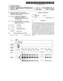
[0021] FIG. 1 is a diagram illustrating a pulse sequence which is used in a method for acquiring an MRI image according to an embodiment of the present invention.
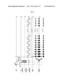
[0022] FIG. 2 is a diagram illustrating a pseudo k-space formed by the method for acquiring an MRI image according to the embodiment of the present invention.
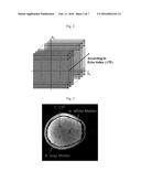
[0023] FIG. 3 is a diagram illustrating three regions of interest in a brain.
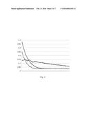
[0024] FIG. 4 is a graph of recorded values for each region of interest of FIG. 3.
[0025] FIG. 5 is a diagram illustrating a fitted curve to original data flipped according to the method of the embodiment of the present invention for each region of interest of FIG. 3.
[0026] FIGS. 6 to 8 are diagrams illustrating a pulse sequence which is used in a method for acquiring an MRI image according to another embodiment of the present invention.
BEST MODE
[0027] Hereinafter, a method for acquiring an image using a magnetic resonance imaging system according to an embodiment of the present invention will be described in detail with reference to the accompanying drawings. However, repeated descriptions and detailed descriptions related to well-known functions or configurations will be omitted herein in order not to unnecessarily obscure the subject matter of the present invention.
[0028] The configuration of an MRI system to which the present invention is applied is well known and therefore is omitted herein.
[0029] The method for acquiring an MRI image according to the embodiment of the present invention performs a flipped curve fitting on a plurality of MRI images using a method for acquiring an EPI image which applies an excitation RF pulse and then obtains the plurality of MRI images at a plurality of different echo times.
[0030] As a frequency selection readout gradient for obtaining the plurality of MRI images, for example, a continuous readout gradient such as a sinusoidal-shaped readout gradient may be applied and an analog to digital converter for data collection signal while the MRI images are acquired needs to be kept at an on state.
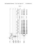
[0031] FIG. 1 is a diagram illustrating a pulse sequence which is used in a method for acquiring an MRI image according to an embodiment of the present invention.
[0032] In FIG. 1, an RF indicates the RF pulse for excitation, a Z-gradient indicates a slice selection gradient, a Y-gradient indicates a phase selection gradient, an X-gradient indicates a frequency selection readout gradient, and an ADC indicates an analog to digital converter for data collection.
[0033] As illustrated in FIG. 1, the method for acquiring an MRI image according to the embodiment of the present invention is essentially based on the EPI method which applies the RF pulse once and then obtains several MRI images at the echo times, and the embodiment of the present invention obtains a maximum of 256 full echo images.
[0034] As the readout gradient (X-gradient), the sinusoidal-shaped gradient is applied and the ADC is kept in an on state while the full echo images are obtained. In the case of using the sinusoidal-shaped reading gradient, dB/dt, acoustic noise, and eddy current may be reduced.
[0035] To evaluate the method for acquiring an MRI image according to the embodiment of the present invention, experiments were performed and the experiment results will be described below.
[0036] The experiments were performed on a 3T MRI (Verio) with a 12 channel matrix head coil. In-vivo images were acquired by using the pulse sequence illustrated in FIG. 1. The scan parameters were as follows.
[0037] Bandwidth=652 Hz/Pixel
[0038] Ramp sampling=ON
[0039] TR=550 ms
[0040] Total acquisition time=two-and-twenty six minutes
[0041] TE=1.8˜411.4 ms (256 echoes)
[0042] ΔTE=1.6 ms
[0043] Slice Thickness=4 mm
[0044] FOV=256×256 mm2
[0045] Resolution=256×256
[0046] Pseudo three-dimensional k-space data as illustrated in FIG. 2 was acquired with the pulse sequence of FIG. 1 and the acquired data was rearranged according to the increment of echo index (TE).
[0047] FIG. 3 is a diagram illustrating three regions of interest of a brain.
[0048] As illustrated in FIG. 3, data in three different regions was extracted. A indicates white matter, B indicates gray matter, and C indicates a cerebrospinal fluid (CSF). T2* values were recorded based on the average numerical value within each region of interest (ROI).
[0049] FIG. 4 is a graph of the recorded values for each region of interest of FIG. 3 and illustrates an actual value in which each region of interest is not subjected to a post-processing process. The data in the CSF region fluctuated abnormally, possibly due to changes in the rate of CSF.
[0050] FIG. 5 is a diagram illustrating fitted curves of the flipped original data according to the method of the embodiment of the present invention, with respect to each ROI of FIG. 3.
[0051] An offline reconstruction and curve fitting process were implemented using Matlab (Mathworks). As illustrated in FIG. 5, the reconstructed image indicates a flipped monoexponential fit which is more suitable and accurate for showing the real T2* values.
[0052] Errors, such as hardware imperfections, flow, motion, CSF fluctuation, and so on, accumulate from the start point in the fitting process, and initial data is severely distorted and thus it is difficult to perform the fitting. However, when the fitting is performed from the end point of the acquired data by performing a flip as in the method according to the embodiment of the present invention, the curve fitting may be performed accurately even if the distortion is severe.
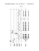
[0053] Meanwhile, the embodiment of the present invention illustrated in FIG. 1 uses a sinusoidal-shaped readout gradient but is not necessarily limited thereto, and therefore for example, a trapezoidal readout gradient may also be used.
[0054] FIG. 6 illustrates a pulse sequence according to the embodiment of the present invention using the trapezoidal reading gradient. As illustrated in FIG. 6, the remaining portions of the pulse sequence are the same as those illustrated in FIG. 1, but instead of the sinusoidal-shaped reading gradient, a trapezoidal frequency selection readout gradient may be used.
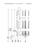
[0055] Further, to improve the T2* result value, a navigation echo may also be used.
[0056] FIGS. 7 and 8 each illustrate the pulse sequence according to the embodiment of the present invention additionally using three navigator echoes in the pulse sequences illustrated in FIGS. 1 and 6.
[0057] As described above, the T2* values fitted based on a sufficient amount of acquired
[0058] TE images as in the embodiment of the present invention provide much more accurate values than values provided by an underestimated or overestimated fitting only based on 12 images according to the existing method.
[0059] Further, the method for acquiring an MRI image in accordance with the embodiment of the present invention may rapidly and accurately acquire data without the nerve impulse or acoustic noise and the flipped fitting method may more appropriately and accurately calculate the T2* value.
[0060] While the present invention has been shown and described in connection with the exemplary embodiments, it will be apparent to those skilled in the art that modifications and variations can be made without departing from the spirit and scope of the invention as defined by the appended claims.
User Contributions:
Comment about this patent or add new information about this topic:
Images included with this patent application:
 |  |
 |  |
 |  |
 |
| New patent applications in this class: | |
| Date | Title |
|---|---|
| 2022-05-05 | Magnetic resonance (mr)-scanner control |
| 2019-05-16 | Voxelwise spectral profile modeling for use in multispectral magnetic resonance imaging |
| 2019-05-16 | Signal-preserving noise decorrelation |
| 2019-05-16 | Method for improving signal-to-noise ratio in magnetic resonance imaging |
| 2019-05-16 | Systems and methods for ultrashort echo time magnetization transfer (ute-mt) imaging and signal modeling |
| New patent applications from these inventors: | |
| Date | Title |
|---|---|
| 2019-09-12 | Variable pet apparatus |
| 2017-05-18 | Method for acquiring t2* and vascular images from magnetic resonance imaging system |
| 2015-12-31 | Method of measuring blood flow velocity performed by medical imaging apparatus, and the medical imaging apparatus |
| 2015-08-27 | Motion vector smoothing method and apparatus |
| 2015-04-30 | Image processing method and medical imaging apparatus employing the method |
| Top Inventors for class "Electricity: measuring and testing" | |
| Rank | Inventor's name |
|---|---|
| 1 | Udo Ausserlechner |
| 2 | David Grodzki |
| 3 | Stephan Biber |
| 4 | William P. Taylor |
| 5 | Markus Vester |