Patent application title: Elastic Cord for a Pull Exerciser
Inventors:
Yung-Cheng Wu (Tainan, TW)
IPC8 Class: AA63B21055FI
USPC Class:
482126
Class name: Utilizing resilient force resistance and user supplied counter force having pair of handles
Publication date: 2016-01-28
Patent application number: 20160023036
Abstract:
An elastic cord includes a hollow outer elastic cord having a first end
and a second end spaced from the first end in a longitudinal direction.
The hollow outer elastic cord further includes a hole extending from the
first end thereof through the second end thereof. The hollow outer
elastic cord further includes an outer periphery and an inner periphery
spaced from the outer periphery in a radial direction perpendicular to
the longitudinal direction. A rib is provided in the hole of the hollow
outer elastic cord and extends from the first end through the second end
of the hollow outer elastic rod. The rib includes a first portion
connected to the inner periphery of the hollow outer elastic cord and a
second portion connected to the inner periphery of the hollow outer
elastic cord.Claims:
1. An elastic cord comprising a hollow outer elastic cord including a
first end and a second end spaced from the first end in a longitudinal
direction, with the hollow outer elastic cord further including a hole
extending from the first end thereof through the second end thereof, with
the hollow outer elastic cord further including an outer periphery and an
inner periphery spaced from the outer periphery in a radial direction
perpendicular to the longitudinal direction, with a rib provided in the
hole of the hollow outer elastic cord and extending from the first end
through the second end of the hollow outer elastic rod, and with the rib
including a first portion connected to the inner periphery of the hollow
outer elastic cord and a second portion connected to the inner periphery
of the hollow outer elastic cord.
2. The elastic cord as claimed in claim 1, wherein the rib further includes a third portion connected to the inner periphery of the hollow outer elastic cord.
3. The elastic cord as claimed in claim 2, wherein the rib has substantially Y-shaped cross sections perpendicular to the longitudinal direction.
4. The elastic cord as claimed in claim 2, wherein the rib further includes a fourth portion connected to the inner periphery of the hollow outer elastic cord.
5. The elastic cord as claimed in claim 4, wherein the rib has substantially cruciform cross sections perpendicular to the longitudinal direction.
Description:
BACKGROUND OF THE INVENTION
[0001] The present invention relates to an elastic cord for a pull exerciser and, more particularly, to an elastic cord including a rib to avoid injury to a user when the elastic cord breaks during use.
[0002] Pull exercisers utilizing elastic cords allow exercise of muscles of the breast and arms of a user. These pull exercisers are light, small, and easy to carry and are, thus, a preferred option to modern people.
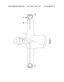
[0003] A typical elastic cord of a pull exerciser is hollow and attached between two handles. An exercise effect in the muscles of the breast and arms of a user can be attained when the user holding the handles repeatedly stretches and releases the elastic cords. However, with reference to FIG. 1, when a user 1 holds the handles 101 of a conventional pull exerciser 10 and stretches the elastic cord 102, the elastic cord 102 could break and injure the user 1.
[0004] Thus, a need exists for an improved elastic cord for an exerciser that would not injure the user when it breaks during use.
BRIEF SUMMARY OF THE INVENTION
[0005] An elastic cord according to the present invention includes a hollow outer elastic cord having a first end and a second end spaced from the first end in a longitudinal direction. The hollow outer elastic cord further includes a hole extending from the first end thereof through the second end thereof. The hollow outer elastic cord further includes an outer periphery and an inner periphery spaced from the outer periphery in a radial direction perpendicular to the longitudinal direction. A rib is provided in the hole of the hollow outer elastic cord and extends from the first end through the second end of the hollow outer elastic rod. The rib includes a first portion connected to the inner periphery of the hollow outer elastic cord and a second portion connected to the inner periphery of the hollow outer elastic cord.
[0006] In an example, the rib further includes a third portion connected to the inner periphery of the hollow outer elastic cord. The rib has substantially Y-shaped cross sections perpendicular to the longitudinal direction.
[0007] In another example, the rib further includes a fourth portion connected to the inner periphery of the hollow outer elastic cord. The rib has substantially cruciform cross sections perpendicular to the longitudinal direction.
[0008] The present invention will become clearer in light of the following detailed description of illustrative embodiments of this invention described in connection with the drawings.
DESCRIPTION OF THE DRAWINGS
[0009] The illustrative embodiments may best be described by reference to the accompanying drawings where:
[0010] FIG. 1 is a schematic view of a user and a conventional pull exerciser with an elastic cord of the pull exerciser broken during use.
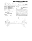
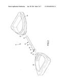
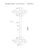
[0011] FIG. 2 is an exploded, perspective view of a pull exerciser utilizing an elastic cord of a first embodiment according to the present invention.
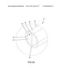
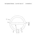
[0012] FIG. 2A is an enlarged view of a circled portion of FIG. 2.
[0013] FIG. 3 is a side view of the elastic cord of FIG. 2.
[0014] FIG. 4 is a partial, perspective view of the pull exerciser utilizing the elastic cord of FIG. 2.
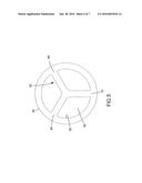
[0015] FIG. 5 is a side view of an elastic cord of a second embodiment according to the present invention.
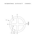
[0016] FIG. 6 is a side view of an elastic cord of a third embodiment according to the present invention.
[0017] All figures are drawn for ease of explanation of the basic teachings only; the extensions of the figures with respect to number, position, relationship, and dimensions of the parts to form the illustrative embodiments will be explained or will be within the skill of the art after the following teachings have been read and understood. Further, the exact dimensions and dimensional proportions to conform to specific force, weight, strength, and similar requirements will likewise be within the skill of the art after the following teachings have been read and understood.
[0018] Where used in the various figures of the drawings, the same numerals designate the same or similar parts. Furthermore, when the terms "first", "second", "third", "fourth", "end", "portion", "outer", "longitudinal", "radial", "length", and similar terms are used herein, it should be understood that these terms have reference only to the structure shown in the drawings as it would appear to a person viewing the drawings and are utilized only to facilitate describing the illustrative embodiments.
DETAILED DESCRIPTION OF THE INVENTION
[0019] An elastic cord of a first embodiment according to the present invention is shown in FIGS. 2-4 of the drawings and generally designated 16. In an example shown in FIG. 2, the elastic cord 16 is utilized with a pull exerciser 12 of the type including two handles 38. Each end of the elastic cord 16 is knotted after extending through a through-hole 40 of one of the handles 38 to prevent the elastic cord 16 from disengaging from the through-hole 40.
[0020] With reference to FIGS. 2-4, the elastic cord 16 of the first embodiment includes a hollow outer elastic cord 50 that is elongated and that can be formed by extruding thermoplastic rubber (TPR). The hollow outer elastic cord 50 can be repeatedly stretched with a force and can restore its original length after the force is released. The hollow outer elastic cord 50 includes a first end 52 and a second end 54 spaced from the first end 52 in a longitudinal direction. The hollow outer elastic cord 50 includes a hole 60 extending from the first end 52 through the second end 54. The hollow outer elastic cord 50 further includes an outer periphery 56 and an inner periphery 58 spaced from the outer periphery 56 in a radial direction perpendicular to the longitudinal direction. The inner periphery 58 defines the hole 60. A rib 62 is formed in the hole 60 and includes a first portion 64 connected to the inner periphery 58 and a second portion 66 connected to the inner periphery 58. The first portion 64 and the second portion 66 are spaced from each other in a radial direction perpendicular to the longitudinal direction and form a rectilinear shape (FIGS. 2A and 3). In this embodiment, the rib 62 extends from the first end 52 through the second end 54 of the hollow outer elastic rod 50.
[0021] The rib 62 increases the structural strength of the elastic cord 16. When the outer periphery 56 or the inner periphery 58 of the elastic cord 16 is damaged and if the hollow outer elastic cord 50 begins to break from the damaged portion, the rib 62 resists the crack from running through the rib 62 to prevent complete breakage of the elastic cord 16. Thus, the user has a higher chance to find observe the damage of the elastic cord 16 before the elastic cord completely breaks, reducing the risks of injury to the user by the elastic cord 16 in an unexpected situation.
[0022] FIG. 5 shows an elastic cord 16 of a second embodiment modified from the first embodiment. In this embodiment, the rib 62 includes first, second and third portions 64, 66, and 70. All of the first, second, and third portions 64, 66, and 70 are connected to the inner periphery 58 of the hollow outer elastic cord 50. The first, second, and third portions 64, 66, and 70 are spaced from each other by 120°. Thus, the rib 62 has substantially Y-shaped cross sections perpendicular to the longitudinal direction.
[0023] FIG. 6 shows an elastic cord 16 of a third embodiment modified from the first embodiment. In this embodiment, the rib 62 includes first, second, third, and fourth portions 64, 66, 70, and 72. All of the first, second, third, and fourth portions 64, 66, 70, and 72 are connected to the inner periphery 58 of the hollow outer elastic cord 50. The first, second, third, and fourth portions 64, 66, 70, and 72 are spaced from each other by 90°. Thus, the rib 62 has substantially cruciform cross sections perpendicular to the longitudinal direction.
[0024] The second and third embodiments of the elastic cord 16 also provide the same effect of increasing the structural strength of the elastic cord 16. Thus, when the outer periphery 56 or the inner periphery 58 of the elastic cord 16 is damaged, the rib 62 can delay complete breakage of the elastic cord 16 for a period of time. Thus, the user has a higher chance to observe the damage to the elastic cord 16 before the elastic cord completely breaks.
[0025] Now that the basic teachings have been explained, many extensions and variations will be obvious to one having ordinary skill in the art. For example, the elastic cord 16 can be made of thermoplastic rubber or other elastic materials. Furthermore, the rib 62 having three portions 64, 66, and 70 can have solid triangular cross sections perpendicular to the longitudinal direction or hollow triangular cross sections perpendicular to the longitudinal direction. The rib 62 having four portions 64, 66, 70, and 72 can have solid rectangular cross sections perpendicular to the longitudinal direction or hollow rectangular cross sections perpendicular to the longitudinal direction. Thus, the structural strength of the elastic cord 16 can be increased if a plurality of portions of the rib 62 is connected to the inner periphery 58 of the hollow outer elastic cord 50. The shape of the cross sections of the rib 62 is not limited.
[0026] Thus since the illustrative embodiments disclosed herein may be embodied in other specific forms without departing from the spirit or general characteristics thereof, some of which forms have been indicated, the embodiments described herein are to be considered in all respects illustrative and not restrictive. The scope is to be indicated by the appended claims, rather than by the foregoing description, and all changes which come within the meaning and range of equivalency of the claims are intended to be embraced therein.
User Contributions:
Comment about this patent or add new information about this topic:
Images included with this patent application:
 |  |
 |  |
 |  |
 |  |
| Similar patent applications: | |
| Date | Title |
|---|---|
| 2016-01-14 | Methods and devices for sensing, guiding, and/or tracking pelvic exercise |
| 2015-12-31 | Resistance motor for exercise apparatus |
| 2016-01-28 | Resistance adjustment device for exerciser |
| 2016-02-04 | Apparatus and method directed to an exercise and stretching therapy bar |
| 2015-10-29 | Flexible handle for a dumbbell weight |
| New patent applications in this class: | |
| Date | Title |
|---|---|
| 2016-07-14 | Safety device for exercise resistance band |
| 2016-07-07 | Resistance training apparatus |
| 2016-07-07 | Interchangeable resistance tube assembly |
| 2016-05-12 | Exercise apparatus, methods of using, and method of manufacture |
| 2016-03-10 | Exercise device and buckle |
| Top Inventors for class "Exercise devices" | |
| Rank | Inventor's name |
|---|---|
| 1 | William T. Dalebout |
| 2 | Scott R. Watterson |
| 3 | Raymond Giannelli |
| 4 | Leao Wang |
| 5 | Bruce Hockridge |