Patent application title: EARTHQUAKE PROOF BUILDING SYSTEM
Inventors:
Cemalettin Kaya (Istanbul, TR)
IPC8 Class: AE02D2734FI
USPC Class:
521674
Class name: Static structures (e.g., buildings) means compensating earth-transmitted force (e.g., earthquake) relative motion means between a structure and its foundation
Publication date: 2016-01-21
Patent application number: 20160017565
Abstract:
A building system that eliminates earthquake's destructive effect
includes the 1st Foundation enables the building to hold on the ground,
the 2nd-Foundation moves on the 1st-Foundation, the foundation
cantilever of the 2nd-Foundation, the impact cantilever as the
structural element surrounding the 1st-Foundation, external curtain
meets ground actions forming structural cavity, earthquake wedge dampens
portion of the impact of the foundation cantilever to the impact
cantilever, movement mechanism enables articulated movement between 1st
and 2nd-Foundations, support panel is the structural element
enabling ground actions to safely support the external curtain and
increases strength of the impact cantilever, reinforced concrete cap
prevents foreign materials from entering the structure's travel cavity
and tension piles prevents the tipping over of the structure connected to
the 1st Foundation.Claims:
1. This invention relates to building systems developed against
earthquake, comprises: the 1st Foundation, forming the
rigid--fixed--section of the building sunken in the ground, the 2nd
Foundation on the 1st Foundation, the distance between them determined by
calculation, which can move independently on the 1st Foundation and
supports the building floors on itself, the foundation cantilever located
around the 2nd Foundation which enables the consuming of earthquake
internal forces with the horizontal and/or vertical loads being
transferred by its impact on the impact cantilever, the impact cantilever
at the end section of the 1st Foundation and surrounding it, which houses
the foundation cantilever in the 2nd Foundation inside it at a certain
distance and to which the foundation cantilever impacts during an
earthquake with the action of the earthquake forces and ensured the
consuming of earthquake internal forces, and the movement mechanism which
moves together with the ground during an earthquake and which enables the
2nd Foundation to move independently and in all directions over the 1st
Foundation.
2. The non-earthquake building system mentioned in claim 1 comprises the earthquake wedge on the inner surface of the impact cantilever which dampens a portion of the impact forces formed during the impact of the foundation cantilever to the impact cantilever.
3. The non-earthquake building system mentioned in claim 1 comprises the tension pile connected to the 1st Foundation, which advances towards the ground at an angle and due to its angular placement forms additional tension force by virtue of the shear force of the ground.
4. The non-earthquake building system mentioned in claim 1 comprises the tension pile connected to the 1st Foundation, which advances towards the ground at an angle and enables the increasing of the soil safety of the building against ground settling by the compressive force formed with the building's own weight when there is no earthquake.
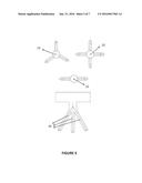
5. The tension pile mentioned in claim 3, wherein the number of angular arms of the tension pile is at least two and the arm angles are produced at an angle to the vertical axis.
6. The non-earthquake building system mentioned in claim 1 comprises the external curtain which meets the ground loads around the structure travel cavity and forms the structure's travel cavity and increases the strength of the impact cantilever during the impact of the foundation cantilever on the impact cantilever during an earthquake.
7. The non-earthquake building system mentioned in claim 1 comprises the support panel which increases the safety of the external curtain located around the structure travel cavity and on the impact cantilever against ground loads, which increases the strength of the impact cantilever during the impact of the foundation cantilever to the impact cantilever.
8. The non-earthquake building system mentioned in claim 1 comprises the reinforced concrete cap which covers the structure's travel cavity and protects from foreign material.
Description:
[0001] This invention relates to non-earthquake building system which can
be applied on all kinds of separate regime buildings, which eliminates
the destructive effect of the earthquake, the loss of lives and property
in medium and severe intensity earthquakes, by damping earthquake forces
acting on the building inside two foundation structures which move
independently of each other without transferring the earthquake forces
from the building's foundation to upper floors.
[0002] Earthquake is known as a natural disaster the effects and time of which cannot be precisely determined. The fact that the effects and time of the earthquake cannot be determined precisely causes the measures required to be taken for the future remain limited.
[0003] Measures which can be taken against earthquake comprise alterations made on the building structure and statics to enable the building to maintain its integrity during an earthquake, and shelters, automatic gas-power cut off systems to prevent incidents like fire, collapse and explosions during the earthquake.
[0004] In the building project, prepared before the building is constructed, building static calculations are made for estimated earthquakes. The building is constructed according to the static calculations made. However, precise analysis relating to the behavior of the building during the earthquake cannot be performed from estimated conditions and earthquake intensities. Statics calculations are made for two directions and no calculation method exists for earthquakes which come transversally or from the bottom. Therefore, the durability of the building can be maintained within the statics calculations made and the conditions specified. In unexpected situations, the wear brought about by the passing of long years and earthquakes which cannot be estimated prevent having information related to the time-endurance of the building. In this manner the building becomes more dangerous.
[0005] There exist various systems which are placed during the construction of buildings for the buildings to remain erect during an earthquake. Systems such as rail systems, rubber skidders, energy absorption springs, pre-tensioned cables absorb the earthquake forces created by the earthquake. However, these systems cannot be implemented on all kinds of buildings. Additionally these systems, despite providing protection against earthquake, their costs are considerably high.
[0006] This invention, which can be applied on all kinds of separate regime buildings, which relates to a non-earthquake building system that eliminates the destructive effect of the earthquake and prevents loss of lives and property in medium or severe intensity earthquakes by damping the earthquake forces within two foundation structures moving independently of each other in impact cantilevers before the earthquake forces acting on the building are transferred from the foundation of the building to the upper floors, entirely overcomes the above described disadvantages and is characterized in that; it comprises a new foundation embodiment which prevents the transfer of earthquake forces to the upper floors of the building, by dampening them by virtue of the foundations located on the building's foundation and which are located on top of each other, and movement mechanisms and impact cantilevers located in between the said foundations, no matter by which angle earthquake forces come on the horizontal and/or vertical plane, and prevents the building from tipping over due to centrifugal force by virtue of the rigid area of the structure.
[0007] It can be applied in separate regime structures of all types regardless of their geometric structure, the number of floors, with or without basements, with the area of the basement or floors larger than the building's main mass and entirely surrounding the main structure.
[0008] There are two foundations in the building which are independent of each other. The first foundation is among the most important structural elements of the rigid structure body which sits on the natural ground, which has impact cantilevers, external curtains, reinforced concrete support panels surrounding it, and anchored to the ground by tension piles. Structural loads are transferred to the ground by this foundation. The structure's own weights transferred to the second foundation are transferred to the first foundation by the movement mechanical located in between the two foundations. The second foundation, on the other hand, is the foundation which is located under the moving structure, which sits on the first foundation with it movement mechanism, which has foundation cantilevers around it. The structure's moving body is constructed on the second foundation. No matter which direction earthquake forces come from they can move opposite the direction of the earthquake in all directions without an angle on the movement mechanism located in the second foundation under each column. This system which is fully articulated does in no way transfer neither the earthquake moments nor the shear forces to the superstructure. Around the 1st foundation, on the other hand, which is anchored to the ground via tension piles, there are impact cantilevers and on the top end sections of the impact cantilevers there are external curtains. The reinforced concrete cap is the steel element which is connected to the moving structure and protects the building travel cavity from foreign materials.
[0009] There are two foundation embodiments in the building's foundation which can move independently of each other. When earthquake forces come from different directions the two foundations moving independently of each other prevent the earthquake forces to reach the upper floors.
[0010] In the building's foundation, while the two foundations are moving independently of each other the earthquake forces are transformed into impact forces by virtue of the impact cantilevers. After the earthquake forces are transformed into impact forces, while the wedges bear a portion of the impact force, at the same time, when the foundation cantilever impacts on the impact cantilever it dampens a portion of the impact force. At the same time it softens the impact of the foundation cantilever and the impact cantilever.
[0011] In the event of an earthquake the tension piles prevent the tipping over of the building under the earthquake effect. Tension piles operate on pressure force when there is no earthquake and on tensile force during earthquake. The dampening of earthquake forces in the building's foundation prevents destructive effect of earthquake forces from reaching the upper floors and eliminates loss of lives and property. The non-earthquake building system which eliminated earthquake risk offers a permanent measure against earthquake.
[0012] This invention is described in the foregoing by only exemplifying in more detail with reference to the drawings in the attachment, in those drawings;
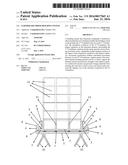
[0013] FIG. 1 Is the general view of the non-earthquake building system.
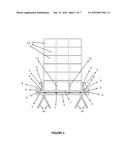
[0014] FIG. 2 Is the general view of the behaviors seen in the earthquake wave in the non-earthquake building system from left to right.
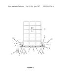
[0015] FIG. 3 Is the general view of the behaviors seen in the earthquake wave in the non-earthquake building system from right to left.
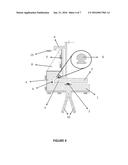
[0016] FIG. 4 Is the view of corner detail in the non-earthquake building system.
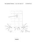
[0017] FIG. 5 Is the general view of the tension pile with and embodiment of different number of arms.
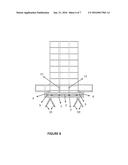
[0018] FIG. 6 Is the general view of basement floor and floors area being larger than the building area, the basement or floors being rigid in the non-earthquake building system.
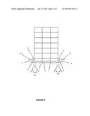
[0019] FIG. 7 Is the general view without basement in the non-earthquake building system.
TABLE-US-00001
[0020] Description of references: NO PART NAME 1 1st foundation 2 2nd foundation 3 Foundation cantilever 4 Impact cantilever 5 External curtain 6 Earthquake wedge 7 Movement mechanism 8 Support panels 9 Reinforced concrete cap 10 Tension pile 11 Structural column 12 Building floors 13 Ground level 14 Earthquake direction 15 Building's movement direction
[0021] This invention, which relates to a non-earthquake building system which can be applied on all kinds of separate regime buildings, which eliminates the destructive effect of the earthquake, the loss of lives and property in medium and severe intensity earthquakes, by damping earthquake forces acting on the building inside two foundation structures which move independently of each other without transferring the earthquake forces from the building's foundation to upper floors, comprises in general, 1st Foundation (1) the fixed foundation which anchors the building to the ground, the 2nd Foundation (2) moving on the 1st Foundation (1), the foundation cantilever (3) of the 2nd Foundation (2), the impact cantilever (5) as the steel element surrounding the 1st Foundation (1), the external curtain (6) which is the bears ground actions and forms a structural cavity, the earthquake wedge (6) which dampens a portion of the impact energy during the impact of the foundation cantilever (3) to the impact cantilever (4), the movement mechanism (7) which provides the articulated move between the 1st Foundation (1) and the 2nd Foundation (2), the support panel (8) which is the structural element which enables ground actions to be safely carried by the external curtain (5) and increases the strength of the impact cantilever (4), the reinforced concrete cap (9) which prevents foreign material from entering the structure travel cavity, and the tension piles (10) which are the structural elements that prevent the structure connected to the 1st Foundation (1) from tipping over.
[0022] The utilization of the invention is as follows:
[0023] The 1st Foundation (1) is the structural element of the rigid area of the building which is sunken in the ground. The 1st Foundation (1) is implemented in the state of the art in the form of laying a foundation at a certain depth of the ground with foundation laying methods.
[0024] The 2nd Foundation (2) is a foundation structure, which can move independently on the 1st Foundation (1) and carries the building floors (2) on itself. The 2nd Foundation (2) is located at a certain distance above the 1st Foundation (1). The 1st Foundation (1) together with the 2nd Foundation (2) support the whole structure. The structure rises on the 2nd Foundation (2) with the building floors (2). On the 2nd Foundation (2) structural columns (1) are erected.
[0025] The foundation cantilever (3) is the structural element surrounding the 2nd Foundation (2). It continues in the same dimensions and thickness throughout the circumference of the 2nd Foundation (2). It enables the internal forces of the earthquake to be consumed.
[0026] The impact cantilever (4) is the structural element at the tip of the 1st Foundation (1) which goes around the 1st Foundation (1). The impact cantilever (4) surrounds the foundation cantilever (3) located in the 2nd Foundation (2). During an earthquake the foundation cantilever (3) impacts on the impact cantilever (4). With this impact the earthquake internal forces are consumed.
[0027] The external curtain (5) is the structural element at the tip of the impact cantilever (4) forming the structural cavity which bears the ground actions on the impact cantilever (4). It increases the strength of the impact cantilever (4) in the event the building tips over during an earthquake.
[0028] The earthquake wedge (6), on the inner surface of the impact cantilever (4), dampens a portion of the impact forces formed during the impact of the foundation cantilever (3) to the impact cantilever (4) and at the same time softens the impact of the foundation cantilever (3) and the impact cantilever (4).
[0029] The movement mechanism (7) is the mechanism which provides support and movement between the 1st Foundation (1) and the 2nd Foundation (2). The movement mechanism (7) enables the 2nd Foundation (2) to move independently and in all directions on the 1st Foundation (1) during an earthquake. At the same time it is the structural element which transfers the building's own weight to the 1st Foundation (1).
[0030] Support panels (8) are structural elements which increase the strength of the external curtain against ground loads around the external curtain (5) located on the top end portion of the impact cantilever (4) around the 1st Foundation (1). During the strike of the foundation cantilever (3) to the impact cantilever (4) the strength of the impact cantilever (4) increases. The top elevation of support panels (8) is at ground level (3).
[0031] The residential reinforced concrete cap (9) is the structural element which prevents foreign material entering the structure's travel cavity.
[0032] The tension pile (10) increases the hold of the 1st Foundation (1) in the ground and prevents the building tipping over during an earthquake. The tension pile (10) has foundation pile arms which are connected to the foundation and which advance at an angle towards the ground. The number of tension piles (10) vary according to the need, building height and soil structure. Due to the angular layout of the arms of the tension pile (10), it creates additional tension force in the ground by virtue of the shear resistance of the ground above itself. The tipping off of the building is prevented by virtue of the tension pile (10). The tension pile (10) is poured on the ground at an angle and within reinforcement before the 1st Foundation (1) is formed and on it the 1st Foundation (1) is seated. When no earthquake is present, the ground safety of the building against settling in the ground is increased with tension piles (10) with the compressive strength formed by the building's own weight.
[0033] In the non-earthquake building system, after the process of preparing the ground for foundation laying is completed; the tension piles (10) are made on the ground, with a determined number of arms and angles. After the completion of the tension piles (10) the 1st Foundation (1) is formed in connection with the tension piles (10). The impact cantilever (4), external curtain (5) and support panels (8) are made around the 1st Foundation (1). When the impact cantilever (4) is formed the earthquake wedge (6) is placed in the inner part of the impact cantilever (4).
[0034] On the 1st Foundation (1) the movement mechanism (7) is placed. On the level of the movement mechanism (7) in the form remaining above the 1st Foundation (1) is filled with filling material. The filling material, which does not prevent the horizontal movement of the building, acts at the same time as formwork for the 2nd Foundation (2). The 2nd Foundation (2) is formed on the filling material. When the 2nd Foundation (2) is being formed, the foundation cantilever (3) which surrounds the 2nd Foundation (2) is formed together with the 2nd Foundation (2). The building floors (13) are continued on the 2nd Foundation (2). After the filling material is placed in the internal surface of the impact cantilever (4) and the internal surface of the external curtain (5) the installation of the reinforcement is made. Afterwards the concrete laying and impact cantilever (4) and the structure travel cavity are formed. The filling material forms the internal formwork of the impact cantilever (4) and the external formwork of the foundation cantilever (3) produced in the second stage and serves the function of cavity. With the filling material placed in between the impact cantilever (4) and the forces the structure's travel cavity is formed.
[0035] The behavior of the non-earthquake building during an earthquake in the event the earthquake waves come in the horizontal or vertical planes;
[0036] In the event earthquake waves come in the horizontal plane from right to left; the 1st Foundation (1) moves in the earthquake direction (14) together with the ground. With the movements of the earthquake waves, the 2nd Foundation (2) moves on the 1st Foundation (1) in a direction opposite to the earthquake direction (14). Together with the 2nd Foundation (2) the building moves opposite to the earthquake direction (4) in the building's movement direction (15). During this movement in the first movement the right foundation cantilever (3) impacts on the impact cantilever (4) on the right hand side. When the foundation cantilever (3) impacts on the impact cantilever (4), earthquake forces are converted to impact forces and a portion of them are dampened by the impact cantilever (4). The earthquake wedge (6), which is located in the inner part of the impact cantilever (4) dampens a portion of the impact forces during the impact of the foundation cantilever (3) to the impact cantilever (4) and softens the impact. During the time the force caused by earthquake waves is trying to tip the building over, the foundation cantilever (3) located on the left hand side makes an upward movement and strikes the bottom surface of the impact cantilever (4) on the left hand side. The impact cantilever (4) also dampens the impact force formed in the vertical direction. In the bottom section of the inner surface of the impact cantilever (4) there is also an earthquake wedge (6) and dampens a portion of the impact force. The tipping force is transferred to the tension pile (10) and the tipping of the building is prevented.
[0037] In the event earthquake waves come in the horizontal plane from left to right; the 1st Foundation (1) moves in the earthquake direction (14) together with the ground. With the movements of the earthquake waves, the 2nd Foundation (2) moves on the 1st
[0038] Foundation (1) in a direction opposite to the earthquake direction (14). Together with the 2nd Foundation (2) the building moves opposite to the earthquake direction (14) in the building's movement direction (15). During this movement in the first movement the left foundation cantilever (3) impacts on the impact cantilever (4) on the left hand side. When the foundation cantilever (3) impacts on the impact cantilever (4), earthquake forces are converted to impact forces and a portion of them are dampened by the impact cantilever (4). The earthquake wedge (6), which is located in the inner part of the impact cantilever (4) dampens a portion of the impact forces during the impact of the foundation cantilever (3) to the impact cantilever (4) and softens the impact. During the time the force caused by earthquake waves is trying to tip the building over, the foundation cantilever (3) located on the right hand side makes an upward movement and strikes the bottom surface of the impact cantilever (4) on the right hand side. The impact cantilever (4) also dampens the impact force formed in the vertical direction. In the bottom section of the inner surface of the impact cantilever (4) there is also an earthquake wedge (6) and dampens a portion of the impact force. The tipping force is transferred to the tension pile (10) and the tipping of the building is prevented.
[0039] In the event earthquake waves come in the vertical plane from the bottom up; because all foundation cantilevers (3) and impact cantilevers (4) operate in the vertical direction simultaneously, the destructive forces of the earthquake are met in a safer manner.
[0040] Earthquake waves coming in the mentioned directions and planes may come by acting both on the horizontal and the vertical plane in a manner acting on more than one planes. In that event it is possible for the system behavior to operate simultaneously during the ne moment of earthquake. By virtue of this when an earthquake wave which acts in more than one plane--for example, an earthquake wave which has effect in both the vertical and the horizontal planes--is encountered, the mentioned behaviors can operate simultaneously.
User Contributions:
Comment about this patent or add new information about this topic:
Images included with this patent application:
 |  |
 |  |
 |  |
 |  |
| Similar patent applications: | |
| Date | Title |
|---|---|
| 2016-05-12 | Load bearing interlocking structural blocks and modular building system |
| 2016-03-24 | Interlocking building system |
| 2016-04-21 | Tile roof mounting systems |
| 2016-05-05 | Modular roof panel with integrated drainage system |
| 2016-05-12 | An insulating roof support assembly, a method of installing such roof support assembly and an insulating roof construction |
| New patent applications in this class: | |
| Date | Title |
|---|---|
| 2016-05-12 | Seismic isolation assembly |
| 2015-11-05 | Seismic isolation system |
| 2015-10-29 | Methods and apparatus of building construction resisting earthquake and flood damage |
| 2015-10-22 | Systems and methods for providing base isolation against seismic activity |
| 2014-10-30 | Class of bearings to protect structures from earthquake and other similar hazards |
| Top Inventors for class "Static structures (e.g., buildings)" | |
| Rank | Inventor's name |
|---|---|
| 1 | Darko Pervan |
| 2 | Gregory F. Jacobs |
| 3 | Husnu M. Kalkanoglu |
| 4 | Ronald P. Hohmann, Jr. |
| 5 | Mark Cappelle |