Patent application title: HEADER RETAINING SYSTEM FOR A LATERAL TRANSPORT CENTER PIVOT AGRICULTURAL MACHINE
Inventors:
IPC8 Class: AA01D7500FI
USPC Class:
56228
Class name: Harvesters transporting attachments
Publication date: 2016-01-14
Patent application number: 20160007534
Abstract:
A transport arrangement for an agricultural machine having a suspension
system. The transport arrangement includes a header unit a tongue
arrangement and a retaining system. The header unit is carried by the
suspension system. The tongue arrangement is coupled to the suspension
system, and is pivotal about an axis relative to the header unit and the
suspension system. The retaining system is configured to releasably
couple the tongue arrangement to the header unit and/or the suspension
system to thereby retain the header unit in an elevated position.Claims:
1. A transport arrangement for an agricultural machine having a
suspension system, the transport arrangement comprising: a header unit
carried by the suspension system; a tongue arrangement coupled to the
suspension system, said tongue arrangement being pivotal about an axis
relative to said header unit and the suspension system; and a retaining
system configured to releasably couple said tongue arrangement to at
least one of said header unit and the suspension system to thereby retain
said header unit in an elevated position.
2. The transport arrangement of claim 1, wherein said retaining system couples said tongue arrangement to one of said header unit and the suspension system as said tongue arrangement transitions from a field mode to a transport mode.
3. The transport arrangement of claim 2, wherein said retaining system is configured to uncouple said tongue arrangement from at least one of said header unit and the suspension system as said tongue arrangement transitions from a transport mode to a field mode.
4. The transport arrangement of claim 3, wherein said retaining system includes a hook and a receiving pin, said hook being captivated to said tongue arrangement, said receiving pin being coupled to one of said header unit and the suspension.
5. The transport arrangement of claim 4, wherein said receiving pin is coupled to said header unit.
6. The transport arrangement of claim 4, wherein said retaining system is configured to retain said header unit in an elevated position by said hook and said receiving pin without a use of hydraulic actuators while the transport arrangement is in the transport mode.
7. The transport arrangement of claim 4, wherein said hook is offset to a side of said tongue.
8. The transport arrangement of claim 7, wherein said hook has a U-shaped opening open in a generally horizontal direction.
9. The transport arrangement of claim 1, wherein said retaining system is further configured to releasably couple said tongue arrangement to at least one of said header unit and the suspension system in a passive manner.
10. The transport arrangement of claim 1, wherein the agricultural machine is an agricultural mower.
11. An agricultural mower, comprising: a chassis; a header unit carried by the chassis; a tongue arrangement coupled to said chassis, said tongue arrangement being pivotal about an axis relative to said header unit and said chassis; and a retaining system configured to releasably couple said tongue arrangement to at least one of said header unit and said chassis to thereby retain said header unit in an elevated position.
12. The agricultural mower of claim 11, wherein said retaining system couples said tongue arrangement to one of said header unit and said chassis as said tongue arrangement transitions from a field mode to a transport mode.
13. The agricultural mower of claim 12, wherein said retaining system is configured to uncouple said tongue arrangement from at least one of said header unit and the suspension system as said tongue arrangement transitions from a transport mode to a field mode.
14. The agricultural mower of claim 13, wherein said retaining system includes a hook and a receiving pin, said hook being captivated to said tongue arrangement, said receiving pin being coupled to one of said header unit and the chassis.
15. The agricultural mower of claim 14, wherein said receiving pin is coupled to said header unit.
16. The agricultural mower of claim 14, wherein said retaining system is configured to retain said header unit in an elevated position by said hook and said receiving pin without a use of hydraulic actuators while the agricultural mower is in the transport mode.
17. The agricultural mower of claim 14, wherein said hook is offset to a side of said tongue.
18. The agricultural mower of claim 17, wherein said hook has a U-shaped opening open in a generally horizontal direction.
19. The agricultural mower of claim 18, wherein said U-shaped opening diminishes in breadth towards a bottom of said U-shaped opening.
20. The agricultural mower of claim 11, wherein said retaining system is further configured to releasably couple said tongue arrangement to at least one of said header unit and the chassis in a passive manner.
Description:
BACKGROUND
[0001] 1. Field of the Invention
[0002] The subject disclosure relates to transport arrangements for agricultural machines, and, more particularly, relates to an arrangement for the machine, such as an agricultural mower, to enable the machine to be transitioned to a transport mode such that the header is retained in an elevated position.
[0003] 2. Description of the Related Art
[0004] Agricultural mowers and mower/conditioners, hereinafter referred to simply as mowers, are well known and include self-propelled and pull-behind types. A problem with pull-behind mowers involves the transporting of the machines between fields, since the width of the machine may exceed practical or regulatory limits. Machine movement may be necessary over farm lanes, through gates or on highways where the machine width will not allow passage in the operating orientation.
[0005] A typically solution is to place the mower-conditioner header mechanism on a separate trailer such that the lateral width of the mechanism is generally aligned with the length of the trailer (lateral transport) and then tow the trailer with the tractor. One such example is the Discbine® Transporter (by common assignee) which is specifically configured for loading, unloading, and laterally transporting a Model 1441/1442 disc mower conditioner while attached to the operating power unit (tractor). Such special trailers add significant cost, requires significant skill to load and unload, and must be used to transport the machine between locations or separately transported.
[0006] It would be advantageous to provide a reconfigurable transport arrangement for supporting a pull-behind mower header to be laterally transported while attached to a tractor and retaining the header of the mower in an elevated position without requiring an additional implement or special trailer. Further advantages would be realized by a lateral transport system that is quickly and easily transitioned to a passively retained header in an elevated position in the lateral transport configuration. Still further advantages would be realized by a lateral transport system that can be produced with less cost than the separate trailer lateral transport option it replaces.
SUMMARY
[0007] The following presents a simplified summary in order to provide a basic understanding of some aspects of the disclosed examples. This summary is not an extensive overview and is intended to neither identify key or critical elements nor delineate the scope of such aspects. Its purpose is to present some concepts in a simplified form as a prelude to the more detailed description that is presented later.
[0008] The subject disclosure provides a transport arrangement for supporting a mower allowing lateral transportation of the mower, with the header of the mower passively retained while attached to a tractor without requiring an additional implement or special trailer.
[0009] The disclosure in one form is directed to a transport arrangement for an agricultural machine having a suspension system. The transport arrangement includes a header unit a tongue arrangement and a retaining system. The header unit is carried by the suspension system. The tongue arrangement is coupled to the suspension system, and is pivotal about an axis relative to the header unit and the suspension system. The retaining system is configured to releasably couple the tongue arrangement to the header unit and/or the suspension system to thereby retain the header unit in an elevated position.
[0010] The disclosure in another form is directed to an agricultural mower including a chassis, a header unit carried by the chassis, a tongue arrangement and a retaining system. The tongue arrangement is coupled to the chassis. The tongue arrangement is pivotal about an axis relative to the header unit and the chassis. The retaining system is configured to releasably couple the tongue arrangement to the header unit and/or the chassis to thereby retain the header unit in an elevated position.
[0011] An advantage of the subject disclosure is that the lateral transport mode is accomplished without a separate implement or trailer.
[0012] Another advantage is that the transport mode is achieved using hydraulic controls available on the tractor and the header is passively retained in an elevated position.
[0013] To the accomplishment of the foregoing and related ends, one or more examples comprise the features hereinafter fully described and particularly pointed out in the claims. The following description and the annexed drawings set forth in detail certain illustrative aspects and are indicative of but a few of the various ways in which the principles of the various aspects may be employed. Other advantages and novel features will become apparent from the following detailed description when considered in conjunction with the drawings and the disclosed examples are intended to include all such aspects and their equivalents.
BRIEF DESCRIPTION OF THE DRAWINGS
[0014] The above-mentioned and other features and advantages of this disclosure, and the manner of attaining them, will become more apparent and the disclosure will be better understood by reference to the following description of an embodiment of the disclosure taken in conjunction with the accompanying drawings, wherein:
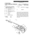
[0015] FIG. 1 is a perspective view of an agricultural machine in the form of a mower including a transport arrangement in the stowed position with part of the structure cut away to illustrate an embodiment of a retaining system of the present application;
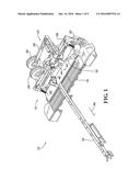
[0016] FIG. 2 is a top view of the mower with the retaining system shown in FIG. 1;
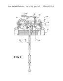
[0017] FIG. 3 is a perspective view of the mower shown in FIGS. 1 and 2, with the tongue shifted to a field use position;
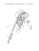
[0018] FIG. 4 is another perspective view of the mower of FIGS. 1-3, illustrating the transport arrangement of the present application being deployed;
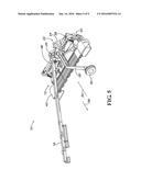
[0019] FIG. 5 is yet another perspective view of the mower of FIGS. 1-4, illustrating the transport arrangement of the present application being further deployed lifting the chassis of the mower;
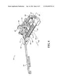
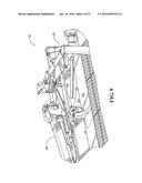
[0020] FIG. 6 is yet another perspective view of the mower of FIGS. 1-5, illustrating the tongue of the mower being pivoted to a transport position and the retaining system being engaged;
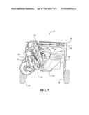
[0021] FIG. 7 is a front view of the mower of FIGS. 1-6, illustrating the transport arrangement of the present application being deployed for transporting the mower, from the perspective of the operator in a tractor;
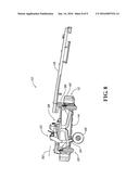
[0022] FIG. 8 is a side view of the mower of FIGS. 1-7, illustrating the transport arrangement of the present application being fully deployed having lifted the header of the mower and engaged the retaining system; and
[0023] FIG. 9 is a partial view of the transport arrangement of FIGS. 1-8 showing details of the retaining system.
[0024] Corresponding reference characters indicate corresponding parts throughout the several views. The exemplification set out herein illustrates an embodiment of the subject disclosure, and such exemplification is not to be construed as limiting the scope of the subject disclosure in any manner.
DETAILED DESCRIPTION
[0025] Referring now to the drawings, and more particularly to FIG. 1, there is shown a perspective view of an agricultural machine in the form of a mower 10, which can be attached to a tractor (not shown). Mower 10 generally includes a chassis 12, which carries a number of other components such as crop engaging blades 14, and drive components 16. A tongue 18 is pivotally connected to chassis 12, an end of which can be connected to the tractor. A field suspension system 20 supports mower 10 while mower 10 is in a field mode. Mower 10 additionally includes a transport arrangement 22, which, when deployed, provides the support for the transport of mower 10. Crop engaging blades 14 can be disc cutter blades 14 or a sickle bar, or another crop cutting device. Mower 10 additionally includes a retaining system 40 for the passive coupling of a header 42 to tongue 18. Retaining system 40 includes a hook 44 and a retaining pin 46.
[0026] Now, additionally referring to FIGS. 2-8, transport arrangement 22 includes suspension elements 24 and 26, which respectively have wheels 28 and 30 connected to corresponding ends of suspension elements 24 and 26. Suspension elements 24 and 26 are rotatable about an axis 32, when suspension element 26 is in the position shown in FIGS. 4-8. Additionally, suspension element 26 is rotatable about an axis 34 as it transitions from a stowed position illustrated in FIGS. 1-3 to the position shown in FIG. 4. Axis 32 is generally perpendicular to axis 34.
[0027] When suspension element 26 is in the stowed position it is generally above, or at least vertically elevated above, suspension element 24. Additionally, suspension element 26 is somewhat shorter than suspension element 24, as can be particularly seen in FIG. 2, where it can also be seen that suspension element 26 is positioned such that wheel 30 is behind wheel 28 when transport arrangement 22 is in a stowed position.
[0028] A sequence of movements of the elements of mower 10 will now be discussed with references to the various figures. FIGS. 1 and 2 illustrate transport arrangement 22 in a stowed position and tongue 18 is angularly positioned in a substantially forward direction 36. This is a configuration in which mower 10 can be used, but generally mower 10 will be used with tongue 18 located to either side, such as that shown in FIG. 3. FIG. 3 illustrates a predetermined position for tongue 18 to be located to allow the needed clearance for suspension element 26 to rotate about axis 34, as shown fully deployed, in FIG. 4. Initially the field wheels associated with field suspension system 20 are fully extended to lift chassis 12.
[0029] Once transport arrangement 22 is positioned as shown in FIG. 4, then both suspension elements 24 and 26 rotate about axis 32 causing wheels 28 and 30 to contact the ground thereby lifting chassis 12 so that field suspension system 20 is lifted off of the ground. Field suspension system 20 can be coordinated to also lift its wheels while or after wheels 28 and 30 contact the ground. The wheels of field suspension system 20 are raised to provide ground clearance by the retraction of the lift cylinders associated with field suspension system 20 (as can be seen in FIGS. 7 and 8). A result of this step is that transport arrangement 22 is fully deployed as seen in FIG. 5 and is in the transport position, except for the position of tongue 18. In FIGS. 1-5, retaining system 40 is not engaged and header 42 is completely under the control of actuators that position header 42 as suspension system 20 is deployed or retracted.
[0030] The next step is that tongue 18 is now swung to a transport position as shown in FIG. 6. This step has to wait on the full deployment of transport arrangement 22 to prevent mower 10 from tipping to one side. As tongue 18 is completely moved to the position shown in FIG. 6, hook 44 engages retaining pin 46 thereby securing header 42 in the raised position. With header 42 secured in a raised position if actuators that are used to raise header 42 are retracted, or simply slowly relax, retaining system 40 holds header 42 in the raised position as shown in FIGS. 6-9. FIGS. 7 and 8 show mower 10 in the transport mode respectively from the operator viewpoint and the right hand side of mower 10.
[0031] The steps needed to configure mower 10 for field use are the reverse of those just discussed in order to transition from the transport position to the stowed position of transport arrangement 22. The position of tongue 18 in the transport mode is at a small angle to the tracking of mower 10, as seen in FIG. 7, so as to position the hitch in the desired location for connection with the tractor.
[0032] Transport arrangement 22 is coupled to chassis 12 and more particularly to trail frame 38, which is part of chassis 12. The coupling of transport arrangement 22 is offset to the side of the centerline of mower 10. The folding mechanism of transport arrangement 22 is provided to allow at least portions of transport arrangement 22 to be stowed above and to the rear of the trail frame 38 during field operations. Upon placing the center pivot disc mower conditioner 10 (CPDMC) in the full field left position, the mechanism of transport arrangement 22 rotates about a pivot axis 34 that is parallel to or substantially parallel to the trail frame 38 (or the axis of the field wheels). This action can deploy the left hand (as in transport position) wheel to a position ahead of the header (ahead as in the field position) while still located above the trail frame 38. When this rotation has been completed, a secondary rotation takes place about axis 32; this action is a pivoting action, which is above, and perpendicular to the trail frame 38 and the field wheel axis. This action rotates wheels 28 and 30 from their position above trail frame 38 to a position below trail frame 38 and in contact with the ground.
[0033] When this action is complete, the trail frame/header is then rotated to a position essentially in-line with tongue 18, thus allowing a narrow transport for public roads. The steps to transition from field operation to lateral transport operation are thus: 1. Fully lift chassis 12 to the non-mowing position by extending the field wheels of field suspension system 20; 2. Rotate chassis 12 to the full field left position; 3. Extend the primary lateral transport cylinder to rotate suspension element 26 along with wheel 30 from a position above and behind the trail frame 38 to a position above and ahead of the trail frame 38; 4. Extend the secondary lateral transport cylinder to rotate suspension elements 24 and 26 with wheels 28 and 30 down below the trail frame 38, with wheel 28 being behind the header/trail frame 38 and wheel 30 being in front of the header/trail frame 38; 5. Initiate the system to complete the rotation of chassis 12 to the full lateral transport position and raise the field wheels. The steps to transition from lateral transport to field operation are then to reverse the actions starting with step 5 and work backward to step 1.
[0034] Header unit 42 is carried by suspension system 20. The tongue 18 arrangement is coupled to suspension system 20, with the tongue 18 arrangement being pivotal about an axis relative to header unit 42 and suspension system 20. The retaining system 40 is configured to releasably couple the tongue 18 arrangement to header unit 42 and/or suspension system 20 to thereby retain header unit 42 in an elevated position. As can be seen in FIG. 1, hook 44 has a U-shaped opening, which is positioned in an offset fashion relative to tongue 18, and the U-shaped opening is open in a generally horizontal direction. The U-shaped opening is configured to have a generally reduced throat toward the bottom of the U-shape, in order to capture, then retain, retaining pin 46.
[0035] The subject disclosure includes a tongue-mounted hook 44 extending down toward header 42. Hook 42 has a corresponding retaining pin 46 or shaft 46 mounted on the top of header 42. When header 42/trail frame 38 are rotated to the full lateral transport position, where header 42 and trail frame 38 are basically parallel to tongue 18, then hook 44, hanging down from tongue 18, and shaft 46 extending up from header 42 engage. When the field wheels are lifted to provide ground clearance, the engagement of hook 44 with shaft 46 does not allow header 42 to lower. However, the coupling of the heard lift arms to the wheel arms allows the field wheels to be lifted up. Any system can be used to actuate the lateral transport rotations, which engage and disengage hook 44 and shaft 46, with hydraulic cylinders being assumed, but the actions can be accomplished with any arrangement of cylinders, actuators, linear motors, rotational motors, to name a few.
[0036] Advantages of the subject disclosure include that retaining system 40 is completely position-based and passive. There are no pins or clasps that must be activated/actuated in order for the engagement to take place. Header 42 must only be lifted with the field wheels during the rotation, as the hydraulic system undertakes, in order for hook 44 to engage with shaft 46.
[0037] While this disclosure has been described with respect to at least one embodiment, the subject disclosure can be further modified within the spirit and scope of this disclosure. This application is therefore intended to cover any variations, uses, or adaptations of the disclosure using its general principles. Further, this application is intended to cover such departures from the subject disclosure as come within known or customary practice in the art to which this disclosure pertains and which fall within the limits of the appended claims.
User Contributions:
Comment about this patent or add new information about this topic:
Images included with this patent application:
 |  |
 |  |
 |  |
 |  |
 |  |
| Similar patent applications: | |
| Date | Title |
|---|---|
| 2016-04-21 | Sensor equipped agricultural harvester |
| 2016-05-05 | Adjustable roller frame assembly for pick-up reel |
| 2015-12-24 | Hybrid crop stripper band for a crop pick-up |
| 2016-01-21 | Bee broom apparatus for a power lawn mower |
| 2016-01-28 | System and method for baling agricultural crop material |
| New patent applications in this class: | |
| Date | Title |
|---|---|
| 2015-11-19 | Windrow merger |
| 2015-11-05 | Transport system for a header of an agricultural harvester |
| 2015-11-05 | Transport system for a center pivot agricultural machine |
| 2015-04-16 | Right side (front) lateral transport wheel linkage |
| 2012-06-07 | Agricultural header transport kit |
| Top Inventors for class "Harvesters" | |
| Rank | Inventor's name |
|---|---|
| 1 | Randy Lohrentz |
| 2 | Christopher T. Sauerwein |
| 3 | Benjamin M. Lovett |
| 4 | Neil Gordon Barnett |
| 5 | Martin E. Pruitt |