Patent application title: Cord Bracket and Method of Use
Inventors:
A. Shane Alcorn (Smithfield, UT, US)
IPC8 Class: AF16M1302FI
USPC Class:
248 741
Class name: Pipe or cable brackets with ring or clamp
Publication date: 2015-12-24
Patent application number: 20150369422
Abstract:
The present invention is a cord bracket use in temporarily securing
electrical cords and the like so as to prevent such electrical cords from
marring door casings or wall corners. The device preferably defines a
bracket having means for securing a cord and being adapted to
magnetically adhere to a door casing or wall corner. The bracket may
include a loop or a slot type holding means. Magnets of the bracket
preferably include a protective plastic layer to prevent the magnet from
causing damage to the door casing or wall corner.Claims:
1. A cord bracket apparatus apparatus having a body, a swivel base, and
at least one magnet, wherein said body includes at least one cord
retention member defining a loop and knob combination, and wherein said
body is connected to a first side of said swivel base and said magnet is
swivelably connected to a second side of said swivel base, and wherein
said apparatus is adapted such that when said apparatus is magnetically
mounted to a structure and a cord of an appliance is secured to said cord
retention member and said appliance is manipulated, said apparatus
prevents marring of said structure by said cord.
2. The apparatus of claim 1, wherein said securement of said cord to said cord retention member further defines said cord being threaded through said loop and over said knob.
3. The apparatus of claim 1, wherein said body defines at least one of a rigid body and a flexible body.
4. The apparatus of claim 2, wherein when an appliance manipulation induced pulling load is applied to said cord, said cord remains retained by said cord retention member.
5. The apparatus of claim 1, wherein said magnet includes a protective cover thereon adapted to prevent marring of said structure by said magnet.
6. The apparatus of claim 1, wherein in response to a pulling load applied to said cord secured to said apparatus, said apparatus swivels without releasing from said structure.
7. A cord bracket apparatus defining a body having at least one closed loop cord retention member and a mounting member adapted to temporarily mount said apparatus to a structure, wherein said apparatus is adapted such that when said apparatus is temporarily mounted to a structure and a cord of an appliance is passed through said closed loop cord retention member said cord is substantially free to move through said closed loop cord retention member and yet said cord is retained by said one closed loop cord retention member, and wherein when said appliance is manipulated, said apparatus prevents marring of said structure by said cord.
8. The apparatus of claim 7, wherein said closed loop cord retention member includes a knob, and wherein said cord is threaded through said closed loop cord retention member and around said knob.
9. The apparatus of claim 7, wherein said apparatus includes a swivel base.
10. The apparatus of claim 7, wherein said body defines at least one of a rigid body and a flexible body.
11. The apparatus of claim 7, wherein when an appliance manipulation induced pulling load is applied to said cord, said cord moves through said at least one closed loop cord retention member and vet said cord remains retained by said closed loop cord retention member.
12. The apparatus of claim 7, wherein said mounting member includes a protective cover thereon adapted to prevent marring of said structure by said magnet.
13. The apparatus of claim 7, wherein in response to a pulling load applied to said cord secured to said apparatus, said apparatus swivels without releasing from said structure.
14. A cord bracket apparatus defining a body having at least one cord retention member and a mounting member adapted to temporarily mount said apparatus to a structure, wherein said apparatus is adapted such that when said apparatus is temporarily mounted to a structure and a cord of an appliance is pressed into said cord retention member and said appliance is manipulated, said apparatus prevents marring of said structure by said cord.
15. The apparatus of claim 14, wherein said at least one cord retention member comprises a closed loop, and wherein when said cord is pressed into said closed loop and an appliance manipulation induced cord load is applied to said cord, said cord is retained by said closed loop.
16. The apparatus of claim 14, wherein said apparatus includes a swivel base.
17. The apparatus of claim 14, wherein said body defines at least one of a rigid body and a flexible body.
18. The apparatus of claim 14, wherein when an appliance manipulation induced pulling load is applied to said cord, said cord remains retained by said cord retention member.
19. The apparatus of claim 14, wherein said mounting member includes a protective cover thereon adapted to prevent marring of said structure by said magnet.
20. The apparatus of claim 14, wherein in response to a pulling load applied to said cord secured to said apparatus, said apparatus swivels without releasing from said structure.
Description:
CROSS REFERENCE TO RELATED APPLICATIONS
[0001] This U.S. nonprovisional utility patent application claims the benefit under 35 USC §119(e) of US provisional application No. 61/823,057 filed May 14, 2013 which is expressly incorporated herein in its entirety by this reference.
FIELD OF THE INVENTION
[0002] The present invention relates to brackets, and more especially brackets for use in temporarily securing electrical cords and the like so as to prevent such electrical cords from marring door casings or wall corners.
BACKGROUND OF THE INVENTION
[0003] Electrical appliances such mopping and buffing machines and vacuum cleaners are commonly used in cleaning builds. Such electrical appliances typically have a cord for use in electrically powering such devices. In the process of using such appliances, such cords are drug or pulled from location to location. However, as a consequence of such dragging of such cords, such cords are often pulled against door casings, wall corners, or the like and commonly mar such door casings and wall corners by leaving marks on the door casing or wall corner (e.g. a small portion of the plastic cord casing rubbing off onto the door casing or wall corner) and/or by chipping paint from the door casing or wall corner.
SUMMARY OF THE INVENTION
[0004] The present invention is a cord bracket use in temporarily securing electrical cords and the like so as to prevent such electrical cords from marring door casings or wall corners. The device preferably defines a bracket having means for securing a cord and being adapted to magnetically adhere to a door casing or wall corner. The bracket may include a loop or a slot type holding means. Magnets of the bracket preferably include a protective plastic layer to prevent the magnet from causing damage to the door casing or wall corner.
DESCRIPTION OF DRAWINGS
[0005] In order that the advantages of the invention will be readily understood, a more particular description of the invention briefly described above will be rendered by reference to specific embodiments that are illustrated in the appended drawings. Understanding that these drawings depict only typical embodiments of the invention and are not therefore to be considered to be limiting of its scope, the invention will be described and explained with additional specificity and detail through the use of the accompanying drawings, in which:
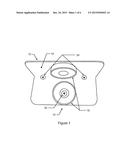
[0006] FIG. 1 is a trimetric view of a first embodiment of the cord bracket showing the inner (door casing facing) surfaces;
[0007] FIG. 2 is a trimetric view of the cord bracket of FIG. 1 shown magnetically adhered to a door casing and having an electrical cord held by the loop of the cord bracket;
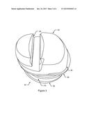
[0008] FIG. 3 is a trimetric view of a second embodiment of the cord bracket;
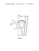
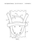
[0009] FIG. 4 is a trimetric view of the cord bracket of FIG. 3 shown magnetically adhered to a door casing and having an electrical cord held by the retention slot of the cord bracket;
[0010] FIG. 5 is a trimetric view of a third embodiment of the cord bracket, and;
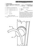
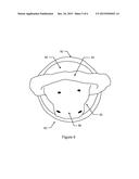
[0011] FIG. 6 is a trimetric view of the cord bracket of FIG. 5 shown magnetically adhered to a door casing and having an electrical cord held by the knob and loop of the cord bracket.
DETAILED DESCRIPTION OF THE INVENTION
[0012] Reference throughout this specification to "one embodiment," "an embodiment," or similar language means that a particular feature, structure, or characteristic described in connection with the embodiment is included in at least one embodiment of the present invention. Thus, appearances of the phrases "in one embodiment," "in an embodiment," and similar language throughout this specification may, but do not necessarily, all refer to the same embodiment.
[0013] Furthermore, the described features, structures, or characteristics of the invention may be combined in any suitable manner in one or more embodiments. In the following description, numerous specific details are included to provide a thorough understanding of embodiments of the invention. One skilled in the relevant art will recognize, however, that the invention can be practiced without one or more of the specific details, or with other methods, components, materials, and so forth. In other instances, well-known structures, materials, or operations are not shown or described in detail to avoid obscuring aspects of the invention.
[0014] In order to facilitate the understanding of the present invention in reviewing the drawings accompanying the specification, a feature list is provided below. It is noted that like features are like numbered throughout all of the figures.
TABLE-US-00001 FEATURE TABLE # Feature # Feature 10 Cord bracket 12 Channel 14 Channel inner surface 16 Channel outer surface 18 Magnet 20 Magnet fastener 22 Loop 24 Loop fastener 26 Electrical cord 28 Door casing 40 Cord bracket 42 Grip 44 Grip retention Slot 46 Grip faying surface 48 Swivel base 50 Magnet 52 Protective coating 54 Electrical cord 56 Door casing 80 Cord bracket 82 Body 84 Body loop 86 Body knob 88 Body faying surface (not shown) 90 Swivel base 92 Magnet 94 Electrical cord 96 Door casing
[0015] Referring now to the drawings, and in particular to FIGS. 1 and 2, a first embodiment of the invention is a cord bracket 10 for use in temporarily securing an electrical cord 26 to a door casing 28 or the like comprising a preferably 90 deg angled channel 12 having a plurality of magnets 18, each of magnets 18 preferably having a protective plastic coating and being connected to an inner surface 14 of channel 12 by means of magnet fasteners 20 and a loop 22 connected to an outer surface 16 of channel 12 by means of loop fasteners 24. In practice, cord bracket 10 is temporarily mounted to door casing 28 by placing cord bracket 10 into contact with door casing 28 such that magnets 18 magnetically adhere to door casing 28. With the cord bracket 10 temporarily mounted to door casing 28, electrical cord 26 of an appliance such as a vacuum cleaner is threaded through loop 22 of the cord bracket 10. With electrical cord 26 threaded through loop 22, the appliance is used with electrical cord 26 of the appliance free to move through loop 22 and yet being prevented from rubbing against door casing 28, thus preventing marring or damaging door casing 28 from rubbing of electrical cord 26 on door casing 28.
[0016] Referring now to the drawings, and in particular to FIGS. 3 and 4, a second embodiment of the invention is a cord bracket 40 for use in temporarily securing an electrical cord 54 to a door casing 56 or the like comprising a grip 42 connected to a swivel base 48 by means of bonding a grip faying surface 46 to swivel base 48 and swivel base 48 connected to a magnet 50 preferably having a protective plastic coating 52 thereon. Grip 42 is preferably constructed of a plastic having a degree of flexibility and includes a retention slot 44 formed therein. In practice, cord bracket 40 is temporarily mounted to door casing 56 by placing cord bracket 40 into contact with door casing 56 such that magnet 50 magnetically adheres to door casing 56. With cord bracket 40 temporarily mounted to door casing 56, electrical cord 54 of an appliance such as a vacuum cleaner is pressed into retention slot 44. With electrical cord 54 retained by retention slot 44, the appliance is used with electrical cord 54 of the appliance free to rotate and yet being prevented from rubbing against door casing 56, thus preventing marring or damaging door casing 56 from rubbing of electrical cord 54 on door casing 56. It is noted that in an alternative embodiment, a suction cup is substituted for magnet 50 such that rather magnetically adhering cord bracket 40 to door casing 56, cord bracket 40 is adhered to door casing 56 by means of a partial vacuum being created between the suction cup and door casing 56. Further, other additional means of securing cord bracket 40 to door casing 56, such as a semi-adhesive putty, are also contemplated.
[0017] Referring now to the drawings, and in particular to FIGS. 5 and 6, a third embodiment of the invention is a cord bracket 80 for use in temporarily securing an electrical cord 94 to a door casing 96 or the like comprising a body 82 connected to a swivel base 90 by means of bonding a body faying surface 88 to swivel base 90 and swivel base 90 connected to a magnet 92 preferably having a protective plastic coating thereon. Body 82 is preferably constructed of a plastic and includes a loop 84 and a knob 86 formed thereon. In practice, cord bracket 80 is temporarily mounted to door casing 96 by placing cord bracket 80 into contact with door casing 96 such that magnet 92 magnetically adheres to door casing 96. With cord bracket 80 temporarily mounted to door casing 96, electrical cord 94 of an appliance such as a vacuum cleaner is threaded through loop 84 of cord bracket 80 and over knob 86 of cord bracket 80. With electrical cord 94 retained by body 82, the appliance is used with electrical cord 94 of the appliance free to rotate and yet being prevented from rubbing against door casing 96, thus preventing marring or damaging door casing 96 from rubbing of electrical cord 94 on door casing 96.
[0018] The present invention may be embodied in other specific forms without departing from its spirit or essential characteristics. The described embodiments are to be considered in all respects only as illustrative and not restrictive. The scope of the invention is, therefore, indicated by the appended claims rather than by the foregoing description. All changes which come within the meaning and range of equivalency of the claims are to be embraced within their scope.
User Contributions:
Comment about this patent or add new information about this topic:
Images included with this patent application:
 |  |
 |  |
 |  |
 |
| Similar patent applications: | |
| Date | Title |
|---|---|
| 2015-12-17 | Optical post mount system and method of use |
| 2015-11-12 | Line clamp assembly and method of use |
| 2015-12-31 | Knuckle bracket and pair of knuckle brackets |
| 2015-12-31 | Cantilever-style wine bucket and bottle holder |
| 2015-12-31 | Multipurpose securing systems, kits and methodologies |
| New patent applications in this class: | |
| Date | Title |
|---|---|
| 2019-05-16 | Pipe support and method |
| 2016-12-29 | Pipe support |
| 2016-05-19 | Display stand |
| 2016-04-28 | Bracket and use |
| 2016-01-07 | Fastening device for fixing a cable |
| New patent applications from these inventors: | |
| Date | Title |
|---|---|
| 2015-09-03 | Toilet having auxiliary discharge path and valve |
| Top Inventors for class "Supports" | |
| Rank | Inventor's name |
|---|---|
| 1 | Jeffrey D. Carnevali |
| 2 | Yun-Lung Chen |
| 3 | Wen-Tang Peng |
| 4 | Zheng-Heng Sun |
| 5 | Zhan-Yang Li |