Patent application title: ELECTRONIC-CIGARETTE FILTER
Inventors:
Samuel Lansing (Fort Lauderdale, FL, US)
IPC8 Class: AA24F4700FI
USPC Class:
131329
Class name: Tobacco tobacco users' appliance
Publication date: 2015-12-24
Patent application number: 20150366265
Abstract:
An electronic-cigarette filter including a tube housing a vaporizing
device, wherein walls of the tube are substantially fluid impermeable.
The electronic-cigarette filter includes a fluid permeable matrix
disposed adjacent to an exterior of the tube and is in fluid
communication with the vaporizing device. The electronic-cigarette filter
includes a vaporizing liquid disposed throughout the matrix. The
electronic-cigarette filter includes a substantially flexible outer
housing enveloping the matrix and the tube. The electronic-cigarette
filter includes a sealing member consisting essentially of a
substantially fluid impermeable material that is shaped and sized to
prevent direct fluid communication between the matrix and the hole of the
mouthpiece.Claims:
1. An electronic-cigarette filter, comprising: a) a tube housing a
vaporizing device, wherein walls of the tube are substantially fluid
impermeable, and wherein the tube includes a first open end and a second
open end each distal from the other; b) a fluid permeable matrix disposed
adjacent to an exterior of the tube and in fluid communication with the
vaporizing device through a region of the tube spaced from the second
open end of the tube; c) a vaporizing liquid disposed throughout the
matrix; d) a substantially flexible outer housing enveloping the matrix
and the tube, the outer housing having a first end including a coupling
structure and a second end, distal from the first end, the second end
including a mouthpiece having a hole therethrough in fluid communication
with the vaporizing device; and e) a sealing member adjacent the second
open end of the tube, the sealing member consisting essentially of a
substantially fluid impermeable material that is shaped and sized to
prevent direct fluid communication between the matrix and the hole of the
mouthpiece.
2. The filter of claim 1, wherein the matrix encircles the tube.
3. The filter of claim 1, wherein the mouthpiece is selectably removably coupled to the outer housing.
4. The filter of claim 1, wherein the sealing member is a nipple extending between the hole of the mouthpiece and the second open end of the tube.
5. The filter of claim 1, wherein the sealing member forms a conduit between the hole of the mouthpiece and the tube.
6. The filter of claim 4, wherein the nipple is fixedly coupled to the mouthpiece and seats into the second open end of the tube when the mouthpiece is coupled to the flexible outer housing.
7. The filter of claim 1, wherein the sealing member is annular and encircles the tube.
8. The filter of claim 1, wherein the matrix is a hollow cylinder.
9. The filter of claim 1, wherein the coupling structure of the first end of the outer housing includes both a physical coupling structure and an electrical coupling structure, each configured to couple to corresponding components of an electronic-cigarette battery housing.
10. The filter of claim 1, wherein the sealing member is highly elastic.
11. An electronic-cigarette filter, comprising: a) a tube housing a vaporizing device, including a first open end and a second open end each distal from the other; b) a fluid permeable matrix disposed adjacent to an exterior of the tube and in fluid communication with the vaporizing device through a region of the tube spaced from the second open end of the tube; c) a vaporizing liquid disposed throughout the matrix; d) a substantially flexible outer housing enveloping the matrix and the tube, the outer housing having a first end and a second end, distal from the first end, the second end including a mouthpiece having a hole therethrough in fluid communication with the vaporizing device; and e) a sealing member adjacent the second open end of the tube, the sealing member consisting essentially of a substantially fluid impermeable material that is shaped and sized to prevent direct fluid communication between the matrix and the hole of the mouthpiece.
12. The filter of claim 11, wherein the matrix is a hollow cylinder that encircles the tube.
13. The filter of claim 12, wherein walls of the tube are substantially fluid impermeable.
14. The filter of claim 13, wherein the sealing member is annular and encircles the tube.
15. The filter of claim 14, wherein the sealing member is flush with the second open end of the tube and is spaced from an interior wall of the mouthpiece.
16. The filter of claim 13, wherein the sealing member forms a conduit between the hole of the mouthpiece and the tube.
17. The filter of claim 13, wherein the sealing member is a nipple extending between the hole of the mouthpiece and the second open end of the tube.
18. The filter of claim 17, wherein the nipple is fixedly coupled to the mouthpiece and seats into the second open end of the tube when the mouthpiece is coupled to the flexible outer housing.
19. An electronic-cigarette filter, comprising: a) a tube housing a vaporizing device, wherein walls of the tube are substantially fluid impermeable, and wherein the tube includes a first open end and a second open end each distal from the other; b) a fluid permeable matrix shaped as a hollow cylinder disposed adjacent to an exterior of the tube, encircling the same, and in fluid communication with the vaporizing device through a region of the tube spaced from the second open end of the tube; c) a vaporizing liquid disposed throughout the matrix; d) a substantially flexible outer housing enveloping the matrix and the tube, the outer housing having a first end including a coupling structure and a second end, distal from the first end, the second end including a mouthpiece having a hole therethrough in fluid communication with the vaporizing device; and e) a sealing member adjacent the second open end of the tube, the sealing member consisting essentially of a substantially fluid impermeable material that is shaped and sized to prevent direct fluid communication between the matrix and the hole of the mouthpiece.
20. The filter of claim 19, wherein the sealing member is selected from the group of sealing members consisting of an annular plug and a seating nipple.
Description:
BACKGROUND OF THE INVENTION
[0001] 1. Field of the Invention
[0002] The present invention relates to electronic-cigarettes, specifically to electronic-cigarette filters configured to give a feel and use similar to actual cigarettes.
[0003] 2. Description of the Related Art
[0004] An electronic-cigarette (e-cig or e-cigarette), personal vaporizer (PV) or electronic nicotine delivery system (ENDS) is generally a battery-powered device which simulates tobacco smoking. It generally uses a heating element known as an atomizer that vaporizes a liquid solution. Some solutions contain a mixture of nicotine and flavorings, while others release a flavored vapor without nicotine.
[0005] Many are designed to simulate smoking implements, such as cigarettes or cigars, in their use and/or appearance, while others are considerably different in appearance. Such will generally include a mouthpiece configured to allow a user to inhale vapor therethrough. True cigarette filters are generally made from cellulose acetate and are of a firm-spongy consistency. Thus, cigarette smokers are used to having a mouthpiece that gives way a little when grasped by the mouth and many e-cigarettes have mouthpieces that are substantially different in look and/or feel when compared to true/traditional cigarettes.
[0006] Some improvements have been made in the field. Examples of references related to the present invention are described below in their own words, and the supporting teachings of each reference are incorporated by reference herein:
[0007] U.S. Pat. No. 4,634,027, issued to Kanarvogel, discloses a liquid dispensing apparatus is provided having a container for storing the liquid to be dispensed, an anti-drip valve cartridge connected to the container and a needle element connected to the valve cartridge. A device is provided for pressurizing the container for the duration of a time interval and for depressurizing the container to atmospheric pressure, simultaneously, with the end of the time interval. The valve cartridge has an outlet portion which sealably connects an outlet opening thereof in registry with the bore of the needle element. A pressure activated poppet valve can be provided in the valve cartridge to seal the outlet opening upon the depressurization of the container. After depressurization, a volume of liquid is left in the needle element which exerts a pressure at the end of the needle element that is less than the incoming atmospheric pressure. As a result, liquid will not drip from the end of the needle element after the depressurization of the container and thus the dispensing of the liquid. An air barrier can be provided in the container to prevent airation of the liquid to be dispensed. Additionally, a liquid induction fitting and a liquid storage tank can be provided for automatic refill of the container.
[0008] U.S. Patent Application Publication No. 2013/0306064, by Thorens et al., discloses an aerosol generating system for heating a liquid aerosol-forming substrate. The system includes an aerosol-forming chamber, and a leakage preventer for preventing or reducing leakage of liquid aerosol condensate from the aerosol generating system. The leakage preventer may include one or more of: at least one cavity in a wall of the aerosol-forming chamber, for collecting droplets of condensed liquid aerosol-forming substrate; at least one hooked member for collecting droplets of condensed liquid aerosol-forming substrate; an impactor for disrupting airflow in the aerosol-forming chamber so as to collect liquid droplets; and a closure member for substantially sealing the aerosol-forming chamber when the aerosol generating system is not in use.
[0009] U.S. Patent Application Publication No. 2013/0192617, by Thompson, discloses a cartomizer for an electronic-cigarette having an elongated, hollow body with a mouthpiece in a first end and a battery coupling in an opposite second end. An atomizing coil is disposed in the body generally perpendicular to a longitudinal axis of the cartomizer and has positive and negative terminal leads pressfit connected to positive and negative terminals separated by an insulative spacer in the battery coupling. A fibrous wick is inserted inside the atomizing coil and a cloth tube is disposed generally parallel to the longitudinal axis of the cartomizer and extends from the atomizing coil to the mouthpiece. A volatile liquid mixture of preferably 80% propylene glycol and 20% veggie glycol with liquid nicotine and/or flavoring is disposed in the body.
[0010] U.S. Patent Application Publication No. 2013/0180533, by Kim et al., discloses a cartridge of electric cigarette for preventing leakage. The cartridge may comprise a storing container 11 to store liquid therein; an extending tube 12 to have a guide tube 121 installed within the storing container 11 and extending in a hollow cylindrical shape, a lower fixing plate 122 coupled to the lower part of the guide tube 121 and secured to the lower part of the storing container 11 and a fixing gap 123 formed at the upper part of the guide tube 121; a guide lid 16 coupled to the upper part of the extending tube 12 and introducing evaporated component; an evaporating unit 17 fixed at the fixing gap 123; and a mouth piece 13 communicating with the guide lid 16 and coupled to the upper part of the storing container 11.
[0011] U.S. Patent Application Publication No. 2013/0160765, by Liu, discloses a mouthpiece device of electronic-cigarette, includes an atomizing device for vaporizing tobacco substance into aerosol, a reservoir for storing tobacco substance and a guiding tube for guiding tobacco substance from the reservoir to the atomizing device, which are set in an shell. The guiding tube has one end inserted in the reservoir and the other end communicated with atomizing device. The mouthpiece device further includes a preheat device for heat solid tobacco substance in the reservoir to generate liquid. The preheat device is set in the end of the reservoir near the guiding tube, and seals solid tobacco substance in the reservoir. The present invention solves existing problems such as fluid leakage, complicate manufacturing, high cost, bad heat insulation and filtering aerosol; and obtains perfect leakage proof, simple manufacturing, lower cost, good heat insulation and well filtering aerosol.
[0012] The inventions heretofore known suffer from a number of disadvantages which include being flimsy, being leaky, being expensive, being difficult to use, being easily breakable, being non-durable, leaking inappropriate and/or dangerous amounts of fluid into the mouth of the user, allowing fluid to leak on the clothing and etc. of the user and thusly causing a mess during use, being difficult to package without risking a leak inside the packaging during storage/transport, and the like.
[0013] What is needed is an electronic-cigarette filter that solves one or more of the problems described herein and/or one or more problems that may come to the attention of one skilled in the art upon becoming familiar with this specification.
SUMMARY OF THE INVENTION
[0014] The present invention has been developed in response to the present state of the art, and in particular, in response to the problems and needs in the art that have not yet been fully solved by currently available electronic-cigarette filters. Accordingly, the present invention has been developed to provide an anti-leaking electronic-cigarette filter that has a feel very similar to that of a traditional cigarette.
[0015] According to one embodiment of the invention, there is an electronic-cigarette filter that may include a tube that may be housing a vaporizing device, wherein walls of the tube may be substantially fluid impermeable, and wherein the tube may include a first open end and a second open end each may be distal from the other.
[0016] The electronic-cigarette filter may include a fluid permeable matrix that may be disposed adjacent to an exterior of the tube and may be in fluid communication with the vaporizing device through a region of the tube spaced from the second open end of the tube. The matrix may encircle the tube. The matrix may be a hollow cylinder.
[0017] The electronic-cigarette filter may include a vaporizing liquid that may be disposed throughout the matrix. The electronic-cigarette filter may include a substantially flexible outer housing that may be enveloping the matrix and the tube, the outer housing may have a first end that may include a coupling structure and a second end, that may be distal from the first end, the second end may include a mouthpiece that may have a hole therethrough that may be in fluid communication with the vaporizing device. The mouthpiece may be selectably removably coupled to the outer housing. The coupling structure of the first end of the outer housing may include both a physical coupling structure and an electrical coupling structure, each configured to couple to corresponding components of an electronic-cigarette battery housing.
[0018] The electronic-cigarette filter may include a sealing member that may be adjacent the second open end of the tube, the sealing member may be consisting essentially of a substantially fluid impermeable material that may be shaped and sized to prevent direct fluid communication between the matrix and the hole of the mouthpiece. The sealing member may be a nipple that may be extending between the hole of the mouthpiece and the second open end of the tube. The sealing member may form a conduit between the hole of the mouthpiece and the tube. The nipple may be fixedly coupled to the mouthpiece and may seat into the second open end of the tube when the mouthpiece is coupled to the flexible outer housing. The sealing member may be annular and may encircle the tube. The sealing member may be highly elastic.
[0019] According to one embodiment of the invention, there is an electronic-cigarette filter that may include a tube that may be housing a vaporizing device. The tube may include a first open end and a second open end each may be distal from the other. Walls of the tube may be substantially fluid impermeable.
[0020] The electronic-cigarette filter may include a fluid permeable matrix that may be disposed adjacent to an exterior of the tube and may be in fluid communication with the vaporizing device through a region of the tube spaced from the second open end of the tube.
[0021] The electronic-cigarette filter may include a vaporizing liquid that may be disposed throughout the matrix. The matrix may be a hollow cylinder that may encircle the tube.
[0022] The electronic-cigarette filter may include a substantially flexible outer housing that may be enveloping the matrix and the tube, the outer housing may have a first end and a second end, that may be distal from the first end, the second end may include a mouthpiece that may have a hole therethrough that may be in fluid communication with the vaporizing device.
[0023] The electronic-cigarette filter may include a sealing member that may be adjacent the second open end of the tube, the sealing member may consist essentially of a substantially fluid impermeable material that may be shaped and sized to prevent direct fluid communication between the matrix and the hole of the mouthpiece. The sealing member may be annular and may encircle the tube. The sealing member may be flush with the second open end of the tube and may be spaced from an interior wall of the mouthpiece. The sealing member may form a conduit between the hole of the mouthpiece and the tube. The sealing member may be a nipple that may be extending between the hole of the mouthpiece and the second open end of the tube. The nipple may be fixedly coupled to the mouthpiece and may seat into the second open end of the tube when the mouthpiece is coupled to the flexible outer housing.
[0024] According to one embodiment of the invention, there is an electronic-cigarette filter that may include a tube that may be housing a vaporizing device, wherein walls of the tube may be substantially fluid impermeable, and wherein the tube may include a first open end and a second open end each may be distal from the other.
[0025] The electronic-cigarette filter may include a fluid permeable matrix that may be shaped as a hollow cylinder that may be disposed adjacent to an exterior of the tube, that may be encircling the same, and may be in fluid communication with the vaporizing device through the first open end of the tube.
[0026] The electronic-cigarette filter may include a vaporizing liquid that may be disposed throughout the matrix.
[0027] The electronic-cigarette may include a substantially flexible outer housing that may be enveloping the matrix and the tube, the outer housing may have a first end that may be including a coupling structure and a second end, that may be distal from the first end, the second end may include a mouthpiece that may be having a hole therethrough in fluid communication with the vaporizing device.
[0028] The electronic-cigarette filter may include a sealing member that may be adjacent the second open end of the tube, the sealing member may consist essentially of a substantially fluid impermeable material that may be shaped and sized to prevent direct fluid communication between the matrix and the hole of the mouthpiece. The sealing member may be selected from the group of sealing members that may consist of an annular plug and a seating nipple.
[0029] Reference throughout this specification to features, advantages, or similar language does not imply that all of the features and advantages that may be realized with the present invention should be or are in any single embodiment of the invention. Rather, language referring to the features and advantages is understood to mean that a specific feature, advantage, or characteristic described in connection with an embodiment is included in at least one embodiment of the present invention. Thus, discussion of the features and advantages, and similar language, throughout this specification may, but do not necessarily, refer to the same embodiment.
[0030] Furthermore, the described features, advantages, and characteristics of the invention may be combined in any suitable manner in one or more embodiments. One skilled in the relevant art will recognize that the invention can be practiced without one or more of the specific features or advantages of a particular embodiment. In other instances, additional features and advantages may be recognized in certain embodiments that may not be present in all embodiments of the invention.
[0031] These features and advantages of the present invention will become more fully apparent from the following description and appended claims, or may be learned by the practice of the invention as set forth hereinafter.
BRIEF DESCRIPTION OF THE DRAWINGS
[0032] In order for the advantages of the invention to be readily understood, a more particular description of the invention briefly described above will be rendered by reference to specific embodiments that are illustrated in the appended drawing(s). It is noted that the drawings of the invention are not to scale. The drawings are mere schematics representations, not intended to portray specific parameters of the invention. Understanding that these drawing(s) depict only typical embodiments of the invention and are not, therefore, to be considered to be limiting its scope, the invention will be described and explained with additional specificity and detail through the use of the accompanying drawing(s), in which:
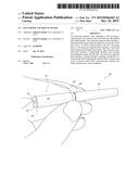
[0033] FIG. 1 is a perspective view of an electronic-cigarette filter coupled to an electronic-cigarette battery housing, according to one embodiment of the invention;
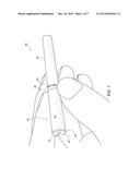
[0034] FIG. 2 is a perspective view of an electronic-cigarette filter, according to one embodiment of the invention;
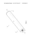
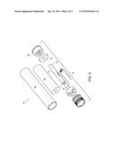
[0035] FIG. 3 is an exploded perspective view of an electronic-cigarette filter, according to one embodiment of the invention;
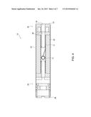
[0036] FIG. 4 is a side elevational cross-sectional view of an electronic-cigarette filter, according to one embodiment of the invention;
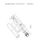
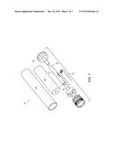
[0037] FIG. 5 is an exploded perspective view of an electronic-cigarette filter, according to one embodiment of the invention;
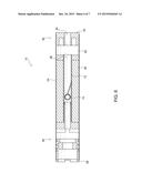
[0038] FIG. 6 is a side elevational cross-sectional view of an electronic-cigarette filter, according to one embodiment of the invention; and
[0039] FIG. 7 is an exploded perspective view of an electronic-cigarette filter, according to one embodiment of the invention.
DETAILED DESCRIPTION OF THE INVENTION
[0040] For the purposes of promoting an understanding of the principles of the invention, reference will now be made to the exemplary embodiments illustrated in the drawing(s), and specific language will be used to describe the same. It will nevertheless be understood that no limitation of the scope of the invention is thereby intended. Any alterations and further modifications of the inventive features illustrated herein, and any additional applications of the principles of the invention as illustrated herein, which would occur to one skilled in the relevant art and having possession of this disclosure, are to be considered within the scope of the invention.
[0041] Reference throughout this specification to an "embodiment," an "example" or similar language means that a particular feature, structure, characteristic, or combinations thereof described in connection with the embodiment is included in at least one embodiment of the present invention. Thus, appearances of the phrases an "embodiment," an "example," and similar language throughout this specification may, but do not necessarily, all refer to the same embodiment, to different embodiments, or to one or more of the figures. Additionally, reference to the wording "embodiment," "example" or the like, for two or more features, elements, etc. does not mean that the features are necessarily related, dissimilar, the same, etc.
[0042] Each statement of an embodiment, or example, is to be considered independent of any other statement of an embodiment despite any use of similar or identical language characterizing each embodiment. Therefore, where one embodiment is identified as "another embodiment," the identified embodiment is independent of any other embodiments characterized by the language "another embodiment." The features, functions, and the like described herein are considered to be able to be combined in whole or in part one with another as the claims and/or art may direct, either directly or indirectly, implicitly or explicitly.
[0043] As used herein, "comprising," "including," "containing," "is," "are," "characterized by," and grammatical equivalents thereof are inclusive or open-ended terms that do not exclude additional unrecited elements or method steps. "Comprising" is to be interpreted as including the more restrictive terms "consisting of" and "consisting essentially of."
[0044] FIG. 1 is a perspective view of an electronic-cigarette filter coupled to an electronic-cigarette battery housing, according to one embodiment of the invention. There is shown an electronic-cigarette filter 10 coupled to an electronic-cigarette battery housing 40 to provide an electronic-cigarette 50.
[0045] The illustrated electronic-cigarette filter 10 is configured to store a vaporizing liquid therein for vaporizing and inhalation by a user. The illustrated electronic-cigarette filter 10 is coupled to an electronic-cigarette batter housing 40 to provide an electronic-cigarette 50 for inhalation of the vaporizing liquid.
[0046] The illustrated electronic-cigarette filter 10 includes a tube housing a vaporizing device, wherein walls of the tube are substantially fluid impermeable, and wherein the tube includes a first open end and a second open end each distal from the other.
[0047] The electronic-cigarette filter 10 includes a substantially flexible outer housing 24 enveloping a matrix and a tube of the filter 10. The outer housing 24 is configured to secure the components and modules of the filter 10 therein. The outer housing 24 includes a first end 26 having a coupling structure 28 and a second end 30, distal from the first end 26. The second end 30 includes a mouthpiece 32 having a hole 34 therethrough that is in fluid communication with a vaporizing device, which is disposed within the outer housing 24. The mouthpiece 32 is selectably removably coupled to the outer housing 24. The coupling structure 28 of the first end 26 of the outer housing 24 includes both a physical coupling structure and an electrical coupling structure, each configured to couple to corresponding components of an electronic-cigarette battery housing 40. This is generally present in the form of a screw-type interface that physically couples the structures together such that when mated, electrical contacts are disposed against one another, thereby allowing current to flow therethrough when desired.
[0048] The illustrated electronic-cigarette filter 10 is configured to provide a non-leaking filter for e-cigarettes. The electronic-cigarette filter 10 provides for airflow through the filter 10 without direct access between the matrix storing the liquid and the exiting airflow, thereby eliminating any liquid from leaking or entering the user's mouth during inhalation or use of the electronic-cigarette. This is particularly important wherein the housing of the filter is substantially flexible, such as but not limited to having flexing characteristics similar to that of a traditional cigarette filter. Wherein the exiting airflow path is not appropriately shielded from the stored vaporizing liquid, such liquid may collect within the airflow path and/or may leak into the path and thus be taken in orally by the user. Vaporization liquid is generally too concentrated to be comfortably taken orally and may pose risks to the user. Even wherein there is shielding between the airflow path and the stored vaporization liquid, if the filter is substantially flexible and then is bitten or even gripped firmly between the lips, the airflow path may distort and the shielding thereof may also distort, thus resulting in undesired pooling or leaking of the vaporization liquid.
[0049] Having an effectively-seamless airflow chamber that goes through the refill filter 10, all the way from the point where the user puts the e-cigarette 50 to their mouth to where the filter 10 attaches to the battery assembly 40 reduces leaking and allows the user to grip and even bite down on the filter without causing leakage. There may be an internal nipple molded with the mouthpiece that seals the gap between the mouthpiece and the heating element holding tube that goes through the center of the filter 10, thus sealing the airflow path even when the exterior of the filter is under pressure, e.g. from a user biting down on the filter. There may be a second nipple where the filter attaches to the battery assembly 40 that seals against the outer tube so that the vaporizing liquid cannot leak into the tube or out therefrom.
[0050] FIG. 2 is a perspective view of an electronic-cigarette filter, according to one embodiment of the invention. There is shown an electronic-cigarette filter 10 including a substantially flexible outer housing 24 having a first end 26 and a second end 30.
[0051] The illustrated electronic-cigarette filter 10 includes a substantially flexible outer housing 24 configured to envelop a matrix and a tube. The substantially flexible outer housing 24 is configured to secure and support the matrix and the tube disposed therein. The outer housing 24 includes a first end 26 including a coupling structure 28 and a second end 30, distal from the first end 26. The second end 30 includes a mouthpiece 32 having a hole therethrough that is in fluid communication with a vaporizing device that is disposed within the tube and the outer housing 24. The coupling structure 28 of the first end 26 of the outer housing 24 includes both a physical coupling structure 40 and an electrical coupling structure 42, each configured to couple to corresponding components of an electronic-cigarette battery housing.
[0052] Looking to FIGS. 3 and 4, FIG. 3 is an exploded perspective view of an electronic-cigarette filter, according to one embodiment of the invention and FIG. 4 is a cross-sectional view of an electronic cigarette filter, according to one embodiment of the invention. There is shown an electronic-cigarette filter 10 including a tube 12, a vaporizing device 14, a substantially flexible outer housing 24, a fluid permeable matrix 20 (fluid storage matrix), and a sealing member 36.
[0053] The illustrated electronic-cigarette filter 10 includes a tube 12 housing a vaporizing device 14, wherein walls of the tube 12 are substantially fluid impermeable, and wherein the tube 12 includes a first open end 16 and a second open end 18 each distal from the other. Generally the tube is of a plastic or metal that is sufficiently strong to maintain an air channel even when the matrix/housing is compressed and that is substantially fluid impermeable. The illustrated tube also includes apertures for access by the vaporizing device which allows fluid to enter therethrough and to be vaporized while inside the tube. The tube also protects and houses the vaporizing device.
[0054] The electronic-cigarette filter 10 includes a fluid permeable matrix 20 disposed adjacent to an exterior of the tube 12 (it envelopes the tube, thus providing fluid storage adjacent thereto) and is in fluid communication with the vaporizing device 14 through the side apertures of the tube 12. The fluid permeable matrix 20 may be a cylinder of woven fibers or a sponge-like material configured to hold a quantity of fluid therein. The matrix has a hole therethrough such that it may be disposed about and substantially encircle the tube. The matrix is generally flexible so that it contributes to the overall feel of the structure being similar to that of a traditional cigarette filter. Indeed, the matrix may be of substantially similar materials to those used in traditional filters, though modified to better contain fluids therein. The fluid permeable matrix 20 is adjacent to an exterior of the tube 12 and is in fluid communication with the vaporizing device 14 through a region of the tube spaced from the second open end of the tube. The electronic-cigarette filter 10 includes a vaporizing liquid disposed throughout the matrix.
[0055] The electronic-cigarette filter 10 includes a substantially flexible outer housing 24 enveloping the matrix and the tube 12. Such will generally be a thin cylinder made of a flexible and fluid impermeable material, such as but not limited to plastic. The outer housing 24 includes a first end 26 having a coupling structure 28 and a second end 30, distal from the first end 26. The second end 30 includes a mouthpiece 32 having a hole therethrough that is in fluid communication with the vaporizing device 14. The mouthpiece 32 is selectably removably coupled to the outer housing 24. The coupling structure 28 of the first end 26 of the outer housing 24 includes both a physical coupling structure and an electrical coupling structure, each configured to couple to corresponding components of an electronic-cigarette battery housing. The illustrated outer housing envelops the matrix and the tube 12, the outer housing 24 having a first end 26 and a second end 30, distal from the first end 26, the second end 30 includes a mouthpiece 32 having a hole 34 therethrough that is in fluid communication with the vaporizing device 14.
[0056] The illustrated electronic-cigarette filter 10 includes a sealing member 36 adjacent the second open end 18 of the tube 12, the sealing member 36 consisting essentially of a substantially fluid impermeable material that is shaped and sized to prevent direct fluid communication between the matrix and the hole of the mouthpiece 32. The illustrated sealing member 36 is a flanged nipple extending between the hole of the mouthpiece 32 and the second open end 18 of the tube 12. The flanged region of the illustrated flanged nipple abuts the mouthpiece and is adjacent thereto without a gap therebetween. The sealing member 36 forms a conduit 38 between the hole of the mouthpiece 32 and the tube 12. The nipple is fixedly coupled to the mouthpiece 32 and seats into the second open end 18 of the tube 12 when the mouthpiece 32 is coupled to the flexible outer housing 24. The sealing member 36 is cylindrical and friction fits inside the tube 12 in a manner that prevents fluid from the matrix from entering the airflow pathway towards the mouthpiece. The sealing member 36 is highly elastic such that it may seat well against adjacent structures and seal the same with a fluid impermeable seal.
[0057] In one non-limiting embodiment, there is an electronic-cigarette filter 10 which includes a sealing member 36 adjacent the second open end 18 of the tube 12, the sealing member 36 consists essentially of a substantially fluid impermeable material that is shaped and sized to prevent direct fluid communication between the matrix and the hole of the mouthpiece 32. The sealing member 36 forms a conduit 38 between the hole of the mouthpiece 32 and the tube 12. The sealing member 36 is a nipple extending between the hole of the mouthpiece 32 and the second open end 18 of the tube 12. The nipple is fixedly coupled to the mouthpiece 32 and seats into the second open end 18 of the tube 12 when the mouthpiece 32 is coupled to the flexible outer housing 24.
[0058] Advantageously, the illustrated filter provides for a traditional look and feel while preventing leakage of fluid from the interior of the filter even when the filter is bitten by the user and/or otherwise compressed. Typical filters having similar structure will crack or otherwise open and the matrix, being asymmetrically compressed, will pool fluid near regions of the cracking/opening. Other non-leaking filters tend to be very rigid or have structures that produce a look and/or feel that is not traditional.
[0059] In one non-limiting embodiment, the electronic-cigarette filter 10 includes a sealing member 36 adjacent the second open end 18 of the tube 12, the sealing member 36 consists essentially of a substantially fluid impermeable material that is shaped and sized to prevent direct fluid communication between the matrix and the hole of the mouthpiece 32. The sealing member 36 is selected from the group of sealing members that consist of an annular plug and a seating nipple.
[0060] Looking to FIGS. 5-7, FIGS. 5 and 7 are exploded perspective views of an electronic-cigarette filter, according to one embodiment of the invention and FIG. 6 is a cross-sectional view of an electronic cigarette filter, according to one embodiment of the invention. There is shown an electronic-cigarette filter 10 including a tube 12, a vaporizing device 14, a substantially flexible outer housing 24, a fluid permeable matrix 20 (fluid storage matrix), and a sealing member 52.
[0061] The illustrated electronic-cigarette filter 10 includes a tube 12 housing a vaporizing device 14, wherein walls of the tube 12 are substantially fluid impermeable, and wherein the tube 12 includes a first open end 16 and a second open end 18 each distal from the other. Generally the tube is of a plastic or metal that is sufficiently strong to maintain an air channel even when the matrix/housing is compressed and that is substantially fluid impermeable. The illustrated tube also includes apertures for access by the vaporizing device which allows fluid to enter therethrough and to be vaporized while inside the tube. The tube also protects and houses the vaporizing device.
[0062] The electronic-cigarette filter 10 includes a fluid permeable matrix 20 disposed adjacent to an exterior of the tube 12 (it envelopes the tube, thus providing fluid storage adjacent thereto) and is in fluid communication with the vaporizing device 14 through the side apertures of the tube 12. The fluid permeable matrix 20 may be a cylinder of woven fibers or a sponge-like material configured to hold a quantity of fluid therein. The matric has a hole therethrough such that it may be disposed about and substantially encircle the tube. The matrix is generally flexible so that it contributes to the overall feel of the structure being similar to that of a traditional cigarette filter. Indeed, the matrix may be of substantially similar materials to those used in traditional filters, though modified to better contain fluids therein. The fluid permeable matrix 20 is adjacent to an exterior of the tube 12 and is in fluid communication with the vaporizing device 14 through a region of the tube spaced from the second open end of the tube. The electronic-cigarette filter 10 includes a vaporizing liquid disposed throughout the matrix.
[0063] The electronic-cigarette filter 10 includes a substantially flexible outer housing 24 enveloping the matrix and the tube 12. Such will generally be a thin cylinder made of a flexible and fluid impermeable material, such as but not limited to plastic. The outer housing 24 includes a first end 26 having a coupling structure 28 and a second end 30, distal from the first end 26. The second end 30 includes a mouthpiece 32 having a hole therethrough that is in fluid communication with the vaporizing device 14. The mouthpiece 32 is selectably removably coupled to the outer housing 24. The coupling structure 28 of the first end 26 of the outer housing 24 includes both a physical coupling structure 42 and an electrical coupling structure 44, each configured to couple to corresponding components of an electronic-cigarette battery housing. The illustrated outer housing envelops the matrix and the tube 12, the outer housing 24 having a first end 26 and a second end 30, distal from the first end 26, the second end 30 includes a mouthpiece 32 having a hole therethrough that is in fluid communication with the vaporizing device 14.
[0064] The illustrated electronic-cigarette filter 10 includes a sealing member 52 adjacent the second open end 18 of the tube 12, the sealing member 52 consisting essentially of a substantially fluid impermeable material that is shaped and sized to prevent direct fluid communication between the matrix and the hole of the mouthpiece 32. The illustrated sealing member 52 is an annular seal forming a flange about the second end of the tube, thus sealing in the matrix and the fluid therewith. The sealing member 52 forms a boundary wall that allows for a conduit 38 between the hole of the mouthpiece 32 and the tube 12 to persist. There is a spacing 62 between the annular seal 52 and the mouthpiece 32, yet fluid is not able to pool therein because of the seal. The annular seal is fixedly coupled to and between the tube and housing, thereby preventing fluid from the matrix from entering the airflow pathway towards the mouthpiece. The sealing member 52 is highly elastic such that it may seat well against adjacent structures and seal the same with a fluid impermeable seal while not negatively impacting the feel of the filter when used.
[0065] In one non-limiting embodiment, the electronic-cigarette filter 10 includes a sealing member 52 adjacent the second open end 18 of the tube 12, the sealing member 52 consists essentially of a substantially fluid impermeable material that is shaped and sized to prevent direct fluid communication between the matrix and the hole of the mouthpiece 32. The sealing member 36 is annular and encircles the tube 12. The sealing member 52 is flush with the second open end 18 of the tube 12 and is spaced from an interior wall of the mouthpiece 32. The sealing member 52 forms a conduit between the hole of the mouthpiece 32 and the tube 12.
[0066] In one embodiment of the invention, FIG. 7 illustrates an electronic-cigarette filter 10 which includes a sealing member coupled to the mouthpiece 32 adjacent the second open end 18 of the tube 12, the sealing member consists essentially of a substantially fluid impermeable material that is shaped and sized to prevent direct fluid communication between the matrix and the hole of the mouthpiece 32. The sealing member forms a conduit between the hole of the mouthpiece 32 and the tube 12. The sealing member is a nipple extending from the mouthpiece 32 and the second open end 18 of the tube 12. The nipple is fixedly coupled to the mouthpiece 32 and seats into the second open end 18 of the tube 12 when the mouthpiece 32 is coupled to the flexible outer housing 24.
[0067] Advantageously, the illustrated filter provides for a traditional look and feel while preventing leakage of fluid from the interior of the filter even when the filter is bitten by the user and/or otherwise compressed. Typical filters having similar structure will crack or otherwise open and the matrix, being asymmetrically compressed, will pool fluid near regions of the cracking/opening. Other non-leaking filters tend to be very rigid or have structures that produce a look and/or feel that is not traditional. Further, the sealing structures described herein are easy to manufacture and assemble, while still providing great feel, flexibility, comfort to the users.
[0068] It is understood that the above-described embodiments are only illustrative of the application of the principles of the present invention. The present invention may be embodied in other specific forms without departing from its spirit or essential characteristics. The described embodiment is to be considered in all respects only as illustrative and not restrictive. The scope of the invention is, therefore, indicated by the appended claims rather than by the foregoing description. All changes which come within the meaning and range of equivalency of the claims are to be embraced within their scope.
[0069] For example, although the figures illustrate specific shapes of sealing members, it is understood that wherein the tube, mouthpiece and/or the housing vary in shape, the sealing member may vary similarly in shape. As a non-limiting example, wherein the tube is square in cross-section, the sealing member may be similarly shaped at regions where contact with the tube is made.
[0070] Additionally, although the figures illustrate two variations of sealing members, it is understood that the different types of sealing members which may be utilized are plethoric and that variations of such include different blends of the illustrated structure.
[0071] Finally, it is envisioned that the components of the device may be constructed of a variety of materials, such as but not limited to plastics, rubber, woven fibers, metals, ceramics, composites and the like and combinations thereof.
[0072] Thus, while the present invention has been fully described above with particularity and detail in connection with what is presently deemed to be the most practical and preferred embodiment of the invention, it will be apparent to those of ordinary skill in the art that numerous modifications, including, but not limited to, variations in size, materials, shape, form, function and manner of operation, assembly and use may be made, without departing from the principles and concepts of the invention as set forth in the claims. Further, it is contemplated that an embodiment may be limited to consist of or to consist essentially of one or more of the features, functions, structures, methods described herein.
User Contributions:
Comment about this patent or add new information about this topic:
| People who visited this patent also read: | |
| Patent application number | Title |
|---|---|
| 20200267425 | METHOD FOR INTELLIGENT BUFFERING FOR OVER THE TOP (OTT) VIDEO DELIVERY |
| 20200267424 | IMAGE TRANSMISSION DEVICE, IMAGE TRANSMISSION METHOD, IMAGE RECEPTION DEVICE, AND IMAGE RECEPTION METHOD |
| 20200267423 | METHOD FOR INITIATING A TRANSMISSION OF A STREAMING CONTENT DELIVERED TO A CLIENT DEVICE AND ACCESS POINT FOR IMPLEMENTING THIS METHOD |
| 20200267422 | Complementary Transport Stream |
| 20200267421 | TIME-BASED CONTENT SYNCHRONIZATION |
Images included with this patent application:
 |  |
 |  |
 |  |
 |  |
| Similar patent applications: | |
| Date | Title |
|---|---|
| 2015-11-26 | Degradable cigarette filter |
| 2016-03-17 | Electronic cigarette |
| 2016-04-14 | Electronic cigarette |
| 2016-04-21 | Electronic cigarette |
| 2016-04-21 | Electronic cigarette |
| New patent applications in this class: | |
| Date | Title |
|---|---|
| 2022-05-05 | Aerosol delivery device having a resonant transmitter |
| 2022-05-05 | Aerosol generating device and operating method therefor |
| 2022-05-05 | Electronic smoking device |
| 2022-05-05 | Flavor dispenser apparatus |
| 2022-05-05 | Electronic cigarette atomization assembly and manufacturing method therefor |
| Top Inventors for class "Tobacco" | |
| Rank | Inventor's name |
|---|---|
| 1 | Qiuming Liu |
| 2 | Munmaya K. Mishra |
| 3 | Qiuming Liu |
| 4 | Stephen Benson Sears |
| 5 | William R. Sweeney |