Patent application title: MULTI-SPORT INFLATABLE CAGE/STRUCTURE
Inventors:
Anthony Begando (Milton, GA, US)
Sherri Burdeshaw (Canton, GA, US)
IPC8 Class: AA63B6900FI
USPC Class:
473422
Class name: Games using tangible projectile playing field or court game; game element or accessory therefor other than projector or projectile, per se practice or training device
Publication date: 2015-11-12
Patent application number: 20150321061
Abstract:
The disclosure generally relates to a system for providing a structure
for multi-sport practice and/or training activities. The system can
include one or more modules comprising a series of inflatable sections
and one or more netting panels releasably coupled to the sections of the
one or more inflatable modules. Upon inflation of the inflatable
sections, the one or more modules can be erected into a substantially
self-supporting structure, which can define an interior practice space
configured for performing selected sports practice and/or other training
activities therein.Claims:
1. A system for providing a collapsible, portable structure for
multi-sport practice and/or training activities, comprising: at least one
module comprising a series of inflatable sections connected together; and
at least one netting panel releasably coupled to at least one of the
sections of the at least one inflatable module; wherein, upon inflation
of the inflatable sections, the at least one module is erected into a
substantially self-supporting structure defining an interior practice
space, the interior practice space configured for performing one or more
selected sports practice and/or training activities therein.
2. The system according to claim 1, wherein the at least one module is configured to be connected in series with one or more additional modules to create a variable length structure accommodating the one or more selected sports practice and/or training activities.
3. The system according to claim 2, wherein the at least one module is connected to the one or more additional modules by one or more module interconnects; and wherein the at least one netting panel is configured to be connectable to one or more additional netting panels of the one or more additional modules.
4. The system according to claim 1, wherein the at least one inflatable module comprises a horseshoe, semi-circular, square, oval, or rectangular shape, configured and dimensioned to facilitate the one or more selected sports practice and/or training activities.
5. The system according to claim 1, wherein the inflatable sections of at least one module each comprises a substantially airtight, puncture and weather resistant material.
6. The system according to claim 5, wherein the sections each comprise a polyvinyl chloride impregnated material fabricated into a substantially cylindrical beam.
7. The system according to claim 1, wherein the netting panel applies a tension to the at least one section of the module, and wherein altering a tension force of the at least one netting panel changes the rigidity of the at least one inflatable module.
8. The system according to claim 1, further comprising a door panel extending across an open end of the interior practice space, and wherein the door panel is configured to provide access therethrough and into the interior practice space.
9. The system according to claim 1, wherein the at least one netting panel comprises a mesh material having a substantially triangular, diamond, or square shaped pattern, and the at least one netting panel is configured to substantially reduce rebound of objects impacting the at least one netting panel during the one or more selected sports practice and/or training activities.
10. The system according to claim 1, wherein the inflatable sections of the at least one module comprise a front section, a rear section, a first side and a second side, each of the sections connected to each other, and further comprising netting panels releasably connected to each of the front and rear sections of the module.
11. The system according to claim 10, wherein the front and rear sections each comprise a plurality of spaced beams defining open areas therebetween and connected to each other at a plurality of joints, each having a width of between about 1.5 in. and about 4 in.
12. The system according to claim 11, wherein the plurality of joints comprise heat-welded seams.
13. The system according to claim 1, wherein at least one of the inflatable sections of the at least one module includes a pressure release valve.
14. The system according to claim 1, wherein the at least one netting panel comprises one or more panel seams, a netting material disposed between an inner fabric part and an outer fabric part, and having a reinforcing cording woven therein, one or more grommets attached to the inner fabric part, and one or more attachment devices attached to the outer fabric part.
15. A module for forming a multi-sport practice and/or training system, comprising: a front section, a rear section and at least one side section connected together and each including a plurality of inflatable structural beams; and one or more netting panels releasably mounted to at least one of the front, rear and side sections; wherein inflation of the front, rear and at least one side section defines a structural frame having sufficient rigidity and weight to enable the structural frame to be substantially self-supported and comprising an interior practice space configured for performing selected sports practice and/or training activities.
16. The module according to claim 15, further comprising tie down locations arranged along the front, rear and/or side sections and configured for attaching a weight to provide additional stability to the module.
17. The module according to claim 15, wherein the plurality of inflatable structural beams define open areas therebetween and are connected to each other at a plurality of joints, each joint comprising a heat-welded seam having a width of between about 1.5 in. to about 4 in.
18. The module according to claim 15, wherein the plurality of inflatable structural beams of the front and/or side section comprise at least four inflatable structural beams, including first and second inflatable structural beams disposed parallel to each other, third and fourth inflatable structural beams each disposed at an angle with respect to the first and second inflatable structural beams.
19. The module according to claim 15, further comprising a door panel connected to one of the front or rear sections, extending across an opening therein, wherein the door panel is configured to provide access therethrough and into the interior practice space, and comprises at least one rounded interior corner.
Description:
CROSS REFERENCE TO RELATED APPLICATIONS
[0001] The present patent application is a formalization of previously filed, co-pending U.S. Provisional Patent Application Ser. No. 61/990,279, filed May 8, 2014 by the inventors named in the present application. This patent application claims the benefit of the filing date of this cited Provisional Patent Application according to the statutes and rules governing provisional patent applications, particularly 35 U.S.C. §119(e), and 37 C.F.R. §§1.78(a)(3) and 1.78(a)(4). The specification and drawings of the Provisional Patent Application referenced above are specifically incorporated herein by reference as if set forth in their entirety.
FIELD OF DISCLOSURE
[0002] The present disclosure generally relates to an air-sealed, multi-sport practice system, and more specifically, to an inflatable enclosure system for use in practice of multiple, different sports or other activities.
BACKGROUND OF INVENTION
[0003] With the emphasis on fitness and sports today, more and more children and adults are playing sports such as baseball, softball, tennis, golf, lacrosse, soccer, etc. However, with such increased participation has come an increased demand and usage for parks, and practice spaces and structures, which often are limited in their availability. Also, due to size and use constraints, many practice facilities generally are formed as substantially permanent structures that typically cannot be moved and/or easily reconfigured for uses other than their intended purpose. Such permanent structures further typically occupy large amounts of space and are frequently subjected to vandalism when unattended. In addition, in places such as inner city public schools with limited playground/gym space, having multiple, large permanent practice structures are not practical or economical to maintain, thus offering few options for kids to practice different sports. Currently there do exist portable cages, including metal frame cages which, however, generally are very heavy and can be difficult to transport and assemble; and inflatable practice structures that, while potentially easier to erect, generally lack stability and are too small for multi-sport use.
[0004] Consequently, there exists a need for a practice enclosure or system that is highly configurable for multi-sport uses, which is portable and requires minimal storage space, and which further addresses the foregoing and other related and unrelated problems in the art.
SUMMARY OF DISCLOSURE
[0005] In one embodiment, the present disclosure generally relates to an enclosure system utilizing one or more air-sealed, inflatable modules or practice structures supporting and/or enabling practice of numerous different sports including, but not limited to: baseball, softball, lacrosse, golf, hockey, field hockey, soccer, football, tennis and cricket. The modules can be of several different sizes and configured for a desired use/sport, including being fitted with adjustable and reconfigurable interior netting structures and/or other accessory panels, as well as allowing for netting or accessory panels to be mounted at various locations. Furthermore, each module can be interconnected with additional modules to create a variable length structure accommodating multiple applications, including enabling use by multiple users practicing different sports. Modules can be inflated and put to use preferably within about 5-10 minutes, depending on size requirements, and then can be deflated and stored in a generally similar timeframe. The compact nature of the deflated modules allows users to transport and store the modules with minimal footprint and storage requirements.
[0006] The module structures typically can be constructed of a high strength material that can be substantially sealed to prevent air leakage, and which can be substantially resistant to impact, puncture, heat and UV-rays. For example, a heavy duty PVC impregnated material is one type of material that can be used, although other materials also can be used, with the modules being fabricated with a series of cylindrical beams, which can be connected or affixed together to form the module structures themselves. The joints within the structure can be formed using heat-welded or other durable but flexible seams, which form a strong, durable and substantially air tight bond that allows use in both indoor and outdoor environments. The modules thus generally are substantially completely airtight and sealed so that when inflated, they will be provided with an inherent rigidity and structural integrity, and a desired weight balance as needed to support the netting and accessories within the system without necessarily requiring additional, separate supports. However the modules also can be provided with connector straps for tie downs and/or weighted bags or containers for added security during certain weather conditions. As such, each module can be inflated, put to use, and stored, with minimal configuration and assembly.
[0007] Additional features, advantages, and embodiments of the disclosure may be set forth or apparent from consideration of the following detailed description, drawings, and claims. Moreover, it is to be understood that both the foregoing summary of the disclosure and the following detailed description are exemplary and intended to provide further explanation without limiting the scope of the disclosure as claimed.
BRIEF DESCRIPTION OF THE DRAWINGS
[0008] The accompanying drawings, which are included to provide a further understanding of the invention, are incorporated in and constitute a part of this specification, illustrate embodiments of the invention, and together with the detailed description, serve to explain the principles of the invention. No attempt is made to show structural details of the invention in more detail than may be necessary for a fundamental understanding of the invention and the various ways in which it may be practiced. In addition, it will be understood by those skilled in the art that the embodiments of the invention and the various features thereof discussed below are explained in detail with reference to non-limiting embodiments and examples that are described and/or illustrated in the accompanying drawings. It should be noted that the features illustrated in the drawings are not necessarily drawn to scale, and features of one embodiment may be employed with other embodiments as the skilled artisan would recognize, even if not explicitly stated herein. Descriptions of certain components and processing techniques further may be omitted so as to not unnecessarily obscure the embodiments of the invention.
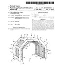
[0009] FIG. 1 is a perspective view of a first example embodiment of the multi-sport practice structure or enclosure according to the principles of the present invention.
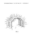
[0010] FIG. 2A is a perspective view of the multi-sport practice structure or enclosure of FIG. 1.
[0011] FIG. 2B is a front view of the multi-sport practice structure or enclosure of FIG. 1.
[0012] FIG. 2C is a top view of the multi-sport practice structure or enclosure of FIG. 1.
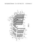
[0013] FIG. 3 is a perspective view of a second example embodiment of the multi-sport practice structure or enclosure according to the principles of the present invention.
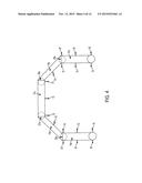
[0014] FIG. 4 is a front view of the multi-sport practice structure or enclosure of FIGS. 1 and 3.
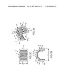
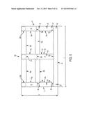
[0015] FIG. 5 is a side exterior view of the multi-sport practice structure or enclosure of FIGS. 1 and 3.
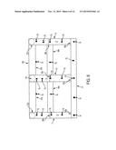
[0016] FIG. 6 is a side interior view of the multi-sport practice structure or enclosure of FIGS. 1 and 3.
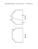
[0017] FIG. 7A is a front view of an example embodiment of an accessory panel arrangement according to the principles of the present invention.
[0018] FIG. 7B is a front view of a third example embodiment of the accessory panel seam and an accessory panel according to the principles of the present invention.
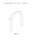
[0019] FIG. 7C is a perspective view of an interconnect panel according to the principles of the present invention.
[0020] FIG. 8 is a detailed view of one exemplary embodiment of an attachment means according to the principles of the present invention.
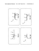
[0021] FIG. 9A is a detailed view of one example embodiment of an accessory panel seam according to the principles of the present invention.
[0022] FIG. 9B is a detailed view of one example embodiment of a continuous panel seam according to the principles of the present invention.
[0023] FIG. 9C is a detailed view of one example embodiment of a terminal panel seam according to the principles of the present invention.
[0024] FIG. 10 is a front view of an accessory panel seam attached to the multi-sport practice structure or enclosure as shown in FIGS. 1 and 3.
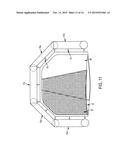
[0025] FIG. 11 is a front view of the opposing panel netted access door of FIG. 11 attached to the accessory panel seam, and thereby to the multi-sport practice structure or enclosure as shown in FIGS. 1 and 3.
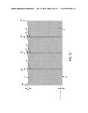
[0026] FIG. 12 is a side view of a netting panel and accessory panel seams according to the principles of the present disclosure.
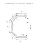
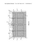
[0027] FIG. 13 is a side interior view of the main module netting attached to the multi-sport practice structure or enclosure as shown in FIGS. 1 and 3.
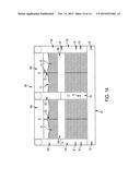
[0028] FIG. 14 is a side exterior view of the main module netting attached to the multi-sport practice structure or enclosure.
DETAILED DESCRIPTION OF INVENTION
[0029] Referring now to the drawings in which like numerals indicate like parts throughout the several views, FIGS. 1-14 show a multi-sport practice system or enclosures, generally indicated at 1, for athletes or kids to practice and/or partake in numerous sports related or other activities, which can include but are not limited to: baseball, softball, lacrosse, golf, hockey, field hockey, soccer, football, tennis and cricket. According to embodiments of the present application, the multi-sport system 1 generally can have one or more inflatable modules 5 defining an interior 3 providing a practice or activity space/area that can be configured for use in performing or practicing a desired sport or other activity, and which modules further can be interconnected together with additional modules to create a variable length structure accommodating multiple applications. The one or more inflatable modules 5 can further be connected to one or more netting panels 67, which may catch or otherwise absorb energy from balls or other objects used in the sports related and/or other activities and may also provide additional rigidity to the one or more modules 5.
[0030] In one illustrative embodiment, the module 5 can include a top section 6, a front section 7, a rear section 9, a first side 8, a second side 10 defined by tubular module structures (e.g., beams) 11, and generally defining, for example, a three dimensional horseshow, semicircular, square, oval, and/or rectangular shape and/or any other shape suitable for use in a multi-sport practice system and/or cage/structure. Each of the module structures 11 generally will be constructed of a heavy duty, substantially air-tight material, which can be highly durable, as well as substantially puncture and weather resistant. For example, each of the module structures 11 can be constructed from a PVC impregnated material fabricated into cylindrical beams.
[0031] As shown in FIGS. 1 and 2A-2C, in one embodiment the front section 7 of the module may comprise five beams 13a, 15a, 17a, 19a, 21a. Beams 13a and 21a can be parallel and extend vertically from the ground; and beams 15a and 19a can be connected to 13a and 21a at joints 23a, 25a, respectively, and angled 135 degrees from beams 13a and 21a; beam 17a generally can be parallel to the ground and connected to beams 15a and 19a at joints 27a, 29a. In the illustrated embodiment, the features of the rear section 9 of the module can include beams 13b, 15b, 17b, 19b, 21b and the joints 23b, 25b, 27b, 29b that can generally be a mirror-image of the corresponding beams and joints of the front section 7. Corresponding components (e.g., beams, joints, attachment features, etc.) have been designated by corresponding reference numbers that differ by the "a" or "b" suffix, with the "a" components corresponding to the front section 7 and the "b" components corresponding to the rear section 9 of the module 5.
[0032] In addition, the front section 7 and rear section 9 may have a width "w" of about 204 in. and a height "h" of about 144 in. The height "h" and width "w" of the front section 7 may correspond to the overall height "h" and width "w" of the module 5. Further, the beams 13a/b, 15a/b, 17a/b, 19a/b, 21a/b may each have a length between about 60 in. to about 100 in., which, for example, may include between about 80 in. to about 90 in. In the illustrated embodiment the length of beams 13a/b and 21a/b can be about 82 in. and beams 17a/b can be about 88 in. The beams further can have a radius of about 6 in. However, the radius, length, angle, size and amount of beams are not limited to these specific dimensions, and, as understood from the disclosure, may be more or less depending on the application of the system.
[0033] The front and rear sections 7/9 can be connected to each other by beams 41, 43, 45, 47, 49, 51 which can be perpendicular to the front and rear sections 7/9 at joints 53a, 23a, 25a, 27a, 29a, 55a and 53b, 23b, 25b, 27b, 29b, 55b, respectively. In one embodiment, each of the beams 13a, 15a, 17a, 19a, 21a, 13b, 15b, 17b, 19b, 21b, 41, 43, 45, 47, 49, 51 and the joints 53a, 23a, 25a, 27a, 29a, 55a, 53b, 23b, 25b, 27b, 29b, 55b may be fabricated using highly durable heat-welded seam structures, for example, 1-2 in. seams. The seams may form a substantially completely airtight and sealed structure that, when inflated, provides rigidity and structural integrity needed to support the accessories within the system 1. The seams further may be larger or smaller without departing from the spirit of the disclosure, for example, the seams may be between about 11/2 in. to about 4 in. without departing from the present disclosure.
[0034] As shown in FIG. 2C, the first side 8, the second side 10 and top section 6 have a length "L" corresponding to the length of the module 5. In the illustrated embodiment, length "L" can be between about 80 in. to about 300 in., which can include, for example, lengths between about 144 in. to about 240 in., though length "L" may be more or less without departing from the disclosure.
[0035] FIG. 3 illustrates a second embodiment, wherein multiple modules can be connected in series to form an enclosure. Accordingly, similar or identical features of the embodiments are provided with like reference numbers. The module 105 has a front section 7, a rear section 9, and a middle section 111 defined by tubular module structures (e.g., beams) 11. The front section 7 may comprise five beams 13a, 15a, 17a, 19a, 21a. For example, beams 13a and 21a can be parallel and extend vertically from the ground; beams 15a and 19a can be connected to 13a and 21a at joints 23a, 25a, respectively, and angled approximately 135 degrees from 13a and 21a; and beam 17a can be generally parallel to the ground and connected to 15a and 19a at joints 27a, 29a. In the illustrated embodiment, the features of rear section 9 and the middle section 111 of the module 105 has corresponding components to the front section 7 (e.g., beams, joints, attachment features, etc.) and are designated by corresponding reference numbers that differ by the "a," "b," or "c" suffix, with the "a" components corresponding to the front section 7, the "b" components corresponding to the rear section 9, and the "c" components corresponding to the middle section 111 of the module 105.
[0036] As shown in FIGS. 3-6, beams 43a, 45a, 47a, 49a, can be perpendicular to the front and middle sections 7/111 and connect the front section 7 to the middle section 111 at the joints 23a, 25a, 27a, 29a, and 23c, 25c, 27c, 29c, respectively. Beams 43b, 45b, 47b, 49b, may be perpendicular to the rear and middle sections 9/111 and connect the rear section 9 to the middle section 111 at the joints 23b, 25b, 27b, 29b, and 23c, 25c, 27c, 29c, respectively. In one embodiment, the beams 41 and 51 extend continuously from the front section 7 to the rear section 9 and can be connected to the front section 7, rear section 9, and middle section 111 at joints 53a, 55a, 53b, 55b, 53c, and 55c, respectively. In another embodiment (not shown), beams 41a and 51a may extend between the front section 7 and middle section 111 and connect the front section 7 to the middle section 111 at the joints 53a, 55a and 53c, 55c, respectively. Beams 41b and 51b may extend between the rear section 9 and middle section 111 and connect the rear section 9 to the middle section 111 at the joints 53b, 55b and 53c, 55c. According to embodiments of the present application, each of the beams and joints may be fabricated using a heavy duty PVC impregnated material, or other, similar durable materials with highly durable heat-welded seams, for example, about 1.5 in. to about 2 in. seams. The material also can be of sufficient weight and tensile and burst strength, and the seams can form a substantially completely airtight and sealed structure that, when the beams of the module are inflated, such inflation and the resultant expansion thereof provides sufficient rigidity and structural integrity needed to enable the module and the accessories (i.e., nettings and door panels, etc.) of the system 1 to define or form a substantially self-supported and/or free-standing structure or enclosure defining an interior space within which users can perform or practice a desired or selected sport, training or other activity. The seams may be larger or smaller without departing from the spirit of the disclosure, for example, the seams may be between about 1 in. to about 4 in. without departing from the present disclosure.
[0037] In addition, according to the embodiments of the disclosure, the system 1 can include one or more module netting panels or main netting panels 67 connected/attached to the one or more modules 5. Such netting panels 67 can have accessory panel seams 63 fabricated into the netting panels, and these accessory panel seams 63 may be releaseably attached to the modules 5 and 105 at various intervals, beginning at the front section 7 and/or rear section 9, and continuing at regular intervals. FIGS. 12-13 illustrate various possible internal accessory panel seams 63 and connection points 63a thereof within one embodiment of this disclosure. As shown in FIGS. 7-7C, the netting panels 67 may also include a single or double mesh netting formed from suitable material, such as polypropylene or nylon, and this netting material can include between about 1 in. and about 5 in. netting material, such as about 13/4 in. netting material, though other dimensions of netting material do not depart from the scope of this disclosure. Such mesh netting may have a square, diamond, or any other suitable type mesh pattern and a mesh size suitable for the specific sport training activity. Further, the netting panel 67 may be tight or loose depending on what best suits the particular sport or application. For example, the netting panel may be configured and/or formed from a dampening material to provide additional energy dissipation for balls or objects traveling at a high speed, such as during batting practice, or can be adapted to provide more bounce or rebound of objects, as needed for other activities. Finally, the netting panels 67 also can be connected together and to the module section in tighter or looser arrangements as needed to create and/or apply a desired tension force to and/or between the module sections and thus provide additional rigidity to the one or more modules 5.
[0038] In one embodiment, accessory panels 61 may be attached to the accessory panel seams 63 via zippers, Velcro®, and/or other attachment devices or means. The accessory panels 61 may include door panels 69, and other accessories for numerous sports training activities without departing from the disclosure. FIG. 10 illustrates an accessory panel seam 63 without a door panel 69. In one embodiment, the door panel 69 may have a zipper and/or slide fastener 79 along the edge 80 to serve as a means to attach netting material 77 and once the netting material is attached, to open the door for allowing persons to enter and leave the multi-sport system 1. The door panel 69 may have rounded interior corners to add strength to the door and also provide a continuous path for the zipper 79. The zipper 79, however, may be alternatively arranged, and, for example, the zipper may be located in the middle of the door panel without departing from the present disclosure. In an alternative embodiment, the door panel 69 may be an opposing panel netted access door 81 as illustrated in FIG. 11, where the opposing panel netted access door 81 can include opposing first and second door panels 83, 85 that substantially overlap creating a barrier which is escapable by sliding the first or second door to the side creating a passageway.
[0039] In one embodiment, the main netting panel 67 and/or door panels 69 also may have an approximately 11/2 to approximately 21/2 in. floor seam 68, though greater or lesser dimensioned seams can also be provided. As illustrated in FIGS. 11-13, the main netting panel 67 may have an about 6 in. drop "D" from the top 6 of the module, and the netting panels may extend below the bottom of the module between about 5 in. to about 20 in., which, for example, may include a range of between about 8 in. to about 10 in. In the illustrated embodiment, the netting panels can have an extension portion "E" extending about 9 in. below the module or the floor line "F". The extension portion or extra length of netting can provide a mechanism to capture the balls within the structure/enclosed interior practice space thereof, and to prevent balls from escaping the netting system underneath, and aid in reducing ricochet or rebound forces of objects (e.g. balls) impacting the netting.
[0040] Upon inflation/construction of the system 1, the weight of the modules 5 themselves generally can provide sufficient rigidity, stability and support to maintain the modules in position under most normal conditions of use. However, as needed, additional supports such as weights (i.e., sand bags, metal piping, adjustable cinching straps, etc.) may be added to the bottom of the main netting panel 67, for example, to or along the netting panels 67 to hold them in place or prevent substantial movement during certain weather conditions such as times of high wind. Weight may be placed on top of the main netting panel 67, sewn or interwoven into the accessory panels, or attached by any other means without departing from the disclosure.
[0041] As illustrated in FIGS. 12-14, the accessory panel seams 63 are secured along only the exterior to the adjacent module structures 11 and have releasable attachment devices 70 on its outside edge 73 (FIG. 8), which are mateable with corresponding attachment devices 75 on the adjacent module structure 11. The addition of the accessory panel seams 63 can add additional support and rigidity to the overall unit without damaging the PVC impregnated material or the netting panels 67. FIGS. 3-7C and 14 illustrate exemplary locations for attachment points for attachment means 75 on beams 13a/b/c, 15a/b/c, 17a/b/c, 19a/b/c, 21a/b/c, 41, 43a/b, 45a/b, 47a/b, 49a/b, 51 in module 105; however, the attachment points may be in other locations and may be more or less in number without departing from the disclosure. Such attachment devices 70 (FIGS. 8-9C) and 75 can be flexible/non-rigid and may include straps with a D-ring 72 (e.g., 11/2 in. welded steel D-Ring) and/or a grommet 71 (e.g., #2 spur brass grommet) connectable with a snap hook 76 (e.g., 1/4 in. snap hook made of galvanized steel and between about 2 in. and about 4 in. in length, such as about 23/8 in.) and/or other suitable device including a carabiner, a screw connection, strips of hook-and-loop material (e.g., Velcro®), or other suitable device for releasably securing the outside edge 73 of accessory panel seams 63 to the adjacent module structure 11. The attachment devices 70 and 75 further can be free from prodding and/or sharp edges capable of puncturing or damaging the module structures 11.
[0042] In one embodiment, a series of modules 5, 105 may be connected together by modular interconnects 87 (FIG. 5). The modular interconnects 87 are preferably flexible/non-rigid and may include straps with a D-ring (e.g., a 11/2 in. welded steel D-Ring) and/or a grommet (e.g., #2 spur brass grommet). The interconnected modules may be sectioned off by accessory panels 61 to have more than one sport or activity concurrent utilizing the multisport system. For example, one module section may be for lacrosse practice, while the other module section may be for baseball practice. Alternatively, the interconnected modules could be open providing a large interior space for such practice. In one embodiment, the module 5, 105, once inflated, will remain in position due to the material weight and size of the module and therefore does not require anchoring means. However, under certain conditions such as strong winds, anchoring means may be desired. In one embodiment, the system 1 has module tie-down locations 91 that can include a strap with a D-ring. The tie-down locations 91 can be attached to weighted material such as sand bags, water jugs, water filled PVC bags, or other suitable weighted means. Though weighted material is generally disclosed for use to anchor the module, stakes, wires, and/or other objects also can be used to anchor each module.
[0043] In one embodiment, the main netting panels 67 may be interconnected by module interconnects 89 illustrated in FIGS. 8-9C. The module interconnects 89 have a first side and a second side. The first side is connectable to accessory panel seam 63 of a first module and the second side is connectable to and accessory panel seam 63 of a second module. The module interconnects 89 may attach to the accessory panel seams 63 via any suitable attachment means, including but not limited to zippers, hook and loop fasteners, Velcro®, and other suitable attachment means or devices.
[0044] With one embodiment, the system 1 may have one or more pressure release valves within each module to regulate air-pressure, guard against overfilling, and prevent accidental rupturing when modules are used in areas with great variability in ambient temperature. The pressure release valves generally may be between about 1.5 to about 6 PSI, or more, and can be about 2 to about 3 PSI, for example. In another embodiment, two or more pressure release valves can be provided at desired intervals along the module.
[0045] According to embodiments of the present disclosure, the netting panels 67 can be laminated to, sewn to, interwoven with, and/or otherwise connected to one or more panel seams, as illustrated in FIGS. 9A-C. For example, a continuous panel seam 62, which may have a width of about 3 in., can have a netting panel 67, including about 1 in. to about 5 in., such as about 13/4 in., netting material, laminated between inner and outer fabric parts 94, 93 with a cuff with a width of about 1/2 in. (FIG. 9A). Such netting material may have a reinforcing material, e.g. a polyester cording with a width of about 1/8 in, woven into the netting. The inner fabric 94 may have a grommet 97 (e.g., #2 Spur Brass Grommet with a 7/16 in. inner diameter) riveted therein, and the outer fabric may include a zipper 95 (e.g., YKK #10 Heavy Duty Molded zipper). An accessory panel seam 63 can have the netting panel 67, which can include about 1 in. to about 5 in., such as 13/4 in., netting material with the polyester cording woven therein, laminated to the outer fabric 93 having a seam with a cuff with a width of about 1/2 in, and the outer fabric may include a zipper 95 (e.g., YKK #10 Heavy Duty Molded zipper) riveted therein (FIG. 9B). A terminal panel seam 64, which may have a width of about 3 in., can have a netting panel 67 laminated between inner and outer fabric 94, 93 with a cuff with a width of about 1/2 in (FIG. 9C). The a netting panel 67 can include about 1 in. to about 5 in. netting material, such as about 13/4 in. netting material, with a polyester cording woven into the netting. The inner fabric 94 may a have grommet 97 (e.g., #2 Spur Brass Grommet with a 7/16 in. inner diameter) riveted therein, and the outer fabric may include a zipper 95 (e.g., YKK #10 Heavy Duty Molded zipper).
[0046] One exemplary method of use for the system is generally described below. First, the system positioned with the top section 6 facing up. An air pump can be attached to the module at one or more locations on the module structures and inflates the module to the desired pressure, for example, about 2-5 PSI. The netting panels and accessory panels may stay attached at all times, or be added before or after inflation depending on the preference and needs of the user. Weights may be attached as needed to the module at tie down locations 87, 91 to further anchor the module. Weight may also be placed on the netting to secure the netting in place. One or more modules may be connected by modular interconnects 87. To deflate the systems an air pump may be attached to the module at one or more locations and deflates the module. Once the module is fully broken down, the module may be rolled up and stored in a bag or other transport/storage means.
[0047] The foregoing description generally illustrates and describes various embodiments of the present invention. It will, however, be understood by those skilled in the art that various changes and modifications can be made to the above-discussed construction of the present invention without departing from the spirit and scope of the invention as disclosed herein, and that it is intended that all matter contained in the above description or shown in the accompanying drawings shall be interpreted as being illustrative, and not to be taken in a limiting sense. Furthermore, the scope of the present disclosure shall be construed to cover various modifications, combinations, additions, alterations, etc., above and to the above-described embodiments, which shall be considered to be within the scope of the present invention. Accordingly, various features and characteristics of the present invention as discussed herein may be selectively interchanged and applied to other illustrated and non-illustrated embodiments of the invention, and numerous variations, modifications, and additions further can be made thereto without departing from the spirit and scope of the present invention as set forth in the appended claims.
User Contributions:
Comment about this patent or add new information about this topic:
Images included with this patent application:
 |  |
 |  |
 |  |
 |  |
 |  |
 |  |
 |  |
 |
| Similar patent applications: | |
| Date | Title |
|---|---|
| 2015-12-03 | American-style football including electronics |
| 2016-05-12 | Inflatable and adjustable soccer field |
| 2014-08-21 | Support structure |
| 2015-10-22 | Multi-track adjustable golf club |
| 2016-04-14 | Sportsball with weight control arrangement |
| New patent applications in this class: | |
| Date | Title |
|---|---|
| 2022-05-05 | Extended reality system for training and evaluation |
| 2016-07-14 | Methods and system for improving a user's reaction time and accuracy in propelling an object |
| 2016-06-30 | Sports device and method for athletic competition and training |
| 2016-06-16 | Method and apparatus for increased swing velocity, hand speed, and time to impact when swinging weighted equipment |
| 2016-06-09 | Sports training system |
| Top Inventors for class "Games using tangible projectile" | |
| Rank | Inventor's name |
|---|---|
| 1 | Michael J. Sullivan |
| 2 | Brian Comeau |
| 3 | Derek A. Ladd |
| 4 | David A. Bulpett |
| 5 | Mark L. Binette |