Patent application title: HEATER AND METHOD FOR MANUFACTURING A HEATER
Inventors:
Anthony Maher (Limerick, IE)
Katherine O'Sullivan (Farranfore, IE)
Steven Sweeney (Farranfore, IE)
William O'Connor (Killarney, IE)
IPC8 Class: AH05B344FI
USPC Class:
219534
Class name: Heating devices with heater-unit housing, casing, or support means (e.g., frame and single sheet) rigid tubular housing, casing, or support (e.g., flattened tube)
Publication date: 2015-11-05
Patent application number: 20150319807
Abstract:
Disclosed is a heater comprising a PTC heating resistor based on barium
titanate. The PTC heating resistor is printed onto a substrate. Also
disclosed is a method for manufacturing such a heater.Claims:
1. A heater rod comprising: a PTC heating resistor based on barium
titanate, wherein the PTC heating resistor is a printed layer on a
substrate.
2. Heater rod according to claim 1, wherein the PTC heating resistor is printed onto an electrically conductive surface of the substrate.
3. Heater rod according to claim 1, wherein the PTC heating resistor is printed onto a metallic surface of the substrate.
4. Heater rod according to claim 1, wherein the PTC heating resistor is arranged in a tube.
5. Heater rod according to claim 1, wherein the substrate is an electrically insulating ceramic strip.
6. Heater rod according to claim 5, wherein an electrically conducting layer is arranged between the PTC heating resistor and the electrically insulating ceramic strip.
7. Heater rod according to claim 1, wherein the substrate is a sheet metal strip.
8. Heater rod according to claim 1, wherein the heater comprises several PTC heating resistor layers printed on top of each other
9. A method for manufacturing a heater rod, comprising: printing a PTC heating resistor onto a substrate; and arranging the substrate with the PTC heating resistor in a flat tube.
10. Method according to claim 9, further comprising compressing the tube after arranging the substrate with a PTC heating resistor in the tube.
11. Method according to claim 9, wherein the PTC heating resistor is screen printed onto the substrate.
12. Method according to claim 9, wherein the substrate is prepared by depositing an electrically conducting layer onto a strip of electrically insulating ceramic and wherein the PTC heating resistor is printed onto the electrically conductive layer.
13. Method according to claim 12, wherein the electrically conductive layer is deposited by printing conductor paste onto the strip.
14. Method according to claim 9, wherein the substrate is a sheet metal strip, the PTC heating resistor is printed onto a side of the sheet metal strip and an insulating layer is placed onto the opposite side of the sheet metal strip.
15. Method according to claim 14, wherein the insulating layer is a sheet of electrically insulating ceramic.
16. Method according to claim 9, wherein several PTC heating resistor layers are printed on top of each other.
Description:
RELATED APPLICATIONS
[0001] This application claims priority to DE 10 2014 106 157.8, filed May 2, 2014, and also claims priority to DE 10 2014 110 164.2, filed Jul. 18, 2014, both of which are hereby incorporated herein by reference in their entireties.
BACKGROUND
[0002] The invention relates to a heater rod of the type generally within the features listed in the preamble of claim 1. Such a heater rod is known from DE 198 48 169 A1.
[0003] Heater rods of this kind are used for heating the interior of cars. The heater rods are attached to heat sinks for transferring heat to an air flow, as disclosed in DE 10 2006 018 784 Al and DE 10 2012 109 801 A1.
SUMMARY
[0004] The present invention demonstrates how heaters for automotive applications can be produced more cost efficiently.
[0005] Whereas prior art heater rods comprise individual PTC pellets that are positioned on a strip of sheet metal by a polymeric frame, this disclosure uses a PTC heating resistor which is printed onto a substrate. This greatly facilitates the manufacturing process. Handling of individual PTC pellets is no longer necessary, nor is a frame needed for positioning PTC pellets. The printed PTC resistor is based on barium titanate.
[0006] The substrate may be a sheet metal strip, e.g., an aluminum strip. The metal strip can be insulated from a surrounding metal tube by means of an insulating layer, for example a separate strip of electrically insulating ceramic, e.g., alumina. Another possibility is to use a polymer film or to anodize the metal strip on one side and to print the PTC heating resistor onto the opposite side.
[0007] The substrate may also be an electrically insulating ceramic strip. One or more contact pads connected to the PTC resistor can be printed onto the ceramic strip. Preferably an electrically conducting layer is arranged between the PTC heating resistor and the ceramic strip. The electrically conducting layer is preferably a metallic layer. The conducting layer can be printed onto the ceramic strip or deposited by chemical or physical deposition methods, e.g., by vapor deposition. The PTC resistor can then be printed onto the conducting layer.
[0008] It is possible to print several PTC heating resistor layers on top of each other. Thereby PTC heating resistors of almost any thickness and resistance can be produced. PTC heating resistor layers can be printed as a paste or ink. After such a printing step the substrate can be fired causing the newly printed layer to dry and to sinter. After such a firing step another PTC heating resistor layer can be printed on top of the present PTC heating resistor layer. There is no limit to the number of PTC heating resistor layers that can be printed on top of each other.
[0009] An advantageous refinement of this disclosure is to print the PTC heating resistor by screen printing.
BRIEF DESCRIPTION OF THE DRAWINGS
[0010] The above-mentioned aspects of exemplary embodiments will become more apparent and will be better understood by reference to the following description of the embodiments taken in conjunction with the accompanying drawings, wherein:
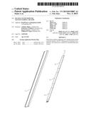
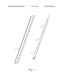
[0011] FIG. 1 shows an exploded view of a heater rod.
DESCRIPTION
[0012] The embodiments described below are not intended to be exhaustive or to limit the invention to the precise forms disclosed in the following description. Rather, the embodiments are chosen and described so that others skilled in the art may appreciate and understand the principles and practices of this disclosure.
[0013] The heater rod comprises a flat tube 1 made of metal, e.g., aluminum, and one or several PTC heating resistors 2 arranged inside the tube 1. The heating resistor 2 is provided as one or several layers that is/are screen printed onto a substrate 3.
[0014] The substrate 3 can be a strip of sheet metal, e.g., aluminum. The PTC heating resistor 2 can be screen printed onto a front side of a sheet metal strip. The sheet metal strip can be electrically insulated from the metallic tube 1 by an electrically insulating layer, e.g., a strip of electrically insulating ceramic like alumina or a polymer film. Instead of a separate insulating layer, like an additional strip or film, the insulating layer may also be part of the metal strip, e.g., an anodized surface.
[0015] Another possibility is to use a ceramic strip as a substrate. For example the PTC heating resistor 2 can be screen printed onto a strip of electrically insulating ceramic like alumina. If the substrate is a strip of electrically insulating ceramic, the substrate may be prepared by depositing an electrically conducting layer, e.g., a metallic layer, onto the strip of electrically insulating ceramic. The PTC heating resistor is then printed onto the electrically conducting layer. The electrically conducting layer may be deposited by printing conductor paste onto one side of the ceramic strip. Another possibility is to use chemical or physical deposition methods, e.g., vapor deposition, for depositing a metallic layer onto one side of the ceramic strip.
[0016] After the substrate 3 and the at least one PTC heating resistor 2 are placed inside the flat tube 1, tube 1 is compressed. Thereby the tube 1 is made even flatter by plastic deformation. Thermal contact between the PTC heating resistor 2 and the metal tube 1 is improved by compression. The flat tube 1 is a profile tube which can be produced by extrusion. The flat tube 1 preferably has generally rectangular interior.
[0017] The PTC heating resistor 2 is based on barium titanate. Some of the barium and or titanium atoms of the PTC heating resistor 2 may be substituted by calcium, strontium and/or lead for example. For example, the metal atoms of the sintered PTC heating resistor 2 may comprise 30 to 40% Ba, 50 to 60% Ti, up to 10% Pb, and 0.5 to 5% other metal atoms. These percentages are atomic percentages of metal atoms present in the PTC heating resistor, i.e. neglecting the oxygen atoms. The screen printing is done with a paste or ink. After the printing process the substrate is fired. Additional PTC heating layers can be printed on top of each other. Thereby the heating rod can be produced with a desired heating power and/or precisely defined resistance levels.
[0018] While exemplary embodiments have been disclosed hereinabove, the present invention is not limited to the disclosed embodiments. Instead, this application is intended to cover any variations, uses, or adaptations of this disclosure using its general principles. Further, this application is intended to cover such departures from the present disclosure as come within known or customary practice in the art to which this invention pertains and which fall within the limits of the appended claims.
User Contributions:
Comment about this patent or add new information about this topic:
Images included with this patent application:
 |  |
| New patent applications in this class: | |
| Date | Title |
|---|---|
| 2019-05-16 | Electric heater crushable cores and compacted unitary heater devices and method for making such devices |
| 2016-03-17 | Modular heater and associated parts |
| 2016-02-18 | Electric heater and method for manufacturing electric heater |
| 2015-10-15 | Electric heater |
| 2015-10-15 | Glow plug |
| New patent applications from these inventors: | |
| Date | Title |
|---|---|
| 2015-05-14 | Temperature sensor |
| Top Inventors for class "Electric heating" | |
| Rank | Inventor's name |
|---|---|
| 1 | Steven R. Peters |
| 2 | Shou-Shan Fan |
| 3 | Chen Feng |
| 4 | Kai-Li Jiang |
| 5 | Chang-Hong Liu |