Patent application title: SYSTEM FOR ACQUIRING TARGETS AND AUTOMATICALLY CORRECTING THE FIRING OF SMALL ARMS
Inventors:
Ian Alan Marr (La Habra, CA, US)
IPC8 Class: AF41A2128FI
USPC Class:
42 84
Class name: Firearms electric appliances
Publication date: 2015-10-29
Patent application number: 20150308771
Abstract:
A system to acquire, via sensor data, and correct the trajectory of a
fired bullet before it leaves the fire arm by directing the bullet
exhaust gases via actuated gas ports, located on and in the compensator,
to the corrected orientation as determined by the sensor data.
Furthermore sensor data is additionally taken after the firing of the
bullet to update future corrections. This system would be attached or
wholly integrated into conventional small arms to create a quick target
acquisition and firing correction system for the fire arm operator.Claims:
1. An apparatus comprising: An operable gas port compensator connected to
a human visual interface, sensor package and processing unit, to be
utilized as a small arms target acquiring and correction system.
2. The apparatus of claim 1, wherein the human visual interface system is detached from the fire arm allowing for remote interface.
3. The apparatus of claim 1, further comprising of the gas port actuators located at the gas exhaust port of the fire arm, should the main gas exhaust be located other than the barrel end.
Description:
SUMMARY OF INVENTION
[0001] The present invention allows for the rapid acquisition of targets and the means to more accurately hit those targets with small arms. This invention consists of human visual interface, trigger sensor, a sensor package, a processing unit and a compensator with gas port actuators.
INVENTION BACKGROUND
[0002] Small arms sights have existed as variations of fixed, adjustable and optical since their inception. Virtually every type of sighting device or aid possible has been utilized, but devices to correct the physical fire arm has been largely unsuccessful. Larger, non-handheld, guns that do have fire corrective systems utilize systems that stabilize and reduce recoil forces. In order to utilize these same techniques on small arms would be to increase the size and bulk of the fire arms to a point of impracticality for field use. This would also imply that the fire arm operator, user, was capable of correctly positioning the fire arm to be able to hit the intended target.
[0003] Due to advances in processor speeds and the speeds of actuating devices we have come to a point where target identification, target displacement from the current aim and actuation of the gas ports can all occur from the time the bullet ignites to the time it enters the compensator. Basically, the same forces which pull the shooter off target are being redirected to push the shooter on target.
[0004] A typical time for a bullet to leave the barrel of an M-16/AR-15 rifle with a 16'' barrel is about 1400 micro seconds (5.56 mm/0.223 is the fastest commonly used ammunition at the time of this application). Allowing for post fire processing for future corrections brings the total time to between 1600 to 2000 micro seconds. When compared to the highest rated automatic fire rate for the M-16/AR-15 of 950 rounds per minute comes to 63,158 micro seconds per round; this system would be wholly suitable for fully automatic weapons target acquisition & correction. In other words each round fired under fully automatic fire would be individually corrected for trajectory, and become increasingly accurate due to post fire processing corrections.
[0005] Currently, large aperture sights such as reflex or holographic sights have roughly 0.835'' from side to side of the sight lens. This translates into 3.98 degrees of rotation (239 MOA) to sight on anything within the sight when the operator's eye is 6'' from the lens. In most cases this requires about 11/2'' of barrel movement to center the barrel on any target within the sight.
[0006] Due to the small changes necessary to place the barrel on or off the intended target many designers and manufacturers have created compensators that evenly distribute the exhaust gases evenly around the barrel and, with repeating rifles, a portion of these gases are used to reset the firing mechanism.
BRIEF DESCRIPTIONS OF DRAWING
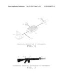
[0007] FIG. 1 is the graphical description of the invention components, and their connections to each other. 01 The Human Visual Interface is a device that allows for the human portion of the targeting process via a recital-like sighting/targeting environment. 02 The Trigger Sensor is an electronic or mechanical system that starts the target processing function when the firearm trigger is depressed sufficiently to release the firearm's hammer. 03 The Processor Unit is the combination of electronics used to identify potential targets from the Sensor Package (04), calculate the target correction and signal the Gas Port Actuators (06). 05 The Compensator is a compensator that houses the Gas Port Actuators (06), and applies the corrective force to the bullet in motion. 06 The Gas Port Actuators are spring loaded slides that cover the exhaust gas port located in the compensator (05) which are operated via quick action motive device such as an actuator or servo.
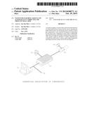
[0008] FIG. 2 is a contextual graphical description of the major components of the invention which display their relation physically to each other and a typical firearm. The Trigger Sensor (02) is not shown as it would not be readily visible from the exterior of the firearm. 07 This is an example of a firearm which might have the invention mounted upon it for use. 08 The Human Visual Interface would be mounted in a typical fashion as sight or rear portion of an iron sight system for ease of use in the human portion of the targeting process. 09 The Processor Unit housing contains the electronics and battery components necessary for the unit's operation. Final size and configuration would be variable the system requires. 10 The Sensor Package would be located near the front of the firearm such as the location of the front of an iron sight system with an unobstructed view in front of the firearm's barrel. 11 The Compensator would be located on the end of the barrel, typically by screw thread.
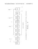
[0009] FIG. 3 is a diagrammatic representation of the functional process that occurs from the time the trigger is actuated, until the system is ready to fire another bullet. The individual steps are additionally described in the detailed description of the invention. 12 The process is described in micro seconds which are 1/1,000,000 of a second long, additionally is shown are the maximum number of seconds that have passed in order for the system to be effective with modern ammunition. 13 The Human Action steps are those which occur prior to the start of the invention's actions. Typically this would be rough targeting and the depressing of trigger before the activation of the hammer. 14 The Mechanical Action is the point, if any, that occurs between the point at which the hammer is triggered and the Trigger Sensor (02) is tripped. To an extended point it also covers the action between when the hammer is triggered and the bullet starts to move due to the primer and propellant ignition. 15 The Target Processing refers to the gathering of the sensor data, identifying potential targets, locating the target, and applying modifying data to the targeting data. 16 Actuator Processing is where the modified targeting data is converted into actuator powering, and sent to the gas port actuators. 17 The Gas Port Actuators move the gas port slides/covers into place to provide exhaust gas exhaust ports. This step must start no later than 600 micro seconds after the bullet starts accelerating in order for the actuators to have time to move the gas port slides/covers into place. 18 Trajectory Change occurs as the bullet passes the gas exhaust ports and is within the compensator throat. As the exhaust gasses exit the ports the barrel of the firearm is forced in the opposite direction dragging the moving bullet along the same path as long as it is still within the compensator throat. 19 The Bullet Leaves the barrel/compensator at or shortly after 1400 micro seconds, and is no longer correctible by the proposed system. 20 Post Fire Processing is where the process again captures the sensor data and locates the target, but this time instead of applying the corrective data to the location data it writes the amount of correction the corrective data accomplished, allowing for better corrective data for the next firing. 21 Ready to Fire occurs after the corrective data has been written to the corrective data tables, and the system is ready for the next Trigger Sensor (02) activation.
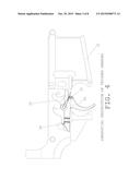
[0010] FIG. 4 is a graphical and contextual description of the Trigger Sensor. 22 The Receiver (lower receiver in the displayed case) houses the trigger assembly. 23 The trigger is used to displace the hammer assembly, and to start the hammer assembly in motion. 24 The hammer assembly (only the disconnector is shown for clarity) which is used strike the primer hard enough to ignite the primer and propellant of the bullet. 25 The trigger spring which used as the counteractive force of the trigger. 26 The Trigger Sensor (02) which is placed such that it will be tripped once the trigger is depressed far enough to release the hammer assembly (24).
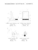
[0011] FIG. 5 is a side elevation of the Human Visual Interface (08). 27 The lens support frame and lens shade. 28 The Human Visual Interface housing for adjustment screws or projection equipment if a holographic or video projection is used. 29 Rail mounting structure (i.e. tactical or Weaver rails). 30 Adjustment screws to alter the height/tilt of the Human Visual Interface.
[0012] FIG. 6 is a front (interface side) of the Human Visual Interface (08). 31 The lens support frame and lens shade (27). 32 The Human Visual Interface lens. 33 The correctible reticle. This is the estimated correctible range of the invention projected onto the Human Visual Interface lens. 34 The reticle. This is the projected representation of what the barrel is pointed towards. 35 The Human Visual Interface housing (28). 36 The rail mounting structure (29). 37 The Human Visual Interface adjustment screws (30).
[0013] FIG. 7 is a side elevation of the Sensor Package (10). 38 The firearm, as a typical representation. 39 The firearm barrel to which the Sensor Package would most likely be attached. 40 The Sensor Package frame and shade. 41 The Sensor Package housing for the adjustment screws and sensor electronics. 42 Adjustment screws to alter the height/tilt of the Sensor Package. 43 The barrel bracket to provide a firm base for the Sensor Package housing. 44 Barrel strap. 45 Barrel strap fasteners.
[0014] FIG. 8 is the front elevation of the Sensor Package. 46 The Sensor Package frame and shade (40). 47 The sensor shroud. 48 The sensor(s) lens or collection apparatus(es). 49 The Sensor Package housing (41). 50 Adjustment screws (42). 51 Barrel strap (44). 52 The firearm barrel (39). 53 Barrel strap fasteners (45).
[0015] FIG. 9 is a cross section view of the barrel with compensator assembly (11). 54 The compensator throat which is used to change the trajectory of the moving bullet. 55 The gas port slide/cover end support pocket. 56 The exhaust gas port which is used to push the end of the firearm bare to the corrected position. 57 The exhaust gas port (56) beyond. 58 The gas port slide/cover pocket cover. 59 The gas port slide/cover which is used to direct the exhaust gasses. 60 The gas port slide/cover shaft. If used with an actuator, as shown, it would be composed of or lined with ferrous material. 61 The barrel-compensator screw threads to attach the compensator to the end of the barrel. 62 The actuator-return quarter turn screw thread to attach the actuator-return housing to the compensator. 63 The gas port actuator or servo mechanism, an actuator ring is shown. 64 The gas port slide/cover stop to prevent the slide/cover from moving any further. 65 Pressure equalizing port to allow free air movement in the slide/cover return chamber, and preventing pressure build-ups. 66 A wire guide for the gas port actuators (63). 67 The gas port actuator return spring. 68 The firearm barrel.
[0016] FIG. 10 is a side elevation of the barrel with compensator assembly (11). 69 The compensator throat (54). 70 The outer gas port ring. 71 The gas port slide/cover, in the closed position (59). 72 The gas port actuator (63) support ring. This is also where the quarter turn screw threads are located. 73 The actuator-return body. 74 Pressure equalizing port (65). 75 The firearm barrel.
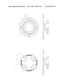
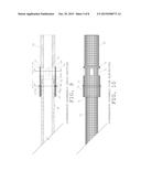
[0017] FIG. 11 is a cross sectional view of the compensator assembly located at the gas exhaust ports. 76 The barrel aperture. 77 The exhaust gas port. 78 The gas port slide/cover (59). 79 The compensator body. 80 quarter turn pocket for the gas port slides/covers.
[0018] FIG. 12 is a cross sectional view of the compensator assembly located at the actuator support ring. 81 The firearm barrel. 82 The gas port actuator support ring. 83 The actuator-return quarter turn screw thread ring to attach the actuator-return housing to the compensator. 84 The gas port actuator or servo mechanism (63). 85 The gas port slide/cover actuator shaft.
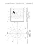
[0019] FIG. 13 is a graphical depiction of the correctible range of the compensator assembly described in minutes of arc (MOA), also the imposed correctible range used on the Human Visual Interface (08). 86 This is the theoretical center at which the barrel is pointing. 87 The angle of elevation in degrees with negative values expressed in brackets. 88 The correctible range imposed on the graph. 89 The vertical centerline. 90 The concentric step guide in MOA. 91 The horizontal centerline.
[0020] FIG. 14 is a graphical representation of the sensor data field and basic processor calculations. 92 Data field range. 93 Data point as a matrix. 94 Data center point. This point should be aligned with the barrel sight. 95 The correctible data range. Data outside of this range is ignored by the first targeting process, but included in the correction phase. 96 Valid data points/range. 97 The total number of data point in vertical range of the valid data blob. 98 The vertical range is halved to establish the center of the vertical range. 99 The total number of data point in horizontal range of the valid data blob. 100 The horizontal range is halved to establish the center of the horizontal range. 101 The center vertical range is used to establish the vertical range from the center of the barrel position. This data is compared to the data table to create corrective actuator data, and adjust the barrel vertically. 102 The center horizontal range is used to establish the horizontal range from the center of the barrel position. This data is compared to the data table to create corrective actuator data, and adjust the barrel horizontally.
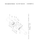
[0021] FIG. 15 is an exploded 3D view of the compensator and component parts. 103 The compensator. 104 Gas ports. 105 Gas port slide/cover. 106 Gas port slide/cover shaft. 107 Actuator ring. 108 Return spring. 109 Actuator-return body. 110 Pressure equalizer port. 111 Firearm barrel.
DETAILED DESCRIPTION OF THE INVENTION
[0022] The major components of this invention consists of human visual interface, trigger sensor, a sensor package, a processing unit and a compensator with gas port actuators.
[0023] A human visual interface is defined as sight, monitor or eye piece capable of showing at what the fire arm is pointing. In addition a superimposed shape or outline would be shown within the sight to show the correctable movement of the fire arm. In other words an area in which the corrective abilities of the fire arm could adjust within.
[0024] A trigger sensor is defined as a device that can signal the processing unit when the trigger has been pulled enough to release the hammer.
[0025] A sensor package is defined by a device or series of devices that serve as the supply of external input data for the processing unit. Input data would be required to provide quantifiable data points across a field of area as a matrix of data points. Any sensor packages would be positioned such that the center of the data field or matrix would also be the center of the human visual interface. Examples of a sensor package would be a visual spectrum or infrared cmos sensor, range finder, reflected cast fluorescence or other data collecting device.
[0026] A processing unit is defined as a microprocessor or set of microprocessors that collects the sensor data, processes the data to establish target data, vectorize the difference between the target and the center, calculate the vectors based upon the gun data table and send the servo to actuator signals to the compensator gas port actuators.
[0027] A compensator with gas port actuators is defined as a fire arm barrel end attachment and/or an end attachment to the exhaust gas port, if the gas exhaust port is other than the barrel, that has operable ports along the attachment which allow the end of the gun to transverse side to side, up and down by venting the bullet exhaust gases thus providing barrel movement which is the corrective factor of the system. The operable ports would be operated by a servo, actuator or other operable part to provide the control of the exhaust gases.
[0028] The system operates thusly:
[0029] 1. The shooter places the target within the target field shown on the human visual interface.
[0030] 2. The shooter pulls the trigger to actuation of the hammer.
[0031] 3. The trigger sensor reports to the processor to capture the current sensor data.
[0032] 4. The bullet ignites and starts accelerating to the end of the barrel.
[0033] 5. The processor searches for data within DATA TABLE 1 defined ranges starting from the center of the data matrix (location of barrel).
[0034] 6. The processor locates the first sensor data that qualifies that is closest to the center of the data matrix.
[0035] 7. The processor defines the mean x and y to define the center of the located data, by location steps in the data matrix.
[0036] 8. The processor defines x and y coordinates in location steps in the data matrix.
[0037] 9. The processor applies values from DATA TABLE 2 to the x and y coordinates.
[0038] 10. The processor converts the adjusted x and y coordinates into actuator movement data.
[0039] 11. The actuators move the gas port slides.
[0040] 12. The bullet enters the barrel compensator.
[0041] 13. As the bullet passes the gas ports, the exhaust gases vent through the open ports.
[0042] 14. The end of the barrel is forced towards a corrected direction by the exhausting gases.
[0043] 15. The bullet leaves the compensator along the corrected trajectory.
[0044] 16. The processor starts steps 5-9.
[0045] 17. The processor notes the difference between the original step 8 and the new step 8, and applies the new data to DATA TABLE 2.
[0046] DATA TABLE 1 comprises of target acceptable data ranges. For example if using infrared data the data table would list actionable values.
[0047] DATA TABLE 2 comprises of information about the bullet, the fire arm and correction values resulting in the difference between ideal correction and actual or achieved correction.
User Contributions:
Comment about this patent or add new information about this topic:
Images included with this patent application:
 |  |
 |  |
 |  |
 |  |
 |
| Similar patent applications: | |
| Date | Title |
|---|---|
| 2016-04-14 | Method of using a touch display screen to adjust and determine a reticle of electronic firearm sight |
| 2016-01-14 | Systems and methods associated with a firearm sleeve |
| 2016-04-21 | System and method of controlling discharge of a firearm |
| 2016-03-10 | Automatic adjustable buttstock for small arms |
| 2016-01-21 | Trigger group for semi-automatic firearms |
| New patent applications in this class: | |
| Date | Title |
|---|---|
| 2014-12-25 | Accessory mount for a firearm |
| 2014-12-11 | Powered tactical rail (aka picatinny rail) system and method of using the same |
| 2014-10-30 | Selectable kinetic energy of projectiles |
| 2014-09-04 | System, apparatus and circuits for tactical rail accessory management |
| 2014-08-07 | Evidence collecting and recording apparatus for a gun |
| Top Inventors for class "Firearms" | |
| Rank | Inventor's name |
|---|---|
| 1 | Michael T. Mayberry |
| 2 | Mark C. Laney |
| 3 | Stephen P. Troy |
| 4 | Russell A. Potterfield |
| 5 | Dennis Cauley |