Patent application title: Frame for Mounting an Enclosure
Inventors:
Chris Mercieca (New South Wales, AU)
Nyein Aung (New South Wales, AU)
IPC8 Class: AE04H1548FI
USPC Class:
135139
Class name: Portable shelter (i.e., tent or canopy) framework telescoping and foldable
Publication date: 2015-10-29
Patent application number: 20150308146
Abstract:
A frame for mounting an enclosure. The frame having a first sub-frame and
a second sub-frame. Each said sub-frame having a pair of elongate side
members connected by an elongate cross member. A hinge member locatable
at each free end of the side members of the sub-frames and adapted to
permit movement of the sub-frames with respect to each other. A foot is
extendible from each hinge member and adapted to be placed on a surface.
A support member is adapted to connect the feet to the sub-frames to
provide stability to the frame. The frame having no base support located
on a side opposite to where an enclosure door will be located in use.Claims:
1. A frame for mounting an enclosure; the frame having: a first sub-frame
and a second sub-frame; each said sub-frame having a pair of elongate
side members connected by an elongate cross member; a hinge member
locatable at each free end of said side members of said sub-frames
adapted to permit movement of said sub-frames with respect to each other;
a foot extendible from each said hinge member and adapted to be placed on
a surface; a support member adapted to connect said feet to said
sub-frames to provide stability to said frame, and wherein said frame has
no base support located on a side opposite to where a door will be
located in use contacting a ground surface.
2. The frame according to claim 1, wherein said frame is for external mounting of a portable enclosure.
3. The frame according to claim 1, wherein said enclosure is a tent.
4. The frame according to claim 1, wherein said sub-frames are n-shaped.
5. The frame according to claim 1, wherein said side members are telescopically extendable members.
6. The frame according to claim 1, wherein said cross members are telescopically extendable members.
7. The frame according to claim 1, wherein said feet do not extend longitudinally the length of said respective side members in use.
8. The frame according to claim 1, wherein said side members and feet are operatively associated with each other so that in a closed configuration each are substantially parallel to each other and in an opened configuration each are substantially spaced apart radially from said hinge.
9. The frame according to claim 1, wherein in an opened configuration said frame is adapted to hold a tent cover fixed to said frame by fasteners.
10. The frame according to claim 1, wherein said cross member is adapted to fold into a first portion and a second portion so that each portion is substantially parallel to each other when the frame is in the closed configuration.
11. The frame according to claim 1, wherein said side members and cross member are connected by a hinge adapted to permit said side members and cross members in the opened configuration to be placed at right angles to each other and in the closed configuration to be locatable substantially parallel to each other.
12. The frame according to claim 1, whereby in use the frame is modular being adapted to connect to other frames on each side to extend a useable surface area.
Description:
FIELD OF THE INVENTION
[0001] The present invention relates to a frame for mounting an enclosure and in particular a frame for mounting a tent, where the frame has no rear base support contacting a ground surface.
BACKGROUND OF THE INVENTION
[0002] Enclosures are used throughout the world to protect people and goods from the elements, animals or other people. Most enclosures are fixed structures such as buildings, sheds, or the like. There is however a need for portable enclosures for temporary use. For example, portable enclosures are commonly used during music, sporting and other social events. Portable enclosures have also been used in places such as sporting fields and beaches to inhibit sun exposure. Portable enclosures are also commonly used in the form of tents or the like during camping, hiking or on expeditions.
[0003] A major disadvantage with existing portable enclosures like a tent is that they are not sufficiently compact and require a significant number of elements and time to erect. This is typically due to the frame structure used and in particular the rear base support. Though smaller enclosures exist, such as swags or the like, those smaller enclosures are not sufficient in size for most use or for multiple people. Further, most frames are limited to fit with only a simple cover limiting in use.
[0004] The problem with a swag for example is that when a swag design is enlarged it is very clumsy and difficult for one person to lay down a cover or enclosure of the same volume, insert a strong enough and yet flexible enough pole structure, whilst holding it up as a user secures everything. Most swags have a single rigid beam or rib from which the entire tent hangs, resulting in a lot of sagged areas, especially at a similar size, scale, and volume. In fact, a swag is not scalable to a similar size and volume as a conventional tent, without serious modifications. The reason being is that the weight of the canvas will increase exponentially. There is a need for a good portion of the living area to be taunt offering a superior profile for weather protection and airflow. Most swags, due to the single pole design, that is restrained by fabric, will also not allow for the addition of accessories. There is a need for a frame and tent that offer an extended section from the back and/or sides in addition, due to its frame structure, can potentially allow for multiple optional accessories such as side and front panels, allow leech structures such as Tagalong Tents or the like.
[0005] Accordingly, there is a need for a frame that can be used for mounting various types of enclosures in a quick, easy way and where the frame is compact in travel.
OBJECT OF INVENTION
[0006] It is an object of the present invention to substantially overcome or at least ameliorate one or more of the disadvantages of the prior art, or to at least provide a useful alternative.
SUMMARY OF INVENTION
[0007] There is disclosed herein a frame for mounting an enclosure; the frame having:
[0008] a first sub-frame and a second sub-frame;
[0009] each said sub-frame having a pair of elongate side members connected by an elongate cross member;
[0010] a hinge member locatable at each free end of said side members of said sub-frames adapted to permit movement of said sub-frames with respect to each other;
[0011] a foot extendible from each said hinge member and adapted to be placed on a surface;
[0012] a support member adapted to connect said feet to said sub-frames to provide stability to said frame, and wherein said frame has no base support located on a side opposite to where a door will be located in use contacting a ground surface.
[0013] Preferably, said frame is for external mounting of a portable enclosure.
[0014] Preferably, said enclosure is a tent.
[0015] Preferably, said sub-frames are n-shaped.
[0016] Preferably, said side members are telescopically extendable members.
[0017] Preferably, said cross members are telescopically extendable members.
[0018] Preferably, said feet do not extend longitudinally the length of said respective side members in use.
[0019] Preferably, said side members and feet are operatively associated with each other so that in a closed configuration each are substantially parallel to each other and in an opened configuration each are substantially spaced apart radially from said hinge.
[0020] Preferably, in an opened configuration said frame is adapted to hold a tent cover fixed to said frame by fasteners.
[0021] Preferably, said cross member is adapted to fold into a first portion and a second portion so that each portion is substantially parallel to each other when the frame is in the closed configuration.
[0022] Preferably, said side members and cross member are connected by a hinge adapted to permit said side members and cross members in the opened configuration to be placed at right angles to each other and in the closed configuration to be locatable substantially parallel to each other.
[0023] Preferably, in use the frame is modular being adapted to connect to other frames on each side to extend a useable surface area.
BRIEF DESCRIPTION OF DRAWINGS
[0024] A preferred embodiment of the invention will now be described, by way of example only, with reference to the accompanying drawings, wherein:
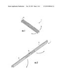
[0025] FIG. 1 shows an embodiment of the present invention in the closed configuration;
[0026] FIG. 2 shows FIG. 1 being expanded;
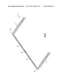
[0027] FIG. 3 shows FIG. 2 being expanded;
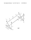
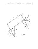
[0028] FIG. 4 shows FIG. 3 being expanded;
[0029] FIG. 5 shows FIG. 4 being expanded;
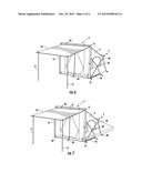
[0030] FIG. 6 is a first perspective view of an embodiment of the present invention;
[0031] FIG. 7 is a second perspective view of a second embodiment of the present invention; and
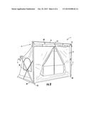
[0032] FIG. 8 is a third perspective view of a third embodiment of the present invention.
DESCRIPTION OF EMBODIMENTS
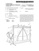
[0033] There is disclosed herein a frame 1 for mounting a portable enclosure 2. In a preferred form, the frame 1 would be external of the enclosure 2 as best seen in FIG. 3 where the enclosure 2 is a tent or the like. It should however be understood that other enclosures could be utilised. The frame 1 includes a first sub-frame 4 and a second sub-frame 5 however could include any number of sub-frames 4, 5. Each sub-frame 4, 5 has a pair of side members 7 connected by a cross member 8. In use, the side members 7 and cross members 8 form a generally n-shape as best seen in FIG. 5. The side members 7 are preferably telescopically extendable so that their longitudinal length can be varied by a user (see FIG. 4). A locking means 10 could be utilised to lock the telescopically side members 7 at a particular length. The side members 7 could however come in multiple folding parts. The cross members 8 could also be telescopically extendable or include a hinge 12 to permit portions of the cross member 8 to fold towards each other to be substantially parallel when the frame 1 is in the closed configuration (see FIGS. 1 and 2). The members 7, 8 can include slide mechanism, twist and lock, snap locks, press button locks or the like. The cross members 8 and side members 7 are connected together by hinges 15. The hinge 15 permits the side members 7 and cross members 8 to form a substantially right angle in the open configuration as shown in FIGS. 2 and 3 and in the closed configuration to be substantially parallel to each other (see FIG. 1). The frame 1 further includes a pair of feet 20 adapted to be located on a surface upon which the frame 1 is to be mounted. The feet 20 extend from a base hinge 25. The base hinge 25 locates the free ends of each of the side members 7 of the sub-frames 4 and 5. The base hinge 25 permits the side members 7 and feet 20 to rotate about the base hinge 25 and move apart from each other so that in the closed configuration each of the side members 7 and feet 20 are located substantially parallel to each other (see FIG. 1) and in the opened configuration each of the side members 7 and feet 20 are radially spaced apart (see FIG. 5). As shown in the drawings by an acute angle. They could however be spaced apart by any suitable angle. The feet 20 do not extend away from the base hinge 25 for a longitudinal distance greater than that of the respective side members 7. That is, the feet 20 would never be longer than the travel pack size. In effect, the frame 1 has no rear base support contacting the ground surface. That is, the location opposite where the front of the tent will be located. The frame 1 further includes at least one support member 30 adapted to connect the feet 20 to at least one of the first and second sub-frames 4, 5 or both sub-frames 4, 5 as shown in the figures. Support members 30 provide additional stability to the frame 1. The support members 30 can be removably attachable to the feet 20 and side members 7, fixedly connected thereto or slidably connected, press button, twist lock or the like. Alternatively, the support member 30 can be clicked or snapped onto the side members 7 and feet 20 by way of clips 40 or the like. The frame 1 could further include numerous mounts 60 for the securing of pegs, lines or the like to provide further stability. The frame 1 could be any size due to the ability of each of the members 7, 8, 20, 30 to fold with respect to each other or be telescopic. See for example in FIG. 1 how compact the frame 1 becomes. The frame 1 could mount any type of enclosure 2 either with the frame 1 being external of the enclosure 2 as shown with the tent in the figures or could be internal of the enclosure 2.
[0034] In the embodiment in FIGS. 6 to 8, the enclosure 2 further includes an annex 50 extending from the enclosure 2 and hanging from the frame 1 by fastening means 60 and being held at an extended position by poles 51. It should be noted that the feet 20 do not extend all the way to the rear of the enclosure 2. This advantageously keeps the tent compact and allows the tent to fold down to a much smaller package. There is also no need for a full bottom frame and cross bar at the rear base advantageously reducing pack size. Accordingly, the enclosure size is not limited and the inner enclosure dimensions can be limitless. Any number of side, front or back annexes could be added.
[0035] Although the invention has been described with reference to specific examples, it will be appreciated by those skilled in the art that the invention may be embodied in many other forms.
User Contributions:
Comment about this patent or add new information about this topic:
Images included with this patent application:
 |  |
 |  |
 |  |
 |
| Similar patent applications: | |
| Date | Title |
|---|---|
| 2015-10-15 | Expandable hard-shell tent mounted on a roof of vehicle |
| 2015-10-29 | Foldable protection enclosure |
| 2015-10-29 | Bungalow capable of being easily installed and disassembled |
| 2014-06-12 | Hammock enclosure |
| 2015-10-29 | Extendible height container and shelter |
| New patent applications in this class: | |
| Date | Title |
|---|---|
| 2016-06-09 | Awning mounting rack, the awning and an awning top of the awning mounting rack |
| 2016-04-14 | Foldable tent |
| 2016-01-07 | Collapsible gazebo frame with single activation feature |
| 2015-10-22 | Portable folding awning |
| Top Inventors for class "Tent, canopy, umbrella, or cane" | |
| Rank | Inventor's name |
|---|---|
| 1 | Oliver Joen-An Ma |
| 2 | Mark C. Carter |
| 3 | Wanda Ying Li |
| 4 | Wanda Ying Li |
| 5 | Kendyl A. Roman |