Patent application title: Air-Sealed Storage System
Inventors:
Tina Paoli (Scaramento, CA, US)
IPC8 Class: AB65D8120FI
USPC Class:
2065248
Class name: Special receptacle or package evacuated
Publication date: 2015-10-29
Patent application number: 20150307253
Abstract:
An air-sealed storage system prevents metallic items, such as jewelry and
flatware, from tarnishing. The system includes a housing having a bottom
wall and a perimeter wall coupled to and extending upwardly from the
bottom wall. A top edge of the perimeter wall defines an opening into an
interior of the housing. The housing has a port in environmental
communication with the interior of the housing. A vacuum assembly is
operationally coupled to the port of the housing to create suction
through the port to remove air from the interior of the housing. A
flexible hose is couplable to the housing in environmental communication
with the port such that the vacuum assembly provides suction through the
flexible hose. A cover is coupled to the housing and is positionable to
cover the opening into the interior of the housing.Claims:
1. An air-sealed storage system comprising: a housing having a bottom
wall and a perimeter wall coupled to and extending upwardly from said
bottom wall, a top edge of said perimeter wall defining an opening into
an interior of said housing, said housing having a port in environmental
communication with said interior of said housing; a vacuum assembly
operationally coupled to said port of said housing to create suction
through said port into said interior of said housing; a flexible hose
couplable to said housing in environmental communication with said port
such that said vacuum assembly provides suction through said flexible
hose; and a cover coupled to said housing and being positionable to cover
said opening into said interior of said housing.
2. The system of claim 1, further comprising wherein said cover includes a top wall and a peripheral wall coupled to and extending downwardly from said top wall.
3. The system of claim 1, further comprising said cover being pivotally coupled to said housing.
4. The system of claim of claim 2, further comprising said top wall of said cover comprising a transparent panel that permits viewing into said interior of said housing through said transparent panel.
5. The system of claim 1, further comprising a seal coupled to said top edge of said perimeter wall wherein said seal prevents fluid communication between said interior of said housing and an external environment relative to said interior of said housing when said cover is positioned to cover said opening.
6. The system of claim 1, further comprising a connector fluidly coupled to said port, a first end of said flexible hose being couplable to said connector.
7. The system of claim 1, further comprising a locking mechanism coupled to said housing and said cover, said locking mechanism selectively engaging said cover to secure said cover to said housing.
8. The system of claim 1, further comprising a plurality of foot pads coupled to said bottom wall of said housing, said foot pads each being comprised of a non-slip material.
9. The system of claim 1, further comprising a plurality of interior walls each coupled to said housing, said interior walls each extending upwardly from said bottom wall through said interior of said housing defining a plurality of compartments positioned within said interior of said housing.
10. The system of claim 1, further comprising a power source coupled to said vacuum assembly, said power source being electrically coupled to said vacuum assembly.
11. The system of claim 9, further comprising each of said compartments having an interior surface, an entirety of each said interior surface being inset relative to said top edge of said perimeter wall.
12. The system of claim 6, further comprising a one-way valve positioned in said connector for permitting air to flow only in a first direction outwardly from said interior of said housing through said port, a spring being coupled to said one-way valve.
13. An air-sealed storage system comprising: a housing having a bottom wall and a perimeter wall coupled to and extending upwardly from said bottom wall, a top edge of said perimeter wall defining an opening into an interior of said housing, said housing having a port in environmental communication with said interior of said housing; a plurality of interior walls each coupled to said housing, said interior walls each extending upwardly from said bottom wall through said interior of said housing defining a plurality of compartments positioned within said interior of said housing, each of said compartments having an interior surface, an entirety of each said interior surface being inset relative to said top edge of said perimeter wall; a plurality of foot pads coupled to said bottom wall of said housing, said foot pads each being comprised of a non-slip material; a vacuum assembly operationally coupled to said port of said housing to create suction through said port into said interior of said housing; a power source coupled to said vacuum assembly, said power source being electrically coupled to said vacuum assembly; a flexible hose couplable to said housing in environmental communication with said port such that said vacuum assembly provides suction through said flexible hose; a connector fluidly coupled to said port, a first end of said flexible hose being couplable to said connector; a one-way valve positioned in said connector for permitting air to flow only in a first direction outwardly from said interior of said housing through said port, a spring being coupled to said one-way valve; a cover coupled to said housing and being positionable to cover said opening into said interior of said housing, said cover including a top wall and a peripheral wall coupled to and extending downwardly from said top wall, said cover being pivotally coupled to said housing, said top wall of said cover comprising a transparent panel that permits viewing into said interior of said housing through said transparent panel; a locking mechanism coupled to said housing and said cover, said locking mechanism selectively engaging said cover to secure said cover to said housing; and a seal coupled to said top edge of said perimeter wall wherein said seal prevents fluid communication between said interior of said housing and an external environment relative to said interior of said housing when said cover is positioned to cover said opening.
Description:
BACKGROUND OF THE DISCLOSURE
Field of the Disclosure
[0001] The disclosure relates to storage systems and more particularly pertains to a new storage system for preventing metallic items, such as jewelry and flatware, from tarnishing.
[0002] SUMMARY OF THE DISCLOSURE
[0003] An embodiment of the disclosure meets the needs presented above by generally comprising a housing having a bottom wall and a perimeter wall coupled to and extending upwardly from the bottom wall. A top edge of the perimeter wall defines an opening into an interior of the housing. The housing has a port in environmental communication with the interior of the housing. A vacuum assembly is operationally coupled to the port of the housing to create suction through the port to remove air from the interior of the housing. A flexible hose is couplable to the housing in environmental communication with the port such that the vacuum assembly provides suction through the flexible hose. A cover is coupled to the housing and is positionable to cover the opening into the interior of the housing.
[0004] There has thus been outlined, rather broadly, the more important features of the disclosure in order that the detailed description thereof that follows may be better understood, and in order that the present contribution to the art may be better appreciated. There are additional features of the disclosure that will be described hereinafter and which will form the subject matter of the claims appended hereto.
[0005] The objects of the disclosure, along with the various features of novelty which characterize the disclosure, are pointed out with particularity in the claims annexed to and forming a part of this disclosure.
BRIEF DESCRIPTION OF THE DRAWINGS
[0006] The disclosure will be better understood and objects other than those set forth above will become apparent when consideration is given to the following detailed description thereof. Such description makes reference to the annexed drawings wherein:
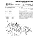
[0007] FIG. 1 is a top front side perspective view of an air-sealed storage system according to an embodiment of the disclosure.
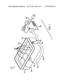
[0008] FIG. 2 is a top front side perspective view of an embodiment of the disclosure showing the cover being open.
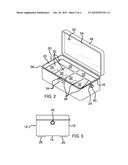
[0009] FIG. 3 is a side view of an embodiment of the disclosure.
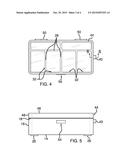
[0010] FIG. 4 is a top view of an embodiment of the disclosure.
[0011] FIG. 5 is a front view of an embodiment of the disclosure.
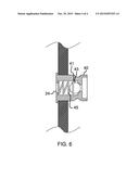
[0012] FIG. 6 is a cross-sectional view of an embodiment of the disclosure taken along line 6-6 of FIG. 4.
DESCRIPTION OF THE PREFERRED EMBODIMENT
[0013] With reference now to the drawings, and in particular to FIGS. 1 through 6 thereof, a new storage system embodying the principles and concepts of an embodiment of the disclosure and generally designated by the reference numeral 10 will be described.
[0014] As best illustrated in FIGS. 1 through 6, the air-sealed storage system 10 generally comprises a housing 12 having a bottom wall 14 and a perimeter wall 16 coupled to and extending upwardly from the bottom wall 14. A top edge 18 of the perimeter wall 16 defines an opening 20 into an interior 22 of the housing 12. The housing 12 has a port 24 in environmental communication with the interior 22 of the housing 12. The housing 12 may be comprised of a rigid material, such as plastic or the like. A plurality of foot pads 26 is coupled to the bottom wall 14 of the housing 12. The foot pads 26 are each comprised of a non-slip material, such as an elastomer or the like.
[0015] A plurality of interior walls 28 is coupled to the housing 12. The interior walls 28 each extend upwardly from the bottom wall 14 through the interior 22 of the housing 12 defining a plurality of compartments 30 positioned within the interior 22 of the housing 12. Each of the compartments 30 has an interior surface 32. An entirety of each interior surface 32 may be inset relative to the top edge 18 of the perimeter wall 16.
[0016] A vacuum assembly 34 is operationally coupled to the port 24 of the housing 12 to create suction through the port 24 to remove air from the interior 22 of the housing 12. A power source 36 is coupled to the vacuum assembly 34. The power source 36 is electrically coupled to the vacuum assembly 34. The power source 36 may comprise a power cord configured for electrically coupling to an external electrical outlet. An actuator 37 may be coupled to the vacuum assembly 34. The actuator 37 is operationally coupled to the power source 36 for actuating the vacuum assembly 34 to create suction through the port 24 in order to remove air from the interior 22 of the housing 12. A flexible hose 38 is couplable to the housing 12 in environmental communication with the port 24 such that the vacuum assembly 34 provides suction through the flexible hose 38.
[0017] A connector 40 is fluidly coupled to the port 24. A first end 42 of the flexible hose 38 is couplable to the connector 40 such that the first end 42 of the hose 38 is in fluid communication with the port 24. A one-way valve 41 may be positioned in the connector 40. The one-way valve 41 may comprise a conventional ball valve 43 having a biasing member 45 coupled thereto. The one-way valve 41 maintains the vacuum within the housing 12 even after the hose 38 is removed from the connector 40 by only allowing air to flow from the interior 22 of the housing 12 outwardly through the port 24 and preventing airflow in the opposite direction.
[0018] A cover 44 is coupled to the housing 12 and is positionable to cover the opening 20 into the interior 22 of the housing 12. The cover 44 may be pivotally coupled to the housing 12 using one or more hinges 50. The cover 44 includes a top wall 46 and may also include a peripheral wall 48 coupled to and extending downwardly from the top wall 46. The top wall 46 of the cover 44 may comprise a transparent panel 52 that permits viewing into the interior 22 of the housing 12 through the transparent panel 52. A locking mechanism 54 of generally conventional design may be coupled to the housing 12 and the cover 44. The locking mechanism 54 selectively engages the cover 44 to secure the cover 44 to the housing 12. A seal 56 is coupled to the top edge 18 of the perimeter wall 16 wherein the seal 56 prevents fluid communication between the interior 22 of the housing 12 and an external environment relative to the interior 22 of the housing 12 when the cover 44 is positioned to cover the opening 20. The seal 56 may comprise a rubber material or any other material sufficient to create an air-tight seal between the cover 44 and the housing 12.
[0019] In use, metallic items, such as silver jewelry, flatware or the like, are positioned within the compartments 30. The cover 44 is positioned onto the housing 12 to cover the opening 20 into the interior 22 of the housing 12. The first end 42 of the hose 38 is coupled to the connector 40. The vacuum assembly 34 is then actuated to create suction through the port 24. The seal 56 further helps to prevent air from flowing into the interior 22 of the housing 12 from the external environment. In this manner, the system 10 helps prevent tarnishing of metallic items positioned within the housing 12 by creating an air-tight housing 12 for storing such items.
[0020] With respect to the above description then, it is to be realized that the optimum dimensional relationships for the parts of an embodiment enabled by the disclosure, to include variations in size, materials, shape, form, function and manner of operation, assembly and use, are deemed readily apparent and obvious to one skilled in the art, and all equivalent relationships to those illustrated in the drawings and described in the specification are intended to be encompassed by an embodiment of the disclosure.
[0021] Therefore, the foregoing is considered as illustrative only of the principles of the disclosure. Further, since numerous modifications and changes will readily occur to those skilled in the art, it is not desired to limit the disclosure to the exact construction and operation shown and described, and accordingly, all suitable modifications and equivalents may be resorted to, falling within the scope of the disclosure. In this patent document, the word "comprising" is used in its non-limiting sense to mean that items following the word are included, but items not specifically mentioned are not excluded. A reference to an element by the indefinite article "a" does not exclude the possibility that more than one of the element is present, unless the context clearly requires that there be only one of the elements.
User Contributions:
Comment about this patent or add new information about this topic:
Images included with this patent application:
 |  |
 |  |
 |
| Similar patent applications: | |
| Date | Title |
|---|---|
| 2015-10-15 | Personal items retrieval system |
| 2015-10-29 | Method for stacking of filled sacks to a pallet-free sack stacking |
| 2015-05-14 | Firearm storage unit |
| 2015-10-22 | Power modulation for ammonia delivery system |
| 2015-10-29 | Electrode pad packaging systems and methods |
| New patent applications in this class: | |
| Date | Title |
|---|---|
| 2015-12-24 | Vacuum storage container |
| 2015-11-19 | Container with reusable vacuum seal lid |
| 2015-01-29 | Vacuum contain, twist and lock cap, and pump |
| 2014-12-04 | Vacuum storage bag with exhaust valve and pressure-sealing zipper |
| 2014-07-10 | Vacuum container, twist and lock cap, bottle locker, fluid collector and auto pump |
| Top Inventors for class "Special receptacle or package" | |
| Rank | Inventor's name |
|---|---|
| 1 | Donald E. Weder |
| 2 | Brett R. Glass |
| 3 | Daniel Lee Bizzell |
| 4 | Andrea Biondi |
| 5 | Nicole E. Glass |