Patent application title: COMBINATION DISH
Inventors:
Jeffrey L. Sheppard (Golden, CO, US)
John K. Sheppard (Tampa, FL, US)
Assignees:
BOWLATE LLC
IPC8 Class: AA47G1902FI
USPC Class:
Class name:
Publication date: 2015-08-20
Patent application number: 20150230636
Abstract:
A dish includes a first platform member. A second platform member is
laterally displaced from the first platform member and is elevated with
respect to the first platform member. The second platform member defines
a hole passing therethrough. A ramp structure is disposed between and is
contiguous with both the first platform member and the second platform
member. A bowl, having a bottom that is at a same elevation as the first
platform member, extends upwardly to the second platform member so as to
open to the hole defined by the second platform member.Claims:
1. A dish, comprising: (a) a first platform member having an outside
peripheral edge; (b) a second platform member that is laterally displaced
from the first platform member and that is elevated with respect to the
first platform member, the second platform member defining a hole passing
therethrough; (c) a ramp structure that is disposed between and is
contiguous with both the first platform member and the second platform
member; and (d) a bowl, having a bottom that is at a same elevation as
the first platform member, extending upwardly to the second platform
member so as to open to the hole defined by the second platform member,
and (e) a lip extending upwardly from the outside peripheral edge of the
first platform member and terminating at the ramp structure.
2. The dish of claim 1, wherein the hole is circular and the bowl has a top that is circular.
3. The dish of claim 1, wherein the hole is polygonal and the bowl has a top that is polygonal.
4. The dish of claim 1, wherein the bowl includes a flattened bottom surface.
5. (canceled)
6. The dish of claim 1, wherein the ramp structure comprises a first portion extending from the first platform member that is hingedly coupled to a second portion extending from second platform member and configured to pivot so that the first platform member is movable between a first position in which the first platform member is disposed at an elevation corresponding to a bottom of the bowl and a second position in which the first platform member is disposed above the hole defined by the second platform member.
7. The dish of claim 1, comprising a material selected from a group of materials consisting of: ceramic, glass, wood, bamboo, plastic, plastic composite, foam, melamine, stainless steel, aluminum, metal, paper, natural fiber composites and combinations thereof
8. The dish of claim 1, wherein a food substance is disposed in at least a portion of the bowl.
9. The dish of claim 1, wherein a food substance is disposed on at least a portion of the first platform member.
10. A dish device, comprising: (a) a first platform member having an outside peripheral edge; (b) a second platform member that is disposed adjacent to the first platform member and that is vertically displaced above the first platform member, the second platform member contiguously coupled to the first platform member by a ramp structure disposed therebetween; and (c) a bowl defined by the second platform member and extending downwardly therefrom; and (d) a lip extending upwardly from the outside peripheral edge and terminating at the ramp structure.
11. (canceled)
12. The dish device of claim 10, wherein the bowl comprises a selected shape from a group of shapes consisting of a hemispherical shape and a polyhedronal shape.
13. The dish device of claim 10, wherein the ramp structure comprises a first portion extending from the first platform member that is hingedly coupled to a second portion extending from second platform member and configured to pivot so that the first platform member is movable between a first position in which the first platform member is disposed at an elevation corresponding to a bottom of the bowl and a second position in which the first platform member is disposed above the hole defined by the second platform member.
14. The dish device of claim 10, comprising a material selected from a group of materials consisting of: ceramic, glass, wood, bamboo, plastic, plastic composite, foam, melamine, stainless steel, aluminum, metal, paper, natural fiber composites and combinations thereof
15. A dish unit, comprising: (a) a first platform member; (b) a second platform member that is laterally displaced from the first platform member and that is elevated with respect to the first platform member, the second platform member defining a hole passing therethrough; (c) a ramp structure disposed between the first platform member and the second platform member, the ramp structure having a first portion that extends from the first platform member and a second portion that extends from the second platform member; (d) a hinge structure that hingedly couples the first portion of the ramp structure to the second portion of the ramp structure; and (e) a bowl, having a bottom that is at a same elevation as the first platform member, extending upwardly to the second platform member so as to open to the hole defined by the second platform member, the bowl having a flattened bottom surface.
16. The dish unit of claim 0, comprising wherein the first platform member is movable between a first position in which the first platform member is disposed at an elevation corresponding to a bottom of the bowl and a second position in which the first platform member is disposed above the hole defined by the second platform member.
17. The dish unit of claim 0, wherein the bowl comprises a selected shape from a group of shapes consisting of a hemispherical shape and a polyhedronal shape.
18. The dish unit of claim 0, further comprising a lip extending upwardly from at least one peripheral edge of the first platform member.
19. The dish unit of claim 0, comprising a material selected from a group of materials consisting of: ceramic, glass, wood, bamboo, plastic, plastic composite, foam, melamine, stainless steel, aluminum, metal, paper, natural fiber composites and combinations thereof
Description:
CROSS-REFERENCE TO RELATED APPLICATION(S)
[0001] This application claims the benefit of U.S. Provisional Patent Application Ser. No. 61/940,156, filed Feb. 14, 2014, the entirety of which is hereby incorporated herein by reference.
BACKGROUND OF THE INVENTION
[0002] 1. Field of the Invention
[0003] The present invention relates to dinnerware and, more specifically, to a dish that includes features of a bowl and a plate.
[0004] 2. Description of the Related Art
[0005] Dishes are dinnerware upon which, or in which, food is placed for consumption. For example, solid food (e.g., sandwiches) is often placed on plates and liquid food (e.g., soup) is often placed in bowls. In the food service environment, use of plates and bowls is common. However, when customers of a food service establishment, such as a restaurant, place orders requiring both plates and bowls (e.g., soup and a sandwich) the delivery of such orders to the customers can be awkward, especially when several customers at the same table place similar orders. Additionally, many restaurants ask their customers to stack their dishes at a dish return location upon departing. Stacking both plates and bowls can be bulky and cumbersome.
[0006] Therefore, there is a need for a dish that is easy to serve and to stack.
SUMMARY OF THE INVENTION
[0007] The disadvantages of the prior art are overcome by the present invention which, in one aspect, is a dish that includes a first platform member. A second platform member is laterally displaced from the first platform member and is elevated with respect to the first platform member. The second platform member defines a hole passing therethrough. A ramp structure is disposed between and is contiguous with both the first platform member and the second platform member. A bowl, having a bottom that is at a same elevation as the first platform member, extends upwardly to the second platform member so as to open to the hole defined by the second platform member.
[0008] In another aspect, the invention is a dish device that includes a first platform member having an outside peripheral edge. A second platform member is disposed adjacent to the first platform member and is vertically displaced above the first platform member. The second platform member is contiguously coupled to the first platform member by a ramp structure disposed therebetween. A bowl defined by the second platform member and extends downwardly therefrom.
[0009] In yet another aspect, the invention is a dish unit a first platform member. A second platform member is laterally displaced from the first platform member and is elevated with respect to the first platform member. The second platform member defines a hole passing therethrough. A ramp structure is disposed between the first platform member and the second platform member. The ramp structure has a first portion that extends from the first platform member and a second portion that extends from the second platform member. A hinge structure hingedly couples the first portion of the ramp structure to the second portion of the ramp structure. A bowl, having a bottom that is at a same elevation as the first platform member, extends upwardly to the second platform member so as to open to the hole defined by the second platform member.
[0010] These and other aspects of the invention will become apparent from the following description of the preferred embodiments taken in conjunction with the following drawings. As would be obvious to one skilled in the art, many variations and modifications of the invention may be effected without departing from the spirit and scope of the novel concepts of the disclosure.
BRIEF DESCRIPTION OF THE FIGURES OF THE DRAWINGS
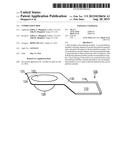
[0011] FIG. 1 is a top perspective view of a first embodiment of a dish.
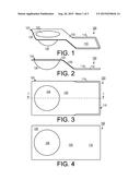
[0012] FIG. 2 is a side elevational view of the embodiment shown in FIG. 1.
[0013] FIG. 3 is a top plan view of the embodiment shown in FIG. 1.
[0014] FIG. 4 is a bottom plan view of the embodiment shown in FIG. 1.
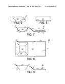
[0015] FIG. 5 is a left side elevational view of the embodiment shown in FIG. 1.
[0016] FIG. 6 is a right side elevational view of the embodiment shown in FIG. 1.
[0017] FIG. 7 is a cross-sectional view of the embodiment shown in FIG. 3, taken along line 7-7.
[0018] FIG. 8 is a top plan view of a second embodiment of a dish.
[0019] FIG. 9 is a side elevational view of the embodiment shown in FIG. 8.
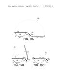
[0020] FIGS. 10A-10C are a series of side elevational views of a third embodiment of a dish.
DETAILED DESCRIPTION OF THE INVENTION
[0021] A preferred embodiment of the invention is now described in detail. Referring to the drawings, like numbers indicate like parts throughout the views. Unless otherwise specifically indicated in the disclosure that follows, the drawings are not necessarily drawn to scale. As used in the description herein and throughout the claims, the following terms take the meanings explicitly associated herein, unless the context clearly dictates otherwise: the meaning of "a," "an," and "the" includes plural reference, the meaning of "in" includes "in" and "on."
[0022] As shown in FIGS. 1-7, one embodiment of a dish 100 includes a first platform member 110 that is coupled to a second platform member 120 by a ramp 130. The first platform member 110 includes a peripheral lip 114 extending upwardly from the outer edges of the first platform 110. The second platform includes a flat portion 122 that defines hole 124 (which is circular in the embodiment shown, but could have one of many other shapes, including: oval, square, rectangular, triangular, polygonal, irregular, etc.) passing therethrough and a bowl 126 that opens to the hole 124 and that depends downwardly therefrom to the elevation of the first platform member 110. The first platform member 110 is configured to hold solid food 12 (such as a sandwich) thereon and the bowl 126 is configured to hold liquid food 10 (such as soup) and the like therein.
[0023] The dish 100 can be made from any material that dinnerware is typically made from, including, but no limited to: ceramic, glass, wood, bamboo, plastic, plastic composite, foam, melamine, stainless steel, aluminum, metal, paper, and natural fiber composites.
[0024] The method of making the dish 100 depends upon the material from which it is made according to methods well known in the art. For example, if it is made from a thermoplastic, it can either be injection molded or thermoformed; a ceramic embodiment would typically be slip cast and a metal embodiment could be stamped.
[0025] As shown in FIGS. 8 and 9, one embodiment of a dish 200 could include a polyhedronal bowl 226 that opens to a polygonal hole 224 defined by the first platform member 120. While the figures show a four sided bowl 226, it could have any number sides.
[0026] In one embodiment of a dish 300, as shown in FIGS. 10A-10B, the ramp structure 330 includes a first portion 334 that is coupled to a second portion 332 by a hinge 336. The platform member 110 can be moved from a first position, as shown in FIG. 10A, to a second position, as shown in FIG. 10C, wherein the platform member 110 acts as a cover for the bowl 126. The bowl 126 may have a flat bottom surface 328 to improve stability. When this embodiment is made of foam or paperboard, for example, as used in a restaurant "to-go" dish/container, the hinge 336 could simply be a line scored across the ramp structure 330 to facilitate easy folding thereof.
[0027] The above described embodiments, while including the preferred embodiment and the best mode of the invention known to the inventor at the time of filing, are given as illustrative examples only. It will be readily appreciated that many deviations may be made from the specific embodiments disclosed in this specification without departing from the spirit and scope of the invention. Accordingly, the scope of the invention is to be determined by the claims below rather than being limited to the specifically described embodiments above.
User Contributions:
Comment about this patent or add new information about this topic:
Images included with this patent application:
 |  |
 |  |
| New patent applications in this class: | |
| Date | Title |
|---|---|
| 2022-09-08 | Shrub rose plant named 'vlr003' |
| 2022-08-25 | Cherry tree named 'v84031' |
| 2022-08-25 | Miniature rose plant named 'poulty026' |
| 2022-08-25 | Information processing system and information processing method |
| 2022-08-25 | Data reassembly method and apparatus |