Patent application title: FOUNDATIONLESS TOWER ASSEMBLY
Inventors:
Charles Anderson (San Angelo, TX, US)
IPC8 Class: AE04H1222FI
USPC Class:
Class name:
Publication date: 2015-07-16
Patent application number: 20150197957
Abstract:
A tower assembly having a tower, the tower assembly for maintaining the
tower in a vertically upright position wherein the tower nor any part of
the tower assembly penetrates the ground on which the tower is disposed.
The tower of the tower assembly has a near end and a removed end, the
near end being attached to a tray having a flat floor and upstanding
vertical perimeter side walls. A mounting assembly mounts the tower to
the tray. A ballast, typically comprising multiple small stones, is
provided for laying on top of the flat floor of the tray, so as to
provide sufficient weight to prevent the tower from tipping over.Claims:
1. A tower assembly comprising: a tower having a near end and a removed
end; a tray having a flat floor and upstanding vertical perimeter side
walls; and a mounting assembly for engaging the tower to the tray; a
ballast comprising multiple stones for laying on top of the flat floor of
the tray.
2. The tower assembly of claim 1, wherein the mounting assembly has leveling members.
3. The tower assembly of claim 2, wherein the leveling members include multiple fasteners.
4. The tower assembly of claim 3, wherein the leveling members include a plate at the near end of the tower and a plate engaging the tray.
5. The tower assembly of claim 1, wherein the tower comprises a single mast.
6. The tower assembly of claim 5, wherein the single mast includes a swing tube and antenna.
7. The tower assembly of claim 1, wherein the tray includes a rectangular perimeter and multiple members defining cross members.
8. The tower assembly of claim 1, wherein the tray includes a first portion and a second portion, the two portions removably attached with fasteners.
9. The tower assembly of claim 8, wherein the two portions include cooperating telescoping members.
10. The tower assembly of claim 7, wherein the tray includes a rectangular perimeter and multiple members defining cross members; and wherein the tray includes a first portion and a second portion, the two portions removably attached with fasteners.
11. The tower assembly of claim 1, further including a flexible member for engaging the tray and substantially covering the ballast.
12. The tower assembly of claim 1, further including rigid diagonal braces for engaging the tray to the mast.
13. The tower assembly of claim 1, wherein the ballast is railroad ballast.
14. A tower assembly comprising: a tower having a near end and a removed end; a tray having a flat floor and upstanding vertical perimeter side walls; and a mounting assembly for engaging the tower to the tray; a ballast comprising multiple stones for laying on top of the flat floor of the tray; wherein the mounting assembly has leveling members; wherein the tower comprises a single mast; wherein the single mast includes a swing tube and antenna; wherein the tray includes a rectangular perimeter and multiple members defining cross members; and wherein the tray includes a first portion and a second portion, the two portions removably attached with fasteners.
15. The tower assembly of claim 14, further including a flexible member for engaging the tray and substantially covering the ballast.
16. The tower assembly of claim 14, further including rigid diagonal braces for engaging the tray to the mast.
17. The tower assembly of claim 11, wherein the mounting assembly has leveling members; and wherein the leveling members include multiple fasteners.
18. The tower assembly of claim 17, wherein the leveling members include a plate at the near end of the tower and a plate engaging the tray.
19. The tower assembly of claim 14, wherein the ballast is railroad ballast.
20. The tower assembly of claim 14, further including an equipment box.
Description:
[0001] This is a utility patent application, which claims the benefit of
and priority to U.S. Application Ser. No. 61/927,108, filed Jan. 14,
2014. The following applications are herein incorporated by reference: US
Patent Publication No. 2012/0291368, published Nov. 22, 2012; and U.S.
patent application Ser. No. 13/870,290, filed Apr. 25,2013, U.S. Pat. No.
8,863,450.
FIELD OF THE INVENTION
[0002] A foundationless tower assembly, more specifically, a tower supported by a ballast receiving tray resting on, but not penetrating, the ground.
BACKGROUND OF THE INVENTION
[0003] Typically, towers and other similar devices, such as towers for supporting an antenna at a removed end thereof, have foundations. Foundations penetrate the ground and are typically made of concrete. They provide stability because of a firm engagement of the tower to the ground. Towers, because of their elongated nature, have inherent instability, and need to be securely engaged with the ground or other support surface.
[0004] In some cases, it may not be possible to penetrate the ground, either for practical reasons or for political considerations. In such a case, where a tower needs to be erected, it may be useful to provide a support assembly for a tower that does not require disturbing the ground.
SUMMARY OF THE INVENTION
[0005] Applicant provides various embodiments of a tower assembly comprising a tower having a near and a removed end, the removed end for engaging an antenna and a near end adjacent the ground for engaging a tray resting on the ground. The tray is typically constructed with a flat floor and low or high upright side walls, and is designed to receive ballast, such as dirt, soil, a multiplicity of stones or rocks, or other suitable structures thereon. With a tray of sufficient size and stoutness, and with ballast received thereon and/or therein, a suitable foundationless support may be provided for the tower assembly, the support laying on the surface of the ground and not disturbing the ground.
[0006] One particular embodiment of Applicant's tray includes a mounting assembly for engaging the tower to the tray, which mounting assembly has a leveling mechanism for maintaining the axis of the tower vertical with respect to a generally horizontal support surface.
[0007] In another embodiment, Applicant provides for a tray that includes a breakdown assembly adapted to provide for ease of shipment and minimizing at least one long dimension of a tray.
[0008] A tower assembly comprising a tower having a near end and a removed end; a tray having a flat floor and upstanding vertical perimeter side walls; and a mounting assembly for engaging the tower to the tray, a ballast comprising multiple stones for laying on top of the flat floor of the tray; wherein the mounting assembly has leveling members; wherein the leveling members include multiple fasteners; wherein the leveling members include a plate at the near end of the tower and a plate engaging the tray; wherein the tower comprises a single mast; wherein the single mast includes a swing tube and antenna; wherein the tray includes a rectangular perimeter and multiple members defining cross members; wherein the tray includes a first portion and a second portion, the two portions removably attached with fasteners; wherein the two portions include cooperating telescoping members; wherein the tray includes a rectangular perimeter and multiple members defining cross members; and wherein the tray includes a first portion and a second portion, the two portions removably attached with fasteners. The tower assembly further may include a flexible member for engaging the tray and substantially covering the ballast, further may include rigid diagonal braces for engaging the tray to the mast, the ballast may be railroad ballast.
[0009] A tower assembly comprising a tower having a near end and a removed end, a tray having a flat floor and upstanding vertical perimeter side walls; and a mounting assembly for engaging the tower to the tray, a ballast comprising multiple stones for laying on top of the flat floor of the tray; wherein the mounting assembly has leveling members; wherein the tower comprises a single mast; wherein the single mast includes a swing tube and antenna; wherein the tray includes a rectangular perimeter and multiple members defining cross members; and wherein the tray includes a first portion and a second portion, the two portions removably attached with fasteners., further including a flexible member for engaging the tray and substantially covering the ballast, further including rigid diagonal braces for engaging the tray to the mast; wherein the mounting assembly has leveling members; wherein the leveling members include multiple fasteners; wherein the leveling members include a plate at the near end of the tower and a plate engaging the tray; and wherein the ballast is railroad ballast.
BRIEF DESCRIPTION OF THE DRAWINGS
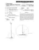
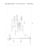
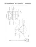
[0010] FIGS. 1 and 1 Detail A illustrate a side elevational view of the tower assembly, including details of a mounting assembly for mounting the tower of the tower assembly to a tray.
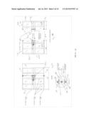
[0011] FIGS. 2A and 2B are side and top views of the tower assembly.
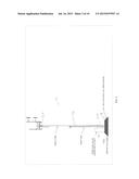
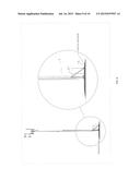
[0012] FIG. 3 is a side view of the tower assembly showing the tray stacked or filled with ballast above grade.
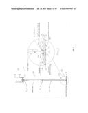
[0013] FIGS. 4 and 4 Detail A is another side view with detail showing features of the tray, the tower and method of mounting the tray to the tower.
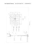
[0014] FIGS. 5A, 5A Detail, and 5B are top views showing the breakdown assembly of the tray in assembled form FIG. 5A; in disassembled form FIG. 5B. FIG. 5C is a perspective view of the breakdown assembly.
[0015] FIG. 6 shows a side view of Applicant's tower assembly with ballast above ground and additional features.
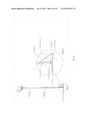
[0016] FIG. 7 shows a perspective view of the tray in a high wall embodiment thereof.
[0017] FIGS. 8A, 8A Detail, and 8B illustrate side and top views.
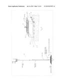
[0018] FIG. 9, 9 Detail, FIGS. 10, and 10 Detail are side views of a diagonally braced embodiment of Applicant's tower assembly.
DETAILED DESCRIPTION OF THE PREFERRED EMBODIMENT
[0019] The Figures illustrate a tower assembly 10 for erecting upon ground which ground cannot be disturbed or dug into. Tower assembly 10 may include a vertical tower 12 having a near end 12a and a removed end 12b, the removed end which may include a baseplate 12c as, for example 1/4 inch metal plate. In one embodiment, a pivotable antenna 13 may be provided at or near the removed end of the tower, the antenna for communication (send and/or receive) to and from a remote location, in one embodiment, the antenna for railroads. In one embodiment, the tower is a monopole and in another embodiment includes a base tube/swing tube combination (see U.S. Publication No. 2012/0291368).
[0020] It is seen that the overall design of Applicant's tower assembly is to provide tower 12 with a tray 14 engaging the near end 12 of the tower, which tray 14 is adapted to lay upon an outer surface, but not penetrate, a ground elevation, such as the surface of the ground, at the location where the tower assembly is located. That is to say, Applicant provides a tray 14 that is adapted to provide support and stability to tower 12 without penetrating the ground below or near the tower. The tower assembly typically includes ballast 18, which may be a multiplicity of rocks, for example, rocks about 1/2 inch to 4 or more inches in longest dimension, in which tray has a frame 22, the frame include upstanding perimeter members 30/32/34/36 and a floor 24 welded to or otherwise engaged fully beneath the frame. Thus, in general construction, tray 14 has a floor with upstanding side members, so as to at least partially contain the ballast 18 received therein. Floor 24 may be expanded steel mesh and frame 22 may be comprised of multiple square tubing welded up to one another to form the grid pattern as seen, for example, in FIG. 5A.
[0021] Equipment/accessory box 20 may also be provided as part of the tower assembly for engagement with tray 14, which equipment/accessory box 20 may contain electronic equipment and may receive cables from the antenna at the end of the tower.
[0022] Frame 22 is seen to include the perimeter members, as well as cross-members 38/40, which cross-members are designed to form a grid pattern and extend from one perimeter member to the opposite, the parallel trending members to provide rigidity and weight to the frame and to help secure ballast. It is seen that perimeter members 30/32/34/36 have some vertical height that act as side walls extending above floor 24 to help prevent lateral movement of the ballast, the ballast preferably providing a weight bearing function to the floor, such that the stabilization weight of the tray and ballast, as well as the moment arms provided by the perimeter, is sufficient to provide stability to the tower so that it will not tip even in a strong wind.
[0023] It is seen that there are a multiplicity of cross-members 38 and a multiplicity of cross-members 40. It is further seen, for example, with reference to FIG. 2B, that the cross-members may engage, as by welding or other means, the floor and each other, so as to provide a rigid grid-like frame that resists deflection, twisting, bending or other forces applied to it through engagement with the tower.
[0024] Some of the details of the mounting assembly are illustrated in FIG. 4. Mounting assembly 16 may include an upper rectangular support plate 44 welded or otherwise mounted to the upper surface of cross-members 40 and a support plate 42 welded to the lower surface of 40 and between cross-members 38a/38b. A support plate 12c may be welded to or otherwise engaged the near end 12a of tower 12 and support plate 12c may receive a multiplicity of mounting bolts 46 therethrough, which mounting bolts are entrained on holes through plates 42/44/12a to securely and directly fasten plate 12c and thus tower 12 to frame 22. The direct engagement of plate 12c flush against plate 44 is not illustrated, but illustrated in FIG. 4 Detail A is a mounting assembly that provides secure engagement of the tower to the frame, but additionally provides for plate 12c to be mounted at a slight angle with respect to the plane of the frame if it is necessary to provide vertical alignment of the tower. This is provided by the use of leveling nuts 50, one each at the four corners abutting lower surface of plate 12c, which may be adjusted, with the use of a level, to provide for such vertical alignment with the bolts engaging the top surface of plate 12c being tightened down after alignment is provided. Weldments 60 are seen to secure support plates 42/44 to the cross-members 40.
[0025] FIGS. 5A, 5B, and 5C illustrate a breakdown assembly 52 for engaging several of the cross-member 40 and perimeter members 34/36 in such a manner that they may disengage tray 14 from one portion 14a thereof to the other 14b, except the frame may be broken into two sections for ease of shipping. Breakdown assembly 52 may include paired corner brackets 54/56 provided on, typically, three sides of adjacent sections of the cross-members and perimeter members as seen in FIGS. 5A and 5B, with fastener 58 for engaging the paired corner brackets, which may be secured by weldment 60 or other suitable means to the adjacent sections of the cross-members/perimeter members as seen in the Figures. Additionally, the floor is typically cut into two sections 24a/24b. Note in FIG. 5B, cooperating telescoping members 70a (male)/70b (female) on at least some of the cross-members. There is seen that the sections of the cross-members and perimeter members are located so as to avoid cutting the mounting plates for mounting assembly. FIG. 5C shows additional optional features, including floor tab/fastener assemblies to engage butting edges of floor sections 24a/24b together.
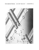
[0026] FIG. 7 illustrates for a "high walled" embodiment of frame 22. Perimeter members and cross-members may allow, in the earlier embodiments, walls of several inches high (measured from the floor up). That is, perimeter members, for example, if they are three, four, five or six by rectangular tube stock may provide perimeter side walls of 6' (3''×3'' perimeter) up to about 12 inches (6''×6'' perimeter). In the embodiment of FIG. 7, side wall members 62a-62d may extend up the perimeter members, up to 24'' or more high, so as to help contain ballast. Upstanding side wall members 62a-62d may be 1/4 or 1/8 inch sheet metal or sheet steel and provide for additional containment of ballast therein. The ballast used may be railroad ballast. This is angular crushed stone, in one case, about 1 3/4'' or 1 1/4'' to about 1/2'' limestone.
[0027] FIGS. 8A, 8B, 9 and 10 illustrate that diagonal support braces 64/66 may be used engaging cross-members and/or perimeter members to portions of the lower end of the tower, so as to help provide stability thereto. Diagonal braces may be engaged to plates on the lower end of the tower and may be engaged to perimeters or cross-members by a plate fastener combination (see, for example, detail FIG. 9). Note that braces 64/66 may be asymmetrical in the top view (FIG. 8B) to allow for the swing tube to swing. In monopole applications (no swing tube), braces may be symmetrically arranged around the tower and tray.
[0028] Materials for use in the frame perimeter and cross-members may include 3, 4 or 5 inch square tubing or other suitable dimensioned and shaped tubing, 1/4 inch, 5/16 inch or 3/8 inch walled or any other suitable wall thickness. I-beams may also be used for the frame. The frame or other metal surface may be galvanized, painted, powder coated or otherwise treated. Guywires (not shown) may extend diagonally downward from the body of the tower to stakes driven into the ground an area away from the tray. Optionally, ballast rock may be soil or other weight providing aggregate. The ballast may be provided with sloped sides (see, for example, in FIG. 3). The trusses or braces as seen in FIGS. 8-10 may be used to help stabilize and decrease the size and/or load of the tray needed. In the drawings, you may see exemplar dimensions and tray sizes (from about 6' on a side to about 10', and below are examples at 40 and 60 foot tower, moment, shear, and axial, with the tray weight with ballast given in Kips (one Kip=1,000 pounds).
[0029] 60' Tower Tray Foundation
[0030] Tower Base Reactions
[0031] Moment--99.5 Kip-Ft
[0032] Shear--2.8 Kips
[0033] Axial--2.7 Kips
[0034] Tray weight with ballast: about 24 Kips
[0035] 40' Tower Tray Foundation
[0036] Tower Base Reactions
[0037] Moment--42.1 Kip-Ft
[0038] Shear--1.6 Kips
[0039] Axial--1.6 Kips
[0040] Tray weight with ballast: about 13.5 Kips
[0041] The above are examples only and different size/weight towers may require different tray and ballast specifications.
[0042] Although the invention has been described with reference to a specific embodiment, this description is not meant to be construed in a limiting sense. On the contrary, various modifications of the disclosed embodiments will become apparent to those skilled in the art upon reference to the description of the invention. It is therefore contemplated that the appended claims will cover such modifications, alternatives, and equivalents that fall within the true spirit and scope of the invention.
User Contributions:
Comment about this patent or add new information about this topic:
Images included with this patent application:
 |  |
 |  |
 |  |
 |  |
 |  |
 |
| New patent applications in this class: | |
| Date | Title |
|---|---|
| 2022-09-08 | Shrub rose plant named 'vlr003' |
| 2022-08-25 | Cherry tree named 'v84031' |
| 2022-08-25 | Miniature rose plant named 'poulty026' |
| 2022-08-25 | Information processing system and information processing method |
| 2022-08-25 | Data reassembly method and apparatus |
| New patent applications from these inventors: | |
| Date | Title |
|---|---|
| 2015-03-19 | Titl tower assembly and a method of using the same, and a method to ship and assemble a tilt tower |
| 2015-01-22 | Tilt tower and pipe auger anchor assembly |
| 2014-09-11 | Tilt tower and pipe auger anchor assembly |
| 2012-11-22 | Tilt tower assembly and a method of using the same, and a method to ship and assemble a tilt tower |