Patent application title: SELECTIVE INTERNAL DISTRIBUTION OF ENGINE MOTOR OIL
Inventors:
Christofer J. Palumbo (Elmwood Park, IL, US)
Assignees:
International Engine Intellectual Property Company LLC
IPC8 Class: AF01P308FI
USPC Class:
Class name:
Publication date: 2015-07-09
Patent application number: 20150192058
Abstract:
Engine motor oil drawn from an oil sump by an oil pump is forced to flow
through a primary flow path to moving engine parts at pressures spanning
a first pressure range and a second pressure range which is greater than
the first pressure range. When pressure is within the first pressure
range, some engine motor oil flow may be diverted to a secondary flow
path having piston cooling jets which spray engine motor oil toward
undercrown surfaces of engine pistons. When pressure is within the second
pressure range, some engine motor oil flow is diverted to the piston
cooling jets and also to a tertiary flow path which may be a return to
the oil sump.Claims:
1. An internal combustion engine comprising: an oil sump for holding
engine motor oil; an oil pump for forcing engine motor oil drawn from the
oil sump to flow under pressure through a primary flow path for
delivering engine motor oil to moving parts of the engine including parts
operatively associated with pistons which reciprocate within engine
cylinders; a pressure regulating mechanism comprising an inlet port which
is open to the primary flow path at a location between the oil pump and
the moving parts of the engine, a first outlet port, and a second outlet
port, the pressure regulating mechanism being responsive to a first range
of oil pressure at the inlet port for controlling flow of engine motor
oil from the primary flow path to the first outlet port while disallowing
engine motor oil flow to the second outlet port, the pressure regulating
mechanism being responsive to a second range of oil pressure at the inlet
port greater than the first range of oil pressure to provide for engine
motor oil to flow from the primary flow path both to the first outlet
port and to the second outlet port; and a secondary flow path through
which engine motor oil is delivered from the first outlet port to the
pistons.
2. The internal combustion engine as set forth in claim 1 in which the secondary flow path comprises cooling jets through which engine motor oil is sprayed toward undercrown surfaces of the pistons.
3. The internal combustion engine as set forth in claim 1 comprising a tertiary flow path for engine motor oil to flow from the second outlet port.
4. The internal combustion engine as set forth in claim 1 in which the pressure regulating mechanism is contained within a housing which comprises a passage having an end open to the primary flow path, the pressure regulating mechanism comprising a plunger which is displaceable within the passage and is biased by a spring toward the end of the passage open to the primary flow path to seat on a seat surface of the housing in the absence of any oil pressure at the inlet port.
5. The internal combustion engine as set forth in claim 4 including a leak path for oil to flow from the primary flow path to the first outlet port when the plunger seats on the seat surface of the housing.
6. The internal combustion engine as set forth in claim 5 in which the leak path for oil to flow from the primary flow path to the first outlet port when the plunger seats on the seat surface of the housing is cooperatively defined between the plunger and the seat surface of the housing.
7. An internal combustion engine comprising: an oil sump for holding engine motor oil; an oil pump for forcing engine motor oil drawn from the oil sump to flow under pressure through a primary flow path for delivering engine motor oil to moving parts of the engine including parts operatively associated with pistons which reciprocate within engine cylinders; a pressure regulating mechanism comprising an inlet port which is open to the primary flow path at a location between the oil pump and the moving parts of the engine, a first outlet port, and a second outlet port; and a secondary flow path for engine motor oil to flow from the first outlet port to cooling jets which are arranged to spray engine motor oil toward undercrown surfaces of the pistons; the pressure regulating mechanism being operative, as a function of oil pressure at the inlet port, to selectively control flow of engine motor oil from the primary flow path to the first outlet port and to the second outlet port.
8. The internal combustion engine as set forth in claim 7 in which the pressure regulating mechanism is operative, for a first range of oil pressure at the inlet port, to control flow of engine motor oil from the primary flow path to the first outlet port while disallowing engine motor oil flow to the second outlet port, and for a second range of oil pressure at the inlet port greater than the first range of oil pressure to provide a flow path for engine motor oil from the primary flow path both to the first outlet port and to the second outlet port.
9. The internal combustion engine as set forth in claim 7 comprising a tertiary flow path for engine motor oil to flow from the second outlet port.
10. The internal combustion engine as set forth in claim 7 in which the pressure regulating mechanism is contained within a housing which comprises a passage having an end open to the primary flow path, the pressure regulating mechanism comprising a plunger which is displaceable within the passage and is biased by a spring toward the end of the passage open to the primary flow path to seat on a seat surface of the housing in the absence of any oil pressure at the inlet port.
11. The internal combustion engine as set forth in claim 10 including a leak path for oil to flow from the primary flow path to the first outlet port when the plunger seats on the seat surface of the housing.
12. The internal combustion engine as set forth in claim 11 in which the leak path for oil to flow from the primary flow path to the first outlet port when the plunger seats on the seat surface of the housing is cooperatively defined between the plunger and the seat surface of the housing.
13. A method of internally distributing engine motor oil within an internal combustion engine, the method comprising: forcing engine motor oil drawn by a pump from an oil sump to flow at oil pressures spanning a first pressure range and a second pressure range which is greater than the first pressure range through a primary flow path which delivers engine motor oil to moving parts of the engine, including parts operatively associated with pistons which reciprocate within engine cylinders; selectively controlling, as a function of oil pressure in the primary flow path, flow of some engine motor oil from the primary flow path through a secondary flow path comprising cooling jets which are arranged to spray engine motor oil toward undercrown surfaces of the pistons and through a tertiary flow path such that when oil pressure in the primary flow path is within the first pressure range, engine motor oil flow through the secondary flow path is controlled and engine motor oil flow through the tertiary flow path is disallowed, and when oil pressure in the primary flow path is within the second pressure range, engine motor oil flows both through the secondary flow path and through the tertiary flow path.
Description:
TECHNICAL FIELD
[0001] The subject matter of this disclosure relates to selective distribution of engine motor oil internally of an internal combustion engine, including selective distribution to piston cooling jets through which engine motor oil is sprayed toward undercrown surfaces of pistons which reciprocate within engine cylinders.
BACKGROUND
[0002] An internal combustion engine may comprise piston cooling jets through which engine motor oil is sprayed onto undercrown surfaces of pistons which are reciprocating within engine cylinders within which fuel combusts to power the engine. The intent of such spraying is to provide some cooling of the pistons.
[0003] A known engine oil circuit comprises an oil pump which draws engine motor oil from an oil sump and forces the oil under pressure through internal oil passages to lubricate surfaces which are subject to moving friction. The engine oil circuit of an internal combustion engine which comprises piston cooling jets also forces some of the pumped oil to be sprayed through the piston cooling jets onto piston surfaces which may not be subject to moving friction, especially piston undercrown surfaces, for the purpose of cooling the pistons.
SUMMARY
[0004] A general aspect of the disclosed subject matter relates to an internal combustion engine comprising an oil sump for holding engine motor oil and an oil pump for forcing engine motor oil drawn from the oil sump to flow under pressure through a primary flow path for delivering engine motor oil to moving parts of the engine including parts operatively associated with pistons which reciprocate within engine cylinders.
[0005] A pressure regulating mechanism comprises an inlet port which is open to the primary flow path at a location between the oil pump and the moving parts of the engine, a first outlet port, and a second outlet port.
[0006] The pressure regulating mechanism is responsive to a first range of oil pressure at the inlet port for controlling flow of engine motor oil from the primary flow path to the first outlet port while disallowing engine motor oil flow to the second outlet port.
[0007] The pressure regulating mechanism is responsive to a second range of oil pressure at the inlet port greater than the first range of oil pressure to provide for engine motor oil to flow from the primary flow path both to the first outlet port and to the second outlet port.
[0008] Another general aspect relates to an internal combustion engine comprising an oil sump for holding engine motor oil and an oil pump for forcing engine motor oil drawn from the oil sump to flow under pressure through a primary flow path for delivering engine motor oil to moving parts of the engine including parts operatively associated with pistons which reciprocate within engine cylinders.
[0009] A pressure regulating mechanism comprises an inlet port which is open to the primary flow path at a location between the oil pump and the moving parts of the engine, a first outlet port, and a second outlet port.
[0010] A secondary flow path provides for engine motor oil to flow from the first outlet port to cooling jets which are arranged to spray engine motor oil toward undercrown surfaces of the pistons.
[0011] The pressure regulating mechanism is operative, as a function of oil pressure at the inlet port, to selectively control flow of engine motor oil from the primary flow path to the first outlet port and to the second outlet port.
[0012] Another general aspect relates to a method of internally distributing engine motor oil within an internal combustion engine.
[0013] The method comprises forcing engine motor oil drawn by a pump from an oil sump to flow at oil pressures spanning a first pressure range and a second pressure range which is greater than the first pressure range through a primary flow path which delivers engine motor oil to moving parts of the engine, including parts operatively associated with pistons which reciprocate within engine cylinders.
[0014] The method further comprises selectively controlling, as a function of oil pressure in the primary flow path, flow of some engine motor oil from the primary flow path through a secondary flow path comprising cooling jets which are arranged to spray engine motor oil toward undercrown surfaces of the pistons and through a tertiary flow path such that when oil pressure in the primary flow path is within the first pressure range, engine motor oil flow through the secondary flow path is controlled and engine motor oil flow through the tertiary flow path is disallowed, and when oil pressure in the primary flow path is within the second pressure range, engine motor oil flows both through the secondary flow path and through the tertiary flow path
[0015] The foregoing summary, accompanied by further detail of the disclosure, will be presented in the Detailed Description below with reference to the following drawings that are part of this disclosure.
BRIEF DESCRIPTION OF THE DRAWINGS
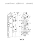
[0016] FIG. 1 is a schematic diagram of a portion of an internal combustion engine.
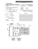
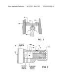
[0017] FIG. 2 is a cross section view through an engine cylinder within which a piston reciprocates.
[0018] FIG. 3 is a cross section view through a portion of a pressure regulator.
DETAILED DESCRIPTION
[0019] FIG. 1 illustrates a portion of an internal combustion engine 10 including an oil sump 12 comprising an oil pan for holding engine motor oil, an oil pump 14 for drawing engine motor oil from oil sump 12 and forcing engine motor oil to flow under pressure through a primary flow path 16 which delivers engine motor oil to moving parts of engine 10 including parts associated with pistons 18 which, as represented in FIG. 2, reciprocate within engine cylinders 20. Primary flow path 16 includes an oil cooler 22, an oil filter 24, and a passageway 26 through a pressure regulator 28 for delivering, via various internal passages and holes, lubrication for various moving parts including a camshaft 32 which rotates within camshaft bearings 34, a crankshaft 36 which rotates within main bearings 38, and connecting rods 40 (shown in FIG. 2) whose small ends are journaled on wrist pins 42 which are fit to the pistons' skirts to couple pistons 18 with throws of crankshaft 36.
[0020] FIG. 1 shows that primary flow path 16 also delivers engine motor oil for lubricating engine driven devices such as an air compressor 44 and a turbocharger 46, and for sourcing engine motor oil to a high-pressure system 48.
[0021] Passageway 26 through pressure regulator 28 forms a portion of primary flow path 16 leading to moving parts of engine 10 already described and provides pressure regulator 28 with an inlet port 50 which is open to oil pump 14 through oil filter 24 and oil cooler 22. Pressure regulator 28 further comprises a first outlet port 52 and a second outlet port 54.
[0022] A secondary flow path 56 branches from first outlet port 52. Some engine motor oil is diverted to secondary flow path 56 from primary flow path 16 under certain pressure conditions at inlet port 50 to be hereinafter described. When those conditions are present, secondary flow path 56 delivers engine motor oil to piston cooling jets 58 which spray engine motor oil toward undercrown surfaces 60 of pistons 18.
[0023] A tertiary flow path 62 branches from second outlet port 54. Some engine motor oil is diverted to tertiary flow path 62 from primary flow path 16 under a certain pressure condition at inlet port 50 to be hereinafter described. When that condition is present, tertiary flow path 62 returns engine motor oil to oil sump 12.
[0024] Pressure regulator 28 comprises a regulating mechanism 64 (an example of which will be described with reference to FIG. 3) which is responsive to a first range of oil pressure at inlet port 50 for controlling engine motor oil flow to first outlet port 52 while disallowing engine motor oil flow to second outlet port 54, and which is responsive to a second range of oil pressure at inlet port 50 greater than the first range of oil pressure, to provide for engine motor oil to flow both to first outlet port 52 and to second outlet port 54.
[0025] FIG. 3 shows one example of pressure regulator 28 as a mechanical pressure regulator valve having a housing 66 containing regulating mechanism 64. Regulating mechanism 64 comprises a plunger 68 and a coiled compression spring 70 which are disposed within a passage 72 which is open at an inner end to inlet port 50 through passageway 26. The outer end of passage 72 is closed by a plug 74.
[0026] With plunger 68 and spring 70 disposed in passage 72 and plug 74 closing the outer end of passage 72, spring 70 bears against plug 74 to assume a resiliently compressed condition which in the absence of oil pressure at inlet port 50, forces plunger 68 toward the end of passage 72 which is open through passageway 26 to inlet port 50 and to seat the plunger's tapered end on a seat surface 75 of housing 66. This condition is represented by the solid line position of plunger 68.
[0027] The nature of the sealing may be a full seal which closes both first outlet port 52 and second outlet port 54 to inlet port 50 or a partial seal which provides a small leak path from inlet port 50 to first outlet port 52 while closing second outlet port 54 to inlet port 50.
[0028] As oil pressure builds over the first range of oil pressures from no oil pressure at inlet port 50 toward an oil pressure representing an upper limit of the first range, plunger 68 will at some pressure determined by the force of spring 70 unseat from seat surface 75 and begin to be increasingly displaced away from passageway 26 with increasing oil pressure to allow more oil flow to first outlet port 52. When pressure at inlet port 50 reaches the upper limit of the first range, plunger 68 assumes the position represented by the broken line position 68A where it is still disallowing flow to second outlet port 54 although the possibility of some slight leakage may exist.
[0029] As oil pressure builds over the second range of oil pressures from the upper limit of the first range, plunger 68 is increasingly displaced away from passageway 26 with increasing oil pressure beyond broken line position 68A, allowing more oil to flow to second outlet port 54.
[0030] Oil pressure developed by oil pump 14 depends on various factors, one of which is engine speed. In general, oil pressure will increase with engine speed. Engine motor oil is delivered to the moving parts served by primary flow path 16. Depending on specific pressure regulator design, a pressure regulator may allow either no flow or leakage flow to first outlet port 52 until oil pressure developed by oil pump 14 reaches a pressure within the first range of pressures that unseats and begins to displace plunger 68. This may avoid delivery of engine motor oil to piston cooling jets 58 at low engine speeds where additional piston cooling may not be called for. At moderate engine speeds, engine motor oil is sprayed onto pistons 18, and at high engine speeds, piston cooling jets 58 continue to spray engine motor oil while pressure is limited by allowing flow through second outlet port 54.
[0031] Because use of piston cooling jets 58 is controlled by a common pressure regulator, each piston cooling jet may do without its own internal pressure regulation mechanism, allowing all piston cooling jets to operate in unison for promoting more uniform cooling of all pistons.
[0032] An engine may have the pressure regulator upstream of the oil cooler in which case an auxiliary cooler may be placed in the flow path to the piston cooling jets.
User Contributions:
Comment about this patent or add new information about this topic:
| People who visited this patent also read: | |
| Patent application number | Title |
|---|---|
| 20150353229 | BEVERAGE DELIVERY CAN |
| 20150353228 | Can/flass soda can. The new can opening. |
| 20150353227 | POURING PACKAGE FOR A FLUID AND POURING ELEMENT THEREFOR |
| 20150353226 | ASSEMBLY AND METHOD FOR CREATING CUSTOM THREE-DIMENSIONAL STRUCTURES FROM PRINTABLE BLANK SHEETS |
| 20150353225 | FACETED CONTAINER |
Images included with this patent application:
 |  |
 |
| New patent applications in this class: | |
| Date | Title |
|---|---|
| 2022-09-08 | Shrub rose plant named 'vlr003' |
| 2022-08-25 | Cherry tree named 'v84031' |
| 2022-08-25 | Miniature rose plant named 'poulty026' |
| 2022-08-25 | Information processing system and information processing method |
| 2022-08-25 | Data reassembly method and apparatus |
| New patent applications from these inventors: | |
| Date | Title |
|---|---|
| 2016-04-21 | Thermostat |
| 2013-08-15 | Engine braking system using spring loaded valve |
| 2012-07-26 | High pressure fuel pump piston assembly |
| 2011-03-03 | Breather air - oil seperator |
| 2011-02-10 | Bridge and pivot foot arrangement for operating engine cylinder valves |