Patent application title: Anti-Falling Device
Inventors:
Yi-Pin Liu (Taichung City, TW)
IPC8 Class: AA62B3500FI
USPC Class:
Class name:
Publication date: 2015-06-11
Patent application number: 20150157885
Abstract:
An anti-falling device contains: a support rod including a hanging seat
and ratchet teeth; two locking jaws, and each locking jaw having a fixing
mount, a controlling member, and a spring; the fixing mount having a
fitting orifice, an arcuate orifice, a receiving orifice, and a clamping
hook. The fitting orifice is fitted with the support rod, the arcuate
orifice passes through the fixing mount, the receiving orifice passes
through the fixing mount, two clamping hooks of the two locking jaws are
clamped on two end portions of an extending plate of a H beam. The
controlling member is connected with the fixing mount and swings between
a locking position and an unlocking position. The controlling member has
a lock bolt and two apertures, and the two inserting bolts are inserted
into the two apertures and the receiving orifice so as to limit the
controlling member at the locking position.Claims:
1. An anti-falling device comprising: a support rod including a hanging
seat for coupling with a safety rope on a worker, the support rod also
including a plurality of ratchet teeth defined thereon; two locking jaws
fitted on two ends of the support rod, and each locking jaw having a
fixing mount, a controlling member, and a spring; the fixing mount having
a fitting orifice, an arcuate orifice, a receiving orifice, and a
clamping hook; the fitting orifice being polygonal and fitted with the
support rod, the arcuate orifice passing through the fixing mount and
communicating with the fitting orifice, the receiving orifice passing
through two sides of the fixing mount adjacent to a top end thereof, two
clamping hooks of the two locking jaws being clamped on two end portions
of an extending plate of a H beam, the controlling member being connected
with the fixing mount and swinging between a locking position and an
unlocking position, the controlling member having a lock bolt inserted
into the arcuate orifice and having two apertures, when the controlling
member is located at the locking position, the lock bolt engages with one
of the plurality of ratchet teeth, and the two apertures align with the
receiving orifice; when the controlling member is located at an unlocking
position, the lock bolt disengages from one of the plurality of ratchet
teeth, and the spring being defined between the fixing mount and the
controlling member so as to push the controlling member to fix at the
locking position, and after two inserting bolts are removed from the two
apertures and the receiving orifice, they push the two locking jaws to
move to each other, such that the lock bolt engages with one of the
plurality of ratchet teeth; and the two inserting bolts inserted into the
two apertures and the receiving orifice so as to limit the controlling
member at the locking position.
2. The anti-falling device as claimed in claim 1, wherein the fixing mount also has a tilted face defined on an outer rim of a top surface thereof and a spring slot formed on the tilted face; the controlling member has a pressing piece and two side sheets, the pressing piece is disposed on the tilted face, and the two side sheets extend to the two recesses from the two pressing pieces, the lock has two ends coupling with the two side sheets, the two apertures are defined on the two side sheets, and the spring is mounted in the spring slot and has an upper end for abutting against a bottom end of the pressing piece.
3. The anti-falling device as claimed in claim 2, wherein the fixing mount also has two notches defined in the two recesses, and the two side sheets have two pegs inserted into the two notches.
4. The anti-falling device as claimed in claim 2, wherein the fixing mount also has two recesses arranged on two opposite sides thereof
5. The anti-falling device as claimed in claim 1, wherein each inserting bolt has a large-diameter head and a small-diameter stem inserting through the two apertures and the receiving orifice, the large-diameter head is fixed on a first end of a hanging rope, and a second end of the hanging rope is secured on the fixing mount.
6. The anti-falling device as claimed in claim 5, wherein a positioning element is secured on the second end of the hanging rope, and the positioning element is screwed on the fixing mount by a screw.
7. The anti-falling device as claimed in claim 1, wherein the support rod also includes two through holes passing through two ends thereof so as to insert two screw bolts, and then the two screw bolts are screwed with two nuts.
8. The anti-falling device as claimed in claim 1, wherein the support rod is hexagonal so as to fit with the fitting orifice.
9. The anti-falling device as claimed in claim 1, wherein the clamping hook has a lock groove defined thereon, such that two clamping hooks of the two locking jaws are clamped on the two end portions of the extending plate of the H beam.
10. The anti-falling device as claimed in claim 1, wherein each clamping hook having a protrusion and two rollers, a lock groove defined among the protrusion and the two rollers, such that the lock groove retains with the two end portions of the extending plate of the H beam.
Description:
FIELD OF THE INVENTION
[0001] The present invention relates to an anti-falling device which is operated easily and safely.
BACKGROUND OF THE INVENTION
[0002] A conventional anti-falling device is disclosed in TW Publication No. I349727 and contains a support rod having a plurality of ratchet teeth defined thereon, a hanging seat for hanging a safety rope on a worker, and two locking jaws fitted thereon. Each locking jaw has a movable clamper and a controlling member disposed on the movable clamper. The controlling member has a single-direction toothed member driven by a spring to engage with the plurality of ratchet teeth, such that the locking jaw move to each other along the support rod. The single-direction toothed member of the controlling member engages with and disengages from the plurality of ratchet teeth. When the two locking jaws inversely move along the support rod, the single-direction toothed member are engaged by the plurality of ratchet teeth, and then two controlling members drive the single-direction toothed member to disengage from the plurality of ratchet teeth, such that the two locking jaws move inversely along the support rod so as to retain a H beam.
[0003] However, when the two controlling members are pressed carelessly, the single-direction toothed member is driven to disengage from the plurality of ratchet teeth, thus operating the anti-falling device unsafely.
[0004] The present invention has arisen to mitigate and/or obviate the afore-described disadvantages.
SUMMARY OF THE INVENTION
[0005] The primary object of the present invention is to provide an anti-falling device which is operated easily and safely
[0006] To obtain the above objective, an anti-falling device provided by the present invention contains: a support rod, two locking jaws, and two inserting bolts.
[0007] The support rod includes a hanging seat for coupling with a safety rope on a worker; the support rod also includes a plurality of ratchet teeth defined thereon.
[0008] The two locking jaws are fitted on two ends of the support rod, and each locking jaw has a fixing mount, a controlling member, and a spring. The fixing mount has a fitting orifice, an arcuate orifice, a receiving orifice, and a clamping hook. The fitting orifice is polygonal and fitted with the support rod, the arcuate orifice passes through the fixing mount and communicates with the fitting orifice, the receiving orifice passes through two sides of the fixing mount adjacent to a top end thereof, two clamping hooks of the two locking jaws are clamped on two end portions of an extending plate of a H beam, the controlling member is connected with the fixing mount and swings between a locking position and an unlocking position, the controlling member has a lock bolt inserted into the arcuate orifice and two apertures, when the controlling member is located at the locking position, the lock bolt engages with one of the plurality of ratchet teeth, and the two apertures align with the receiving orifice; when the controlling member is located at an unlocking position, the lock bolt disengages from one of the plurality of ratchet teeth, and the spring is defined between the fixing mount and the controlling member so as to push the controlling member to fix at the locking position, and after two inserting bolts are removed from the two apertures and the receiving orifice, they push the two locking jaws to move to each other, such that the lock bolt engages with one of the plurality of ratchet teeth.
[0009] The two inserting bolts are inserted into the two apertures and the receiving orifice so as to limit the controlling member at the locking position.
BRIEF DESCRIPTION OF THE DRAWINGS
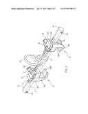
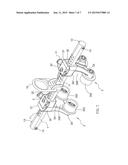
[0010] FIG. 1 is a perspective view showing the exploded components of an anti-falling device according to a first embodiment of the present invention.
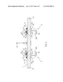
[0011] FIG. 2 is a perspective view showing the assembly of the anti-falling device according to the first embodiment of the present invention.
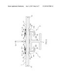
[0012] FIG. 3 is a cross sectional view showing the assembly of the anti-falling device according to the first embodiment of the present invention.
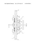
[0013] FIG. 4 is a cross sectional view showing the operation of the anti-falling device according to the first embodiment of the present invention.
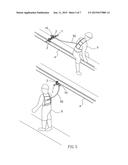
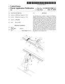
[0014] FIG. 5 is a perspective view showing the application of the anti-falling device according to the first embodiment of the present invention.
[0015] FIG. 6 is another cross sectional view showing the operation of the anti-falling device according to the first embodiment of the present invention.
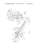
[0016] FIG. 7 is a perspective view showing the assembly of the anti-falling device according to a second embodiment of the present invention.
DETAILED DESCRIPTION OF THE PREFERRED EMBODIMENTS
[0017] With reference to FIGS. 1-6, an anti-falling device according to a first embodiment of the present invention comprises: a support rod 1, two locking jaws 2, and two inserting bolts 3.
[0018] The support rod is hexagonal and includes a hanging seat 10 for coupling with a safety rope 50 on a worker 5. The support rod 1 also includes a plurality of ratchet teeth 11 defined thereon, two through holes 12 passing through two ends thereof so as to insert two screw bolts 13, and then the two screw bolts 13 are screwed with two nuts 14.
[0019] The two locking jaws 2 are fitted on the two ends of the support rod 1, and each locking jaw 2 has a fixing mount 20, a controlling member 21, and a spring 22. The fixing mount 20 has a fitting orifice 23, an arcuate orifice 24, a receiving orifice 25, and a clamping hook 26. The fitting orifice 23 is polygonal and is fitted with the support rod 1, such that the fixing mount 20 axially moves along the support rod 1. The arcuate orifice 24 passes through the fixing mount 20 and communicates with the fitting orifice 23. The receiving orifice 25 passes through two sides of the fixing mount 20 adjacent to a top end thereof. The clamping hook 26 has a lock groove 260 defined thereon, such that two clamping hooks 26 of the two locking jaws 2 are clamped on two end portions of an extending plate 40 of a H beam 4. The fixing mount 20 also has a tilted face 200 defined on an outer rim of a top surface thereof, a spring slot 201 formed on the tilted face 200, two recesses 202 arranged on two opposite sides thereof, two notches 203 defined in the two recesses 202. The controlling member 21 is connected with the fixing mount 20 and swings between a locking position and an unlocking position. The controlling member 21 has a pressing piece 210, two side sheets 211, and a lock bolt 212. The pressing piece 210 is disposed on the tilted face 200, and the two side sheets 211 extend to the two recesses 202 from the two pressing pieces 210, the two side sheets 211 have two pegs 213 inserted into the two notches 293 and two apertures 214 for aligning with the receiving orifice 25. The lock bolt 212 is inserted into the arcuate orifice 24 and has two ends coupling with the two side sheets 211. The spring 22 is mounted in the spring slot 201 and has an upper end for abutting against a bottom end of the pressing piece 210 so as to push the controlling member 21 to fix at the locking position.
[0020] The two inserting bolts 3 are inserted into the two apertures 214 and the receiving orifice 25, such that the controlling member 21 is limited at the locking position. Each inserting bolt 3 has a large-diameter head 30 and a small-diameter stem 31 inserting through the two apertures 214 and the receiving orifice 25. The large-diameter head 30 is fixed on a first end of a hanging rope 32, and a positioning element 33 is secured on a second end of the hanging rope 32 and is screwed on the top surface of the fixing mount 20 by a screw 34.
[0021] Referring to FIGS. 1 and 3, the spring 22 pushes the controlling member 21 to fix at the locking position, and when the controlling member 21 is located at the locking position, the lock bolt 212 engages with one of the plurality of ratchet teeth 11, and the two apertures 214 align with the receiving orifice 25, such that the two inserting bolts 3 are inserted into the two apertures 214 and the receiving orifice 25 so as to limit the controlling member 21 at the locking position.
[0022] As shown in FIGS. 1, 4 and 5, when the two inserting bolts 3 are removed from the two apertures 214 and the receiving orifice 25, the two locking jaws 2 are pushed so that two lock bolts 212 are driven to engage with two of the plurality of ratchet teeth 11, thus positioning the two locking jaws 2. Thereafter, the two locking jaws 2 clamp the H beam 4, and the safety rope 50 on the worker 5 is coupled with the hanging seat 10, hence when the worker 5 moves on the H beam 4, the safety rope 50 drives the anti-falling device to slide along the H beam 4. In addition, the two locking jaws 2 clamp the H beam 4 so as to protect the worker 5 from falling.
[0023] As illustrated in FIGS. 1 and 6, after the two inserting bolts 3 are removed from the two apertures 214 and the receiving orifice 25, the controlling member 21 is pressed to swing toward an unlocking position, such that the two lock bolts 212 disengage from two of the plurality of ratchet teeth 11, and the two apertures 214 do not align with the receiving orifice 25 so that the two locking jaws 2 are pushed outwardly from the H beam, thus unclamping the H beam 4.
[0024] Accordingly, the two locking jaws 2 are adjustably clamp the H beam 4 of varying size. Also, the two screw bolts 13 and the two nuts 14 are provided to prevent the two locking jaws 2 from disengagement from the two ends of the support rod 1.
[0025] With reference to FIG. 7, a difference of an anti-falling device of a second embodiment from that of the first embodiment comprises: two locking jaws 2 including two clamping hooks 26, and each clamping hook 26 having a protrusion 261 and two rollers 262, a lock groove 260 defined among the protrusion 261 and the two rollers 262, such that the lock groove 260 retains with two end portions of an extending plate 40 of a H beam 4, and the two rollers 262 of the two locking jaws 2 roll the anti-falling device on the H beam 4 smoothly.
[0026] Due to the two inserting bolts 3 are inserted into the two apertures 214 and the receiving orifice 25 of the two locking jaws 2, the controlling member 21 is limited at the locking position, such that the controlling member 21 will not be pressed carelessly to drive the lock bolt 212 to disengage from one of the plurality of ratchet teeth, thus avoiding the two locking jaws 2 unclamping the H beam 4 along the support rod 1. Furthermore, after the two inserting bolts 3 are removed from the two apertures 214 and the receiving orifice 25, they push the two locking jaws 2 to move to each other, such that the lock bolt 212 engages with one of the plurality of ratchet teeth 11, thereby clamping the H beam 4. After removing the two inserting bolts 3 from the two apertures 214 and the receiving orifice 25, the controlling member 21 is pressed to swing toward the unlocking position so that the lock bolt 212 disengages from one of the plurality of ratchet teeth 11, thereby unclamping the H beam 4 easily and quickly.
[0027] While the preferred embodiments of the invention have been set forth for the purpose of disclosure, modifications of the disclosed embodiments of the invention as well as other embodiments thereof may occur to those skilled in the art. Accordingly, the appended claims are intended to cover all embodiments which do not depart from the spirit and scope of the invention.
User Contributions:
Comment about this patent or add new information about this topic:
Images included with this patent application:
 |  |
 |  |
 |  |
 |  |
| New patent applications in this class: | |
| Date | Title |
|---|---|
| 2022-09-08 | Shrub rose plant named 'vlr003' |
| 2022-08-25 | Cherry tree named 'v84031' |
| 2022-08-25 | Miniature rose plant named 'poulty026' |
| 2022-08-25 | Information processing system and information processing method |
| 2022-08-25 | Data reassembly method and apparatus |