Patent application title: INDOOR COIL
Inventors:
Kevin Mercer (Danville, IN, US)
Kevin Mercer (Danville, IN, US)
Kevin B. Dunshee (Camillus, NY, US)
Assignees:
CARRIER CORPORATION
IPC8 Class: AF28F100FI
USPC Class:
Class name:
Publication date: 2015-06-04
Patent application number: 20150153111
Abstract:
An indoor coil including at least one coil slab. The at least one coil
slab including a pair of coil slab end surfaces extending between a pair
coil slab faces, a coil slab axis, and a plurality of conduits, operably
coupled to one another, disposed therein. One of the pair of coil slab
end surfaces forms an angle greater than or equal to 45 degrees and less
than 90 degrees with the coil slab axis, and the plurality of conduits
are arranged in a staggered configuration.Claims:
1. An indoor coil comprising: at least one coil slab including a pair of
coil slab end surfaces extending between a pair coil slab faces, and a
coil slab axis; a plurality of conduits, operably coupled to one another,
disposed within the at least one coil slab. wherein one of the pair of
coil slab end surfaces forms an angle greater than or equal to 45 degrees
and less than 90 degrees with the coil slab axis; wherein the plurality
of conduits are arranged in a staggered configuration.
2. The indoor coil of claim 1, wherein the other of the pair of coil slab end surfaces forms an angle greater than or equal to 45 degrees and less than 90 degrees with the coil slab axis.
3. The indoor coil of claim 1, wherein the at least one coil slab comprises a first coil slab and a second coil slab.
4. The indoor coil of 3, wherein the first coil slab and the second coil slab are arranged in a "V" configuration.
5. A fan coil assembly comprising: a cabinet; an indoor coil disposed within the cabinet, wherein the indoor coil comprises: at least one coil slab including a pair of coil slab end surfaces extending between a pair coil slab faces, and a coil slab axis; a plurality of conduits, operably coupled to one another, disposed within the at least one coil slab. wherein one of the pair of coil slab end surfaces forms an angle greater than or equal to 45 degrees and less than 90 degrees with the coil slab axis; wherein the plurality of conduits are arranged in a staggered configuration.
6. The fan coil assembly of claim 5, wherein the other of the pair of coil slab end forms an angle greater than or equal to 45 degrees and less than 90 degrees with the coil slab axis.
7. The fan coil assembly of claim 5, further comprising a fan disposed within the cabinet.
8. The fan coil assembly of claim 5, further comprising an auxiliary heating assembly disposed within the cabinet.
9. The fan coil assembly of claim 5, wherein the at least one coil slab comprises a first coil slab and a second coil slab.
10. The fan coil assembly of claim 9, wherein the first coil slab and the second coil slab are arranged in a "V" configuration.
11. An HVAC system comprising: a heat pump; a fan coil assembly, including an indoor coil and a fan disposed within a cabinet, operably coupled to the heat pump; wherein the indoor coil comprises: at least one coil slab including pair of coil slab end surfaces extending between a pair coil slab faces, and a coil slab axis; a plurality of conduits, operably coupled to one another, disposed within the at least one coil slab; wherein one of the pair of coil slab end surfaces forms an angle greater than or equal to 45 degrees and less than 90 degrees with the coil slab axis; wherein the plurality of conduits are arranged in a staggered configuration.
12. The HVAC system of claim 11, wherein the other of the pair of coil slab end forms an angle greater than or equal to 45 degrees and less than 90 degrees with the coil slab axis.
13. The HVAC system of claim 12, further comprising an auxiliary heating assembly disposed within the fan coil assembly
14. The HVAC system of claim 11, wherein the at least one coil slab comprises a first coil slab and a second coil slab.
15. The HVAC system of claim 14, wherein the first coil slab and the second coil slab are arranged in a "V" configuration.
Description:
CROSS REFERENCE TO RELATED APPLICATIONS
[0001] The present application is related to, and claims the priority benefit of, U.S. Provisional Patent Application Ser. No. 61/910,716 filed Dec. 2, 2013, the contents of which are hereby incorporated in their entirety into the present disclosure.
TECHNICAL FIELD OF THE DISCLOSED EMBODIMENTS
[0002] The presently disclosed embodiments generally relate to heating, ventilation, and air-conditioning (HVAC) systems, and more particularly, to an indoor coil.
BACKGROUND OF THE DISCLOSED EMBODIMENTS
[0003] In a conventional refrigerant cycle, a compressor compresses a refrigerant and delivers the compressed refrigerant to a downstream condenser coil. From the condenser coil, the refrigerant passes through an expansion device, and subsequently, to an evaporator coil. The refrigerant from the evaporator coil is returned to the compressor. In a split system heating and/or cooling system, the condenser coil may be known as an outdoor heat exchanger and the evaporator coil may be known as an indoor heat exchanger, when the system operates in a cooling mode. In a heating mode, their functions are reversed.
[0004] In the split system, the evaporator coil may be part of a fan coil assembly. Generally, the evaporator coil may be formed in many different configurations using one or more rectangular shaped coil slabs to promote heat transfer. However the ends of conventional rectangular shaped evaporator coils provide inefficient sources of heat transfer and can cause higher internal pressure drops as the airflow across the ends are minimal. There is, therefore, a need for an evaporator coil that improves heat transfer at the ends of the evaporator coil.
SUMMARY OF THE DISCLOSED EMBODIMENTS
[0005] In one aspect, an indoor coil is provided. The evaporator coil includes at least one coil slab including a pair of coil slab end surfaces extending between a pair of coil slab faces and a coil slab axis, wherein one of the pair of coil slab end surfaces forms an angle greater than or equal to 45 degrees and less than 90 degrees with the coil slab axis. In at least one embodiment, the other of the pair of coil slab end surfaces forms an angle greater than or equal to 45 degrees and less than 90 degrees with the coil slab axis. In at least one embodiment, at least one conduit configured to allow a liquid to flow therethrough may be disposed within the at least one coil slab. In at least one embodiment, the at least one conduit includes a plurality of conduits operably coupled to one another. In at least one embodiment, the plurality of conduits may be arranged in a staggered configuration. In at least one embodiment, the at least one coil slab includes a first coil slab and a second coil slab. In at least one embodiment, the first coil slab and the second coil slab may be arranged in a "V" configuration.
[0006] In one aspect, a fan coil assembly is provided. The fan coil assembly includes a cabinet, and an indoor coil disposed within the cabinet. In at least one embodiment, the fan coil assembly further includes a fan disposed within the cabinet. In at least one embodiment, the fan coil assembly further includes an auxiliary heating assembly disposed within the cabinet.
[0007] In one aspect, an HVAC system is provided. The HVAC system includes a heat pump operably coupled to a fan coil assembly.
BRIEF DESCRIPTION OF THE DRAWINGS
[0008] The embodiments and other features, advantages and disclosures contained herein, and the manner of attaining them, will become apparent and the present disclosure will be better understood by reference to the following description of various exemplary embodiments of the present disclosure taken in conjunction with the accompanying drawings, wherein:
[0009] FIG. 1 is an side view of an indoor coil according to at least one embodiment of the present disclosure;
[0010] FIG. 2 is a schematic diagram of a fan coil assembly according to at least one embodiment of the present disclosure; and
[0011] FIG. 3 is a schematic component drawing of an HVAC system according to at least one embodiment of the present disclosure.
DETAILED DESCRIPTION OF THE DISCLOSED EMBODIMENTS
[0012] For the purposes of promoting an understanding of the principles of the present disclosure, reference will now be made to the embodiments illustrated in the drawings, and specific language will be used to describe the same. It will nevertheless be understood that no limitation of the scope of this disclosure is thereby intended.
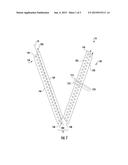
[0013] FIG. 1 illustrates an indoor coil, generally referenced at 10. The indoor coil 10 includes at least one coil slab 12, including a pair of coil slab end surfaces 14 extending between a pair of coil slab faces 16, and a coil slab axis 18, wherein one of the pair of coil slab end surfaces 14 forms an angle 20 greater than or equal to 45 degrees and less than 90 degrees with the coil slab axis 18. In at least one embodiment, the other of the pair of coil slab end surfaces 14 forms an angle 20 greater than or equal to 45 degrees and less than 90 degrees with the coil slab axis 18. Including an angle 20 greater than or equal to 45 degrees and less than 90 degrees with the coil slab axis may provide a narrower coil end surface 14; thus, lowering the internal pressure drop within a fan coil assembly, later described herein, by decreasing the width of a drain pan positioned to collect condensate from the indoor coil 10. Moreover, including an angle 20 greater than or equal to 45 degrees and less than 90 degrees with the coil slab axis 18 may also increase the space between the pair of coil slab faces 16; thus, increasing heat transfer convection by altering the air approach angle to the pair of coil slab faces 16. For example, coil slab end surfaces 14A and 14B may form respective angles 20A and 20B of 52 degrees with the coil slab axis 18. It will be appreciated that coil slab end surfaces 14A and 14B may form different angles 20 with the coil slab axis 18. The at least one coil slab 12 may be composed of copper or aluminum, and arranged in a tube and fin configuration to name just a few non-limiting examples. It will be appreciated that the at least one coil slab 12 may include any suitable number of rows of conduits, for example, two or three to name two non-limiting examples.
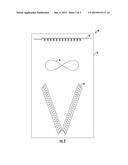
[0014] In at least one embodiment, at least one conduit 22 may be disposed within the at least one coil slab 12. The at least one conduit 22 being configured to allow a liquid, for example a refrigerant to name one-non-limiting example, to flow therethrough. In at least one embodiment, the at least one conduit 22 includes a plurality of conduits 22 operably coupled to one another. Including coil slab end surfaces 14, including an angle 20 greater than or equal to 45 degrees and less than 90 degrees with the coil slab axis 18, may reduce the number of connections between the plurality of conduits 22; thus, reducing the manufacturing cost of the indoor coil 10. In at least one embodiment, the plurality of conduits 22 may be arranged in a staggered configuration. Including a plurality of conduits 22 arranged in a staggered configuration may maintaining heat transfer performance, of the indoor coil 10, with a fewer quantity of conduits 22. For example, in a two row conduit configuration, a first row A of conduits 22A may be disposed within the at least one coil slab 12 from the coil slab end surface 14A to the coil slab end surface 14B, adjacent to the coil face 16A, and parallel to the coil slab axis 18. A second row B of conduits 22B may be disposed within the at least one coil slab 12 from the coil slab end surface 14A to the coil slab end surface 14B, adjacent to the coil face 16B, and parallel to the coil slab axis 18. Beginning from coil slab end surface 14A and moving towards coil slab end surface 14B, each of the conduits 22A include a leading edge 21A and each of the conduits 22B include a leading edge 22B. The leading edge 21A of one conduit 22A within row A may be either ahead of or behind the leading edge 22B of the adjacent conduit 22B within row B.
[0015] In at least one embodiment, the at least one coil slab 12 includes a first coil slab 12A and a second coil slab 12B. In at least one embodiment, the first coil slab 12A and the second coil slab 12B may be arranged in a "V" configuration. Including the first coil slab 12A and the second coil slab 12B, including an angle 20 greater than or equal to 45 degrees and less than 90 degrees with the coil slab axis 18, arranged in a "V" configuration may reduce the height of the indoor coil 10; thus, reducing the height of the fan coil assembly, later described herein. For example, a corner of the coil slab end surface 14B of the first coil slab 12A may be in close proximity to a corner of the coil slab end surface 14B of the second coil slab 12B to form an apex 15. It will be appreciated that the corner of the coil slab end surface 14B of first coil slab 12A may be in contact with the corner of the coil slab end surface 14B of the second coil slab 12B to form the apex 15. It will be appreciated that the first coil slab 12A and the second coil slab 12B may be arranged in an "A" configuration to name one non-limiting example. It will also be appreciated that the at least one coil slab 12 may be arranged in a "M", "N" and "W" configuration to name a few non-limiting examples.
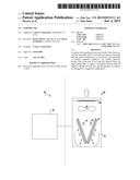
[0016] FIG. 2 illustrates a fan coil assembly, generally referenced at 30. The fan coil assembly 30 includes a cabinet 32, and an indoor coil 10 disposed within the cabinet. In at least one embodiment, the fan coil assembly 30 further includes a fan 34 disposed within the cabinet 30. The fan 34 being operable to circulate air across the indoor coil 10 and through the cabinet 32. It will be appreciated that there are many suitable types of fans 34 that may be used, such as, a centrifugal fan, radial fan, or an axial fan, to name a few non-limiting examples. In at least one embodiment, the fan coil assembly 30 further includes an auxiliary heating assembly 36 disposed within the cabinet 32. It will be appreciated that the auxiliary heating assembly 36 may be operably coupled to the cabinet 32. The auxiliary heating assembly 36 may be configured to provide supplemental heat to an interior space. For example, the auxiliary heating assembly 36 may be a nickel chromium conductive wire or a secondary heating coil configured to allow heater water to flow therethrough to name a couple of non-limiting examples.
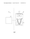
[0017] FIG. 3 illustrates an HVAC system, generally referenced at 40. The HVAC system 40 includes a heat pump 42 operably coupled to a fan coil assembly 30. The heat pump 42 may be configured to circulate a liquid, for example a refrigerant, therethrough. For example, as the heat pump 42 compresses the liquid and delivers the compressed liquid to the indoor coil 10 within the fan coil assembly 30, the fan 32 operates to circulate air 44 across the pair of coil slab end surfaces 14 each forming an angle 20 greater than or equal to 45 degrees and less than 90 degrees with the respective coil slab axis 18. It will also be appreciated that the fan coil assembly 30 may be operably coupled to a chiller configured to circulate chilled water.
[0018] It will be appreciated that the indoor coil 10 includes one of the pair of coil slab end surfaces 14 forming an angle 20, greater than or equal to 45 degrees and less than 90 degrees with the coil slab axis 18 to maintain performance, but reduce manufacturing cost by eliminating conduits that may not significantly contribute to heat exchange, decrease internal pressure drop, improve heat transfer convection, and reduce the overall height of the fan coil assembly 30.
[0019] While the invention has been illustrated and described in detail in the drawings and foregoing description, the same is to be considered as illustrative and not restrictive in character, it being understood that only certain embodiments have been shown and described and that all changes and modifications that come within the spirit of the invention are desired to be protected.
User Contributions:
Comment about this patent or add new information about this topic:
| People who visited this patent also read: | |
| Patent application number | Title |
|---|---|
| 20180128171 | METHOD AND APPARATUS FOR POWER STORAGE |
| 20180128170 | Spherical Compensator Junction Assembly for High Pressure Ducting System |
| 20180128169 | SIMPLIFIED ENGINE BLEED SUPPLY WITH LOW PRESSURE ENVIRONMENTAL CONTROL SYSTEM FOR AIRCRAFT |
| 20180128168 | GEARED TURBOFAN WITH THREE TURBINES ALL COUNTER-ROTATING |
| 20180128167 | COMPRESSED AIR ENERGY STORAGE AND POWER GENERATION METHOD AND COMPRESSED AIR ENERGY STORAGE AND POWER GENERATION DEVICE |
Images included with this patent application:
 |  |
 |  |
| New patent applications in this class: | |
| Date | Title |
|---|---|
| 2022-09-08 | Shrub rose plant named 'vlr003' |
| 2022-08-25 | Cherry tree named 'v84031' |
| 2022-08-25 | Miniature rose plant named 'poulty026' |
| 2022-08-25 | Information processing system and information processing method |
| 2022-08-25 | Data reassembly method and apparatus |
| New patent applications from these inventors: | |
| Date | Title |
|---|---|
| 2022-07-28 | Condensate block for v-coil heat exchanger |
| 2021-10-14 | Negative air filtration system |
| 2017-06-22 | Motor interface assembly and a method of using the same |
| 2015-12-03 | Acoustic treatment for an indoor hvac component |
| 2015-11-26 | Auxiliary heating assembly for use with residential air handlers |