Patent application title: Apparatus and Methods Related to Constrained Deployment of Cryogenic Balloons for Limited Cryogenic Abiation of Vessel Walls
Inventors:
Brian Kelly (Galway, IE)
Brian Kelly (Galway, IE)
John Kelly (Ballinsloe, IE)
Gary Kelly (Galway, IE)
Barry Mullins (Wicklow, IE)
Assignees:
Medtronic Ardian Luxembourg S.a.r.l.
IPC8 Class: AA61B1802FI
USPC Class:
606 24
Class name: With coolant supply tip or other cooling concentration means with heating means (e.g., defroster)
Publication date: 2015-05-07
Patent application number: 20150126986
Abstract:
Embodiments related to cryogenically ablating a portion of the inner
surface of a vessel by constraining a cryoballoon using various
apparatuses and methods are disclosed. For example, a catheter can
include a cryoballoon for ablation of the vessel wall and a constraining
element disposed substantially in parallel with the cryoballoon to
deflect or offset a portion of the cryoballoon away from non-target
tissue of the vessel wall and prevent ablation of the non-target tissue.
Partial circumferential, non-continuous, or helical ablation can be
effective for treating a variety of renal, cardio-renal, and other
diseases including but not limited to hypertension, heart failure, renal
disease, renal failure, contrast nephropathy, arrhythmia, and myocardial
infarction. The constraining element may be, for example, a second
inflatable balloon or one or more self-expanding prongs.Claims:
1. A cryotherapeutic device, comprising: an elongated shaft including a
distal portion, the shaft configured to locate the distal portion in an
anatomical vessel; a first balloon at the distal portion; a first supply
lumen along at least a portion of the shaft; a first exhaust lumen along
at least a portion of the shaft, the first exhaust lumen fluidly
connected to the first supply lumen via the first balloon; a second
balloon at the distal portion fluidly separate from the first supply
lumen and the first exhaust lumen, the second balloon configured to
prevent the first balloon from cryogenically cooling a full circumference
of a wall of the anatomical vessel in generally any plane perpendicular
to a length of the anatomical vessel; a second supply lumen along at
least a portion of the shaft; and a second exhaust lumen along at least a
portion of the shaft, the second exhaust lumen fluidly connected to the
second supply lumen via the second balloon.
2. The cryotherapeutic device of claim 1 wherein-- the first balloon is non-compliant or semi-compliant, and the second balloon is compliant.
3. The cryotherapeutic device of claim 1 wherein-- the first balloon is less than 10% compliant, and the second balloon is between 50% and 100% compliant.
4. The cryotherapeutic device of claim 1 wherein-- the second balloon includes a proximal portion and a distal portion, the second supply lumen includes an opening at one of the proximal and distal portions of the second balloon, and the second exhaust lumen includes an opening at the other of the proximal and distal portions of the second balloon.
5. The cryotherapeutic device of claim 1 wherein-- the cryotherapeutic device is configured to cryogenically cool a portion of the wall of the anatomical vessel proximate the first balloon when pressurized refrigerant is delivered to the first balloon through the first supply lumen, expanded in the first balloon, and exhausted from the first balloon through the first exhaust lumen, and the cryotherapeutic device is configured to warm the first balloon when a heat-transfer fluid is delivered to the second balloon through the second supply lumen, moved within the second balloon, and exhausted from the second balloon through the second exhaust lumen.
6. A method for treating a patient, comprising: locating a distal portion of an elongated shaft of a cryotherapeutic device within an anatomical vessel of the patient; delivering refrigerant to a first balloon of the cryotherapeutic device at the distal portion; expanding the refrigerant within the first balloon to cool the first balloon; cooling a portion of a wall of the anatomical vessel proximate the first balloon; and circulating a heat-transfer fluid through a second balloon of the cryotherapeutic device proximate the first balloon and fluidly separate from the first balloon to warm the first balloon and to moderate the cooling of the portion of the wall of the anatomical vessel.
7. The method of claim 6 wherein circulating the heat-transfer fluid causes a temperature of the first balloon to be between -10.degree. C. and -40.degree. C.
8. The method of claim 6 further comprising contacting between 45.degree. and 225.degree. of the wall of the anatomical vessel with the first balloon.
9. The method of claim 6 further comprising-- semi- or non-compliantly expanding the first balloon with the refrigerant; and compliantly expanding the second balloon with the heat-transfer fluid.
10. The method of claim 6 further comprising using the second balloon to prevent the first balloon from cryogenically cooling a full circumference of the wall of the anatomical vessel in generally any plane perpendicular to a length of the anatomical vessel.
11. A cryotherapeutic device, comprising: a first catheter, including-- a first elongated shaft having a distal portion, a first balloon at the distal portion of the first shaft, a supply lumen along at least a portion of the first shaft, an exhaust lumen along at least a portion of the first shaft, the exhaust lumen fluidly connected to the supply lumen via the first balloon; a second catheter, including-- a second elongated shaft having a distal portion, and a second balloon at the distal portion of the second shaft; and a coupler sleeve configured to be within an anatomical vessel and to receive the first and second catheters in a parallel arrangement.
12. The cryotherapeutic device of claim 11, further comprising a third catheter, wherein-- the third catheter includes-- a third elongated shaft having a distal portion, and a third balloon at the distal portion of the third shaft, the second balloon and the third balloon are configured to expand to different sizes, and the second and third catheters are interchangeable with respect to the coupler sleeve.
13. The cryotherapeutic device of claim 11 further comprising an expandable outer sheath connected to the coupler sleeve, wherein the first and second balloons are configured to fit together within the expandable outer sheath when the first and second catheters are within the coupler sleeve.
14. The cryotherapeutic device of claim 11 wherein the cryotherapeutic device is configured to cryogenically cool a portion of a wall of the anatomical vessel proximate the first balloon when pressurized refrigerant is delivered to the first balloon through the first supply lumen, expanded in the first balloon, and exhausted from the first balloon through the first exhaust lumen.
15. The cryotherapeutic device of claim 11 wherein the second balloon is configured to prevent the first balloon from cryogenically cooling a full circumference of the wall of the anatomical vessel in generally any plane perpendicular to a length of the anatomical vessel.
16. The cryotherapeutic device of claim 11 wherein-- the first catheter includes a first guidewire lumen along at least a portion of the first shaft and extending through the first balloon, and the second catheter includes a second guidewire lumen along at least a portion of the second shaft and extending through the second balloon.
17. A method for treating a patient, comprising: locating a distal portion of a first elongated shaft of a first catheter within an anatomical vessel of the patient; delivering refrigerant to a first balloon of the first catheter at the distal portion of the first shaft; expanding the refrigerant within the first balloon to cool the first balloon; cooling a portion of a wall of the anatomical vessel proximate the first balloon; selecting a second catheter from a plurality of catheters based on a size of the anatomical vessel and a size of a second balloon of the second catheter; locating a distal portion of a second elongated shaft of the second catheter within the anatomical vessel proximate the first distal portion of the first elongated shaft, the second balloon being at the distal portion of the second elongated shaft; and expanding the second balloon between the first balloon and the wall of the anatomical vessel to prevent the first balloon from cryogenically cooling a full circumference of the wall of the anatomical vessel in generally any plane perpendicular to a length of the anatomical vessel.
18. The method of claim 17 wherein locating the distal portion of the first shaft and locating the distal portion of the second shaft are generally simultaneous.
19. The method of claim 17 further comprising coupling the first and second catheters after selecting the second catheter.
20. The method of claim 19 wherein coupling the first and second catheters includes introducing the first and second catheters into a coupler sleeve.
21. A cryotherapeutic device, comprising: an elongated shaft including a distal portion, the shaft configured to locate the distal portion in an anatomical vessel; an elongated balloon at the distal portion; a supply lumen along at least a portion of the shaft; an exhaust lumen along at least a portion of the shaft, the exhaust lumen fluidly connected to the supply lumen via the balloon; and an elongated, self-expanding prong at the distal portion, wherein-- the balloon is configured to preferentially expand away from the prong, and the prong is configured to prevent the balloon from cryogenically cooling a full circumference of a wall of the anatomical vessel in generally any plane perpendicular to a length of the anatomical vessel.
22. The cryotherapeutic device of claim 21 wherein the balloon is non-compliant or semi-compliant.
23. The cryotherapeutic device of claim 21 wherein the balloon is less than 10% compliant.
24. The cryotherapeutic device of claim 21 wherein-- the prong is a first prong, the cryotherapeutic device further comprises a second prong, and the first and second prongs are deployable independently or together to change the size of a portion of the anatomical vessel cryogenically cooled by the balloon.
25. The cryotherapeutic device of claim 21 wherein-- the prong is a first prong, the cryotherapeutic device further comprises a second prong, and the first and second prongs are proximally connected to a push/pull wire.
26. The cryotherapeutic device of claim 25 wherein-- the first and second prongs are distally connected, and the cryotherapeutic device further comprises a diagonal support between the first and second prongs.
27. A method for treating a patient, comprising: locating a distal portion of an elongated shaft of a catheter within an anatomical vessel of the patient; pressing an elongated prong at the distal portion of the shaft against a first portion of a wall of the anatomical vessel, delivering refrigerant to a balloon of the catheter at the distal portion of the shaft to cool the balloon and to preferentially expand the balloon in a radial direction away from the prong; and cooling a second portion of the wall of the anatomical vessel proximate the balloon, wherein the prong urges the balloon against the second portion of the wall of the anatomical vessel and spaces the balloon apart from the first portion of the wall of the anatomical vessel.
28. The method of claim 27 wherein the first and second portions of the wall of the anatomical vessel are at generally opposite sides of the wall of the anatomical vessel.
29. The method of claim 27 wherein delivering refrigerant to the balloon non-compliantly or semi-compliantly expands the balloon.
30. The method of claim 27 further comprising controlling deflection of the prong to control the size of the second portion of the wall of the anatomical vessel.
31. The method of claim 27 further comprising selecting a number of elongated prongs at the distal portion of the shaft to press against the first portion of the wall of the anatomical vessel to control the size of the second portion of the wall of the anatomical vessel.
Description:
CROSS REFERENCE TO RELATED APPLICATION
[0001] This disclosure claims the benefit of U.S. Provisional Application No. 61/572,288, filed Apr. 25, 2011, which is incorporated herein by reference in its entirety.
TECHNICAL FIELD
[0002] The present technology relates in general to cryotherapy, and in particular, to apparatus and methods for cryogenically cooling a targeted area of an inner surface of an anatomical vessel or other tissue.
BACKGROUND
[0003] Cryotherapy can be a useful treatment modality in a wide range of catheter-based interventional procedures. For example, cryotherapeutic cooling can be used to modulate nerves or affect other tissue proximate anatomical vessels (e.g., blood vessels, other body lumens, or other areas in the body). This can reduce undesirable neural activity to achieve therapeutic benefits. Catheter-based neuromodulation utilizing cryotherapy can be used, for example, to modulate nerves and thereby reduce pain, local sympathetic activity, systemic sympathetic activity, associated pathologies, and other conditions. Furthermore, cryotherapy can be used, for example, for ablating tumors and treating stenosis. In some cryotherapeutic procedures, it can be useful to deliver cryotherapy via a balloon that can be expanded within an anatomical vessel. Such balloons can be operatively connected to extracorporeal support components (e.g., refrigerant supplies). As the applicability of cryotherapy for surgical intervention continues to expand, there is a need for innovation in the associated devices, systems, and methods. Such innovation has the potential to further expand the role of cryotherapy as a tool for improving the health of patients.
BRIEF DESCRIPTION OF THE DRAWINGS
[0004] Many aspects of the present disclosure can be better understood with reference to the following drawings. The components in the drawings are not necessarily to scale. Instead, emphasis is placed on illustrating clearly the principles of the present technology.
[0005] FIG. 1 is a partially schematic isometric detail view of a common location of neural fibers proximate an artery.
[0006] FIG. 2 is a partially schematic cross-sectional view of an artery having an ablation assembly deployed therein, wherein the ablation assembly includes a cryoballoon and a constraining element that can position the cryoballoon within the artery.
[0007] FIG. 2A is a partially schematic illustration of an ablation therapy pattern within an artery following treatment with the ablation assembly of FIG. 2.
[0008] FIG. 3 is a side view of a dual balloon catheter having an ablation assembly at the distal end thereof, wherein the dual balloon catheter includes a single guidewire lumen.
[0009] FIG. 3A is a cross-sectional view taken along line A-A of FIG. 3.
[0010] FIG. 3B is a cross-sectional view taken along line B-B of FIG. 3.
[0011] FIG. 3C is a sectional view taken along line C-C of FIG. 3.
[0012] FIG. 3D is a cross-sectional view taken along line D-D of FIG. 3.
[0013] FIG. 4 is a side view of a dual-balloon configuration of the ablation assembly of FIG. 3 according to another embodiment hereof.
[0014] FIG. 5 is a side view of a dual-balloon configuration of the ablation assembly of FIG. 3 according to another embodiment hereof.
[0015] FIG. 5A is a partially schematic cross-sectional view of an artery having the ablation assembly of FIG. 5 deployed therein.
[0016] FIG. 6 is a sectional view taken along line C-C of FIG. 3 according to another embodiment hereof, wherein the catheter further includes an inflation fluid retum shaft for circulating warm inflation fluid within the constraining element of the ablation assembly.
[0017] FIG. 7 is a sectional view taken along line C-C of FIG. 3 according to another embodiment hereof, wherein the catheter utilizes exhaust of the cryotherapy to inflate the constraining element of the ablation assembly.
[0018] FIG. 8 is a side view of a dual balloon catheter having an ablation assembly at the distal end thereof according to another embodiment hereof, wherein the dual balloon catheter includes two separate guidewire lumens.
[0019] FIG. 8A is a cross-sectional view taken along line A-A of FIG. 8.
[0020] FIG. 8B is a cross-sectional view taken along line B-B of FIG. 8.
[0021] FIG. 9 is a side view of a catheter assembly having an ablation assembly at the distal end thereof according to another embodiment hereof, wherein the catheter assembly includes two balloon catheters.
[0022] FIG. 9A is a cross-sectional view taken along line A-A of FIG. 9.
[0023] FIG. 9B is a cross-sectional view taken along line B-B of FIG. 9.
[0024] FIG. 10 is a side view of the distal portion of FIG. 8 or FIG. 9, wherein the two balloons are joined via an adhesive.
[0025] FIG. 11 is a side view of the distal portion of FIG. 8 or FIG. 9, wherein the two balloons are located within an outer sheath.
[0026] FIG. 12 is a partially schematic cross-sectional view of an artery having an ablation assembly according to another embodiment deployed therein, wherein the ablation assembly includes a cryoballoon and a constraining element that positions the cryoballoon within the artery.
[0027] FIG. 13 is a side view of a catheter having a ablation assembly at the distal end thereof according to another embodiment hereof, wherein the ablation assembly includes a cryoballoon and a pair of self-expanding prongs for deflecting at least a portion of the cryoballoon away from the vessel wall.
[0028] FIG. 13A is a side view of the distal portion of the catheter of FIG. 13, wherein the cryoballoon is in an expanded or inflated configuration and the prongs are constrained within a sheath.
[0029] FIG. 13B is a side view of the distal portion of the catheter of FIG. 13, wherein the cryoballoon is in an expanded or inflated configuration and the prongs are released from the sheath.
[0030] FIG. 13C is an illustrative perspective view of the distal portion of the catheter of FIG. 13 deployed within a vessel, wherein the cryoballoon is in an expanded or inflated configuration and the prongs are released from the sheath.
[0031] FIG. 14 is a side view of the prongs of FIG. 13, wherein the cryogenic balloon has been omitted for clarity and the prongs are in an expanded or deployed configuration.
[0032] FIG. 15 is a bottom view of the prongs of FIG. 13, wherein the cryogenic balloon has been omitted for clarity and the prongs are in an expanded or deployed configuration.
[0033] FIG. 16 is a side view of an alternative configuration of self-expanding prongs for deflecting at least a portion of the cryoballoon away from the vessel wall.
[0034] FIG. 17 is a side view of an alternative configuration of self-expanding prongs for deflecting at least a portion of the cryoballoon away from the vessel wall.
[0035] FIG. 18 is a side view of an alternative configuration of self-expanding prongs for deflecting at least a portion of the cryoballoon away from the vessel wall.
[0036] FIG. 19 is a side view of an alternative configuration of self-expanding prongs for deflecting at least a portion of the cryoballoon away from the vessel wall.
DETAILED DESCRIPTION
[0037] Specific embodiments of the present technology are now described with reference to the figures, wherein like reference numbers indicate identical or functionally similar elements. The terms "distal" and "proximal" are used in the following description with respect to a position or direction relative to the treating clinician. "Distal" and "distally" refer to positions distant from or in a direction away from the clinician. "Proximal" and "proximally" refer to positions near or in a direction toward the clinician.
[0038] The following detailed description discloses specific examples of the technology, but it is not intended to limit the present technology or the application and uses of the present technology. For example, although the description discloses the present technology in the context of treatment of blood vessels, such as renal arteries, the present technology may also be used in any other body passageways or tissues where it is deemed useful. Furthermore, there is no intention to be bound by any expressed or implied theory presented herein.
[0039] In recent years, ablation of tissue has been used to modulate neural fibers that contribute to renal function. Ablation may be accomplished in various ways, including delivery of radio frequency (RF) energy, other suitable heating energies, or cryotherapy. Modulation of renal nerves is expected to be useful in treating a variety of renal, cardio-renal, and other diseases including heart failure, renal disease, renal failure, hypertension, contrast nephropathy, arrhythmia, and myocardial infarction. Furthermore, renal neuromodulation is expected to reduce renal sympathetic nervous activity, which can increase removal of water and sodium from the body and return renin secretion to more normal levels. Normalized renin secretion can cause blood vessels supplying the kidneys to assume a steady state level of dilation and constriction corresponding to adequate renal blood flow.
[0040] In neuromodulation procedures, it may be desirable to perform circumferential ablation that extends continuously about a full 360° of the circumference of an anatomical vessel to positively affect a medical condition. For example, in the treatment of atrial fibrillation or other arrhythmia, a circumferential treatment may be achieved by forming a circumferential lesion that is continuous completely about a normal cross-section of the pulmonary vein to disrupt aberrant electrical signals. In the treatment of heart failure, a circumferential treatment may be achieved by forming a similar continuous circumferential lesion that is continuous completely about a normal cross-section of a renal artery to reduce renal sympathetic neural activity. However, in some cases, it can be desirable to reduce structural changes to a blood vessel and avoid a circumferential ablation lesion along a single radial plane or cross-section of a blood vessel. Partial circumferential, non-continuous, or helical ablation are expected to be effective to treat a variety of renal, cardio-renal, and other diseases including those listed herein with less structural changes to vessels than fully circumferential, continuous, and non-helical ablation.
[0041] FIG. 1 illustrates a common anatomical arrangement of neural structures relative to body lumens or vascular structures, typically arteries. Neural fibers N generally may extend longitudinally along a lengthwise or longitudinal dimension L of an artery A about a relatively small range of positions along the radial dimension r, often within the adventitia of the artery. The artery A has smooth muscle cells SMC that surround the arterial circumference and generally spiral around the angular dimension e of the artery, also within a relatively small range of positions along the radial dimension r. The smooth muscle cells SMC of the artery A accordingly have a lengthwise or longer dimension generally extending transverse (i.e., non-parallel) to the lengthwise dimension of the blood vessel.
[0042] Neuromodulation may be accomplished by ablating tissue through the use of an ablation catheter. As utilized herein, the term ablation includes the creation of scar tissue or a lesion that blocks or disrupts nerve conduction. In embodiments hereof, freezing temperatures or cryotherapy can be utilized to thermally damage or ablate target tissue of an artery to achieve neuromodulation of the target neural fibers. As compared to ablation lesions formed via radiofrequency energy, cryotherapy typically utilizes much less power to achieve neuromodulation. As described above, partial circumferential ablation (i.e., ablation extending around less than 360° of a vessel wall), non-continuous ablation, or helical ablation may be desirable in some cases. In order to form partial circumferential, non-continuous, or helical ablation lesions, cryotherapy can be focused on or constrained to target regions of tissue to be treated and non-target tissue can be protected from ablation (e.g., by deflecting or offsetting a portion of a cryoballoon away from the non-target tissue using the various apparatuses and methods described herein).
[0043] Turning now to FIG. 2, an ablation assembly 200 is shown deployed within an artery A. Ablation assembly 200 includes a cryoballoon 234 for neuromodulation of the target neural fibers and a constraining element 236 that offsets cryoballoon 234 within the artery A. As will be explained in more detail below, in various embodiments hereof, constraining element 236 can be a radially-expandable component that expands into contact with at least one of a portion of the exterior surface of cryoballoon 234 and a portion of the vessel wall to prevent cryoballoon 234 from contacting and ablating non-targeted tissue of the vessel wall. Stated another way, constraining element 236 can deflect away or block a portion of the surface of cryoballoon 234 from contacting non-targeted tissue of the vessel wall such that cryoballoon 234 will contact a section of the vessel wall that corresponds to less than a full circumference of the vessel wall and thereby perform a partial circumferential ablation of a longitudinal section of the vessel wall. As shown in FIG. 2, in one embodiment constraining element 236 is a second balloon which pushes away or blocks a portion of cryoballoon 234 from contacting non-target tissue of the vessel wall. Partial circumferential, non-continuous, or helical ablation of artery A can alter the sympathetic nervous system and can be effective for treating a variety of renal, cardio-renal, and other diseases including but not limited to hypertension, heart failure, renal disease, renal failure, contrast nephropathy, arrhythmia, and myocardial infarction.
[0044] A resulting cross-section of the ablation pattern or footprint of ablation assembly 200 is shown in FIG. 2A. The area of contact between the exterior surface of cryoballoon 234 and the vessel wall may be considered a nominal treatment area, which is equal to or slightly smaller than the ablation pattern resulting from ablation assembly 200 because the ablation therapy may extend slightly beyond the borders of the nominal treatment area. For example, the nominal treatment area of ablation assembly 200 may extend around between 45° and 225° of the vessel wall circumference while the resulting ablation pattern of ablation assembly 200 may extend around between 10° and 340° of the vessel wall circumference. However, for purposes of the present disclosure, the nominal treatment area and the ablation pattern are considered to be approximately equal. The nominal treatment area/ablation pattern depends upon both a contact surface arc O of the ablation assembly and a working length LW of cryoballoon 234 (see FIG. 3 and FIG. 4 for examples of working lengths LW of a cryoballoon). More particularly, the nominal treatment area/ablation pattern may be calculated by multiplying the length of the contact surface arc LO by the working length LW of cryoballoon 234. The length of contact surface arc may be roughly calculated by the equation LO=R((2 O)/360), wherein R is the radius and O is the contact surface arc. As previously mentioned, in embodiments hereof, constraining element 236 can deflect or offset cryoballoon 234 from contacting non-targeted tissue such that the contact surface arc O of cryoballoon 234 is constrained or limited to between 45° and 225° of the vessel wall.
[0045] The side view of FIG. 3 as well as the cross-sectional views FIG. 3A and FIG. 3B illustrate a first embodiment having an ablation assembly of a cryoballoon and a second balloon for deflecting the cryoballoon away from non-target tissue. More particularly, a dual balloon catheter 306 includes an ablation assembly 300 at a distal end thereof. Ablation assembly 300 includes a first cryoballoon 334 and a second constraining balloon 336 that are disposed substantially in parallel, i.e., side-by-side, such that at least a portion of the exterior or outer surfaces of cryoballoon 334 and constraining balloon 336 are in contact in their expanded configurations. Balloons 334, 336 are shown in their expanded or inflated configurations in FIG. 3. For illustrative purposes only, balloons 334, 336 as well as other dual balloon configurations described herein are shown in the figures as slightly separated from each other in their expanded configurations. However, it will be understood by those of ordinary skill in the art that at least a portion of the outer surfaces of balloons 334, 336 and all dual balloon configurations described herein typically press against and contact each other when deployed in a vessel and constrained by the vessel wall as shown in FIG. 2. Balloons 334, 336 and other balloons disclosed herein can be made using a variety of suitable manufacturing processes. For example, the balloons 334, 336 can be made using extrusion, molding, or a combination thereof. Furthermore, the balloons 334, 336 can be formed separately or together. In some embodiments, when the balloons 334, 336 are made of different materials (e.g., materials with different compliances), the different materials can be processed simultaneously (e.g., by coextrusion).
[0046] In the embodiment shown in FIGS. 3, 3A, and 3B, dual-balloon catheter 306 has an over-the-wire (OTW) catheter configuration with an inner guidewire shaft 320 that defines a guidewire lumen 322 extending substantially the entire length of the catheter for accommodating a guidewire 342. Catheter 306 includes a tubular component or outer shaft 316 which defines a lumen 318. Outer shaft 316 has a proximal end 340 that extends out of the patient and is coupled to a hub 308 and a distal end 341 coupled to proximal necks 315, 317 of balloons 334, 336, respectively. Distal necks 319, 321 of balloons 334, 336, respectively, are coupled to guidewire shaft 320. Proximal necks 315, 317 and distal necks 319, 321 of balloons 334, 336 may be joined to outer catheter shaft 316 and guidewire shaft 320, respectively, in any conventional manner known to one of skill in the art of balloon catheter construction, such as by laser welding, adhesives, heat fusing, or ultrasonic welding. In one embodiment, balloons 334, 336 are formed as two separate components, the ends of proximal necks 315, 317 are joined, and the ends of distal necks 319, 321 are joined. Other suitable manufacturing methods and configurations are also possible.
[0047] Guidewire shaft 320 has a proximal end (not shown) coupled to hub 308 and a distal end 338 terminating distally of balloons 334, 336. A proximal guidewire port 314 of hub 308 is in fluid communication with guidewire lumen 322 of guidewire shaft 320. Distal end 338 of guidewire shaft 320 may be coupled to a tapered distal catheter tip (not shown) that defines a distal guidewire port of the catheter. As shown in the sectional view of FIG. 3C, in one embodiment guidewire shaft 320 extends through cryoballoon 334. However, it will be apparent to those of ordinary skill in the art that catheter 306 may be modified such that guidewire shaft 320 alternatively extends through constraining balloon 336. A single guidewire lumen can simplify catheter construction and luer design, as well as reduce the outer diameter of catheter 306. In addition, since distal necks 319, 321 of balloons 334, 336, respectively, are both coupled to guidewire shaft 320, the single guidewire lumen catheter construction can help to maintain balloons 334, 336 in position relative to each other during deployment.
[0048] Catheter 306 further includes a cryo-supply tube 324 extending through outer shaft 316. The cryo-supply tube 324 defines an inflation lumen 326 (see FIGS. 3A-3B) and has a proximal end (not shown) coupled to hub 308 and a distal end 325 (see FIG. 3C) that terminates within cryoballoon 334. A cryo-inflation port 310 of hub 308 is in fluid communication with inflation lumen 326 of cryo-supply tube 324. Cryo-supply tube 324 receives and delivers a cryogenic agent such as N2O liquid into cryoballoon 334 at a high pressure, e.g., 800 psi, such that there is a pressure drop when the cryogenic agent enters the interior of cryoballoon 334 and expands to a gas. The cryogenic agent may be any liquid having a boiling point colder than approximately -10° C. at atmospheric pressure such as but not limited to N2O liquid or CO2 liquid. During the phase change of the cryogenic agent, a cooling effect takes place because expansion of compressed gas is an endothermic process that absorbs energy in the form of heat and thus results in cooling of the surroundings. Accordingly, as the cryogenic agent expands into gas, cryoballoon 334 is expanded or inflated and the exterior surface of the cryoballoon is cooled to cryogenic temperatures operable to ablate or thermally damage tissue. The temperature of cryoballoon 334 may be between approximately -5° C. and -120° C., which can result in modulation of neural fibers located adjacent to cryoballoon 334. As would be understood by one of ordinary skill in the art of balloon catheter design, hub 308 can provide a luer hub or other type of fitting that may be connected to a source of inflation fluid and may be of another construction or configuration without departing from the scope of the present technology.
[0049] Catheter 306 also includes a constraining-supply tube 328 extending through outer shaft 316. The constraining-supply tube 328 defines an inflation lumen 330 and has a proximal end (not shown) coupled to hub 308 and a distal end 327 (see FIG. 3C) that terminates within constraining balloon 336. An inflation port 312 of hub 308 is in fluid communication with inflation lumen 330 of constraining-supply tube 328. Constraining-supply tube 328 receives and delivers an inflation medium such as saline or air into constraining balloon 336. Once inflated, constraining balloon 336 prevents a portion of the outer surface of cryoballoon 334 from coming into contact with non-targeted tissue of the vessel wall. More particularly, constraining balloon 336 expands to push away or deflect a portion of the outer surface of cryoballoon 334 from contacting non-targeted tissue of the vessel wall. Non-targeted tissue may thereby be prevented from contact with or protected from the cryogenically-cooled exterior surface of cryoballoon 334, and therefore constraining balloon 336 may prevent a complete continuous circumferential ablation of the vessel wall.
[0050] In addition to offsetting cryoballoon 334, in one embodiment constraining balloon 336 also serves to moderate the temperature of the cryotherapy. For example, when N2O liquid is utilized as the cryogenic agent, the phase change of the cryogenic agent to gas may result in a cryoballoon temperature in the range of -70° C. to -80° C. However, neuromodulation may be accomplished at temperatures between -10° C. and -40° C., and these higher temperatures may be preferred in certain applications to minimize unnecessary damage to the vessel. Since cryoballoon 334 and constraining balloon 336 deploy and expand against each other within the artery during treatment, heat transfer can occur therebetween. Accordingly, an inflation fluid such as water or saline within constraining balloon 336 may freeze. However, the decrease in resulting temperature will not be to such an extent that thermal injury will occur. Thermal injury or neuromodulation generally occurs at temperatures below -5° C., while a frozen constraining balloon 336 can have a temperature at or above -3° C. Notably, the heat transfer from constraining balloon 336 to cryoballoon 334 may be beneficial to increase the temperature of the cryogenically-cooled balloon outer surface from, e.g., -80° C., to a preferred temperature for ablation, e.g., between -10° C. and -40° C. Thus, the heat transfer between the balloons may help to moderate the temperatures of the cryotherapy.
[0051] In one embodiment, balloons 334, 336 are inflated simultaneously. In another embodiment, constraining balloon 336 and cryoballoon 334 are inflated sequentially. Constraining balloon 336 may be inflated prior to cryoballoon 334 in order to properly position and/or orient the balloons within the artery.
[0052] The multiple catheter shafts of catheter 306, e.g., outer shaft 316, guidewire shaft 320, cryo-supply tube 324, and constraining-supply tube 328, may be formed of a polymeric material, non-exhaustive examples of which include polyethylene, polyethylene block amide copolymer (PEBA), polyamide, and/or combinations thereof, which can be laminated, blended, co-extruded, or processed according to another suitable method. In an embodiment, guidewire shaft 320 may be a flexible tube of a polymeric material, such as, e.g., polyethylene tubing. Optionally, outer shaft 316 or some portion thereof may be formed as a composite having a reinforcement material incorporated within a polymeric body in order to enhance strength and/or flexibility. Suitable reinforcement layers can include braiding, wire mesh layers, embedded axial wires, embedded helical or circumferential wires, and the like. In one embodiment, for example, at least a proximal portion of outer shaft 316 may be formed from a reinforced polymeric tube. In addition, although catheter 306 is described herein as being constructed with various shafts extending therethrough for forming lumens of the catheter, it will be understood by those of ordinary skill in the art that other types of catheter construction are also possible, such as, without limitation thereto, a catheter shaft formed by multi-lumen profile extrusion. In another embodiment, catheter 306 may be modified to be of a rapid exchange (RX) catheter configuration without departing from the scope of the present technology such that guidewire shaft 320 extends within only the distal portion of catheter 306.
[0053] Although shown as having approximately equal expanded profiles, the cryoballoon and the constraining balloon may have different, unequal dimensions depending on the desired ablation therapy pattern. For example, as shown in the embodiment of FIG. 4, an ablation assembly 400 can include a cryoballoon 434 which is shorter in length than a constraining balloon 436. As described above in more detail, the nominal treatment area/ablation pattern can depend upon the working length LW of the cryoballoon. Accordingly, in general, shorter cryoballoon 434 contacts less tissue in the longitudinal direction of the vessel wall than cryoballoon 334 and thus results in a smaller nominal treatment area than cryoballoon 334. In addition, shorter cryoballoon 434 may require a longer treatment time in order to achieve neuromodulation as opposed to longer cryoballoons which may cause deeper and/or longer ablation patterns.
[0054] In another example, the cryoballoon and the constraining balloon may have different expanded outer diameters. In the embodiment of FIG. 5, an ablation assembly 500 can include a cryoballoon 534 having a smaller expanded outer diameter than a constraining balloon 536. To achieve different expanded outer diameters, the balloons may be formed of materials having different compliances. Dilatation balloons may be classified, for example, as being compliant, noncompliant, or semi-compliant. Compliant balloons can be characterized by their ability to radially expand beyond their nominal diameters in response to increasing inflation pressure. Such balloons can be said to follow a stress-strain curve obtained by plotting balloon diameter versus inflation pressure. Noncompliant balloons can be characterized by nearly flat stress-strain curves illustrating that the balloon diameters expand relatively little over the range of usable inflation pressures. To achieve a smaller expanded outer diameter, cryoballoon 534 may be semi-compliant or non-compliant. In some embodiments, cryoballoon 534 can be 10% or less compliant and formed from PEBAX polymer or nylon. Constraining balloon 536 may be, for example, between 50% and 100% compliant and formed from polyurethane or silicone. Percentage compliance can correspond to the percentage of expansion that occurs between the cryoballoon 534 at an operating pressure and the cryoballoon 534 at a rated pressure (e.g., a burst pressure or a maximum inflation pressure). The recited values for percentage compliance can also apply to dispensability, which can be calculated as follows:
Distensibility = [ Diameter of Balloon at Selected Pressure Nominal Diameter of Balloon - 1 ] × 100 % ##EQU00001##
The selected pressure can be an arbitrary, relatively high pressure (e.g., 10 bar). Suitable materials that may be utilized to achieve a desired amount of compliance for the balloons include but are not limited to polymers such as polyethylene, polyethylene block amide copolymer (PEBA), PEBAX polymer, nylon, silicone, polyethylene terephthalate (PET), polyamide, polyurethane, and copolymers or blends thereof.
[0055] As shown in FIG. 5A, during deployment within artery A, constraining balloon 536 of a greater expanded outer diameter can essentially wrap or curl around smaller cryoballoon 534, thereby preventing ablation of a greater circumferential portion of the vessel wall. Stated another way, the constraining balloon 536 can curl around smaller cryoballoon 534 and effectively reduce the contact surface arc O of the nominal treatment area/ablation pattern. The expanded diameter of cryoballoon 534 determines the contact surface arc O and therefore determines the amount of circumferential tissue cryogenically ablated. In general, smaller cryoballoon 534 contacts less tissue around the circumference of the vessel wall and thus results in a smaller nominal treatment area/ablation pattern than cryoballoon 334. In the embodiment depicted in FIG. 5A, contact surface arc O is less than half of the circumference of the vessel wall or between 45° and 180° of the vessel wall. In another embodiment (not shown), if it is desired to ablate more than half of the circumference of the vessel wall, the cryogenic balloon can have a contact surface arc O between 180° and 225° of the vessel wall and may be constructed to have a greater expanded outer diameter than the constraining balloon such that the larger cryoballoon wraps around the smaller constraining balloon during deployment.
[0056] Referring back to FIG. 3 as well as the sectional views of FIG. 3B, FIG. 3C, and FIG. 3D, another feature of catheter 306 is described. In the embodiment of FIG. 3, constraining balloon 336 can be inflated and held at a constant pressure or at a constant outer diameter depending on the design thereof and an interior of constraining balloon 336 is not in fluid communication with lumen 318 of outer shaft 316. As shown in the cross-sectional view of FIG. 3B which is taken at the location of a proximal bond 329 between balloon necks 315, 317 of balloons 334, 336, respectively, proximal bond 329 surrounds and seals off constraining-supply tube 328 from lumen 318 of outer shaft 316. At the site of proximal bond 329, outer shaft 316 transforms from the annular configuration of FIG. 3A to a generally figure "8" configuration which resembles balloon necks 315, 317. In one embodiment, proximal balloon neck 315 of cryoballoon 334 has a larger diameter and corresponding lumen than proximal balloon neck 317 of constraining balloon 336 in order to allow expanded cryogenic gas or exhaust to exit from the interior of cryoballoon 334 as will be explained in more detail herein. Although proximal balloon neck 315 may be larger than proximal balloon neck 317, the expanded outer diameters of balloons 334, 336 may be the same or different as described above. Proximal bond 329 may be formed in any suitable manner known in the art, including via an adhesive and/or heat fuse.
[0057] In contrast to constraining-supply tube 328, cryo-supply tube 324 and guidewire shaft 320 extend freely through, e.g., are not bonded to, outer shaft 316 and into balloon neck 315 of cryoballoon 334. As noted above and with reference to FIG. 3C, a continuous supply of cryofluid exits distal end 325 of cryo-supply tube 324 into the interior of cryoballoon 334 to expand therein. Concurrently, the expanded cryogenic gas proximally exits the interior of cryoballoon 334 via a space between shafts 324, 320 and outer shaft 316, as best shown in FIG. 3C. In an embodiment, a vacuum may be utilized to pull the expanded cryogenic gas out of the catheter although the vacuum is not required for the gas to exit. The expanded cryogenic gas travels proximally through proximal balloon neck 315 and within lumen 318 of outer shaft 316 for the length of catheter 306, and then exits catheter 306 via an arm 309 of hub 308. As shown in the cross-sectional view of FIG. 3D, cryotherapy shaft 324 extends freely through, e.g., is not bonded to, arm 309 and thus the expanded cryogenic gas may escape via an annular lumen or space 311 defined between cryotherapy shaft 324 and arm 309. In another embodiment (not shown), cryotherapy shaft 324 may be bonded or otherwise coupled to one sidewall of outer shaft 316.
[0058] FIG. 6 illustrates another embodiment hereof in which the inflation fluid for the constraining balloon may be circulated in order to better control the temperature thereof. More particularly, an ablation assembly 600 includes a cryoballoon 634 and a constraining balloon 636. Cryo-supply tube 624 and guidewire shaft 620 extend through outer shaft 616 and into proximal balloon neck 615 of cryoballoon 634 as described above with respect to catheter 306. However, in this embodiment, constraining-supply tube 628 as well as an inflation fluid return or exhaust shaft 650 extend through outer shaft 616 and into an interior of constraining balloon 636 via proximal balloon neck 617 of constraining balloon 636. Proximal bond 629 surrounds shafts 628, 650 and seals off the interior of constraining balloon 636 from lumen 618 of outer shaft 616. A continuous supply of inflation fluid enters the interior of constraining balloon 636 via constraining-supply tube 628 to inflate and expand constraining balloon 636. The inflation fluid then exits the interior of constraining balloon 636 via exhaust shaft 650 such that the inflation fluid within constraining balloon 636 may be continuously circulated. The continuous circulation allows for the inflation fluid within the interior of constraining balloon 636 to be maintained at a warmer temperature, which improves the ability of constraining balloon 636 to protect non-targeted tissue from ablation because constraining balloon 636 is prevented from cooling to a cryoablation temperature due to heat transfer with cryoballoon 634. The relatively warmer temperature maintained in constraining balloon 636 due to the continuous circulation of inflation fluid also permits improved heat transfer from constraining balloon 636 to cryoballoon 634 to better moderate the temperature of the cryotherapy as described herein.
[0059] FIG. 7 illustrates another embodiment hereof in which exhaust from the cryoballoon serves as the inflation fluid for the constraining balloon in order to simplify the construction of the catheter and reduce the required number of lumens, which may also reduce an outer diameter of the catheter. More particularly, an ablation assembly 700 can include a cryoballoon 734 and a constraining balloon 736. Cryo-supply tube 724 and guidewire shaft 720 extend through outer shaft 716 and into proximal balloon neck 715 of cryoballoon 734 as described above with respect to catheter 306. However, in this embodiment, a U-shaped connector 752 fluidly connects the interior of cryoballoon 734 and the interior of constraining balloon 736. The cryogenic agent is delivered into cryoballoon 734 and there is a pressure drop when the cryogenic agent enters the interior of cryoballoon 734 and expands to gas. As the cryogenic agent expands into gas, cryoballoon 734 is expanded and the exhaust gas travels through U-shaped connector 752 and into constraining balloon 736 to expand the constraining balloon. Although the temperature of cryoballoon 734 ablates target tissue in contact with cryoballoon 734, the exhaust gas that leaves cryoballoon 734 and fills constraining balloon 736 can be approximately 20° C. to 50° C. warmer than the temperature of cryoballoon 734. Thus, although the gas exhaust is still cool, the temperature of constraining balloon 736 can remain above -5° C. such that thermal injury of non-targeted tissue adjacent to constraining balloon 736 will not occur. In one embodiment (not shown), the length of U-shaped connector 752 may be increased such that the distal loop extends further distally into blood flow that serves to additionally warm the exhaust gas before it enters the interior of constraining balloon 736. The exhaust gas continues to flow through proximal neck 717 of constraining balloon 736, past proximal bond 729, and proximally exits the catheter through an unsealed arm of the hub in the same way as described above with respect to FIG. 3D.
[0060] In another embodiment hereof, the catheter may include two separate guidewire lumens for more controlled positioning of the ablation assembly. Two separate guidewire lumens also allow for two different types of guidewires to be utilized for placement of the catheter. For example, a floppy-tipped guidewire and a stiff-tipped guidewire may both be useful in advancing the catheter through tortuous anatomy. Although only one guidewire is required for positioning the catheter, both guidewires are in place and may be utilized if required. For example, as shown in FIG. 8, FIG. 8A, and FIG. 8B, a dual balloon catheter 806 includes an ablation assembly 800 at a distal end thereof. Ablation assembly 800 includes a cryoballoon 834 and a constraining balloon 836 disposed adjacent, i.e., side-by-side, to cryoballoon 834. A cryo-supply tube 824 and a guidewire shaft 820A extend through an outer shaft 816 and into a proximal balloon neck 815 of cryoballoon 834, in the manner described above with respect to catheter 306. Outer shaft 816 defines a lumen 818 therethrough.
[0061] Guidewire shaft 820A defines a guidewire lumen 822A for receiving a guidewire 842A. However in this embodiment, in addition to a constraining-supply tube 828 defining an inflation lumen 830, a second inner guidewire shaft 820B extends through constraining balloon 836. Guidewire shaft 820B defines a guidewire lumen 822B extending substantially the entire length of the catheter for accommodating a second guidewire 842B. Outer shaft 816 has a proximal end 840 that extends out of the patient and is coupled to a hub 808 and a distal end 841 coupled to proximal necks 815, 817 of balloons 834, 836, respectively. Distal ends 819, 821 of balloons 834, 836, respectively, are coupled to guidewire shafts 820A, 820B, respectively. Guidewire shafts 820A, 820B have proximal ends (not shown) coupled to hub 808 and distal ends that terminate distally of balloons 834, 836. Hub 808 includes guidewire port 814A in fluid communication with guidewire lumen 822A of guidewire shaft 820A and a guidewire port 814B in fluid communication with guidewire lumen 822B of guidewire shaft 820B. In addition, hub 808 includes a first inflation port 812 in fluid communication with inflation lumen 830 of constraining-supply tube 828 and a second inflation port 810 in fluid communication with inflation lumen 826 of cryo-supply tube 824. Similar to proximal bond 329 described above, a proximal bond 829 surrounds and seals off an interior of balloon 834 from lumen 818 of outer shaft 816. At the site of proximal bond 829, outer shaft 816 transforms from the annular configuration of FIG. 8A to a generally figure "8" configuration which resembles balloon necks 815, 817.
[0062] FIG. 9, FIG. 9A, and FIG. 9B illustrate another embodiment hereof in which the catheter may include two separate guidewire lumens for more controlled positioning of the ablation assembly. In this embodiment, two individual balloon catheters 906A, 906B are coupled together via a coupler sleeve 960. An ablation assembly 900 is formed at the distal end of balloon catheters 906A, 908B, with a cryoballoon 934 disposed at the distal end of balloon catheter 906A and a constraining balloon 936 disposed at the distal end of balloon catheter 906B. The first balloon catheter 906A includes an outer shaft 916A defining a lumen 918A. A cryo-supply tube 924 defining a lumen 926 and a guidewire shaft 920A defining a guidewire lumen 922A for receiving a guidewire 942A both extend through outer shaft 916A. Cryoballoon 934 disposed at the distal end of catheter 906A is inflated with a cryogenic agent as described above with respect to cryoballoon 334. The second balloon catheter 906B includes an outer shaft 916B and an inner guidewire shaft 920B defining a guidewire lumen 922B for receiving a guidewire 942B. In the coaxial catheter construction of second balloon catheter 906B, guidewire shaft 920B extends within outer shaft 916B such that an annular inflation lumen 918B is defined between an inner surface of outer shaft 916B and an outer surface of guidewire shaft 920B. Constraining balloon 936 disposed at the distal end of catheter 906B is inflated via inflation fluid delivered through annular inflation lumen 918B. A first hub 908A is coupled to first balloon catheter 906A and a second hub 908B is coupled to second balloon catheter 906B. Hubs 908A, 908B include guidewire ports 914A, 914B, respectively, in fluid communication with guidewire lumens 922A, 922B of guidewire shafts 920A, 920B and inflation ports 910, 912 in fluid communication with inflation lumens 926, 918B of cryo-supply tube 924 and outer shaft 916B, respectively. In this embodiment, having two separate balloon catheters may simplify the bond area between each catheter and its respective balloon since each outer shaft is bonded to a single proximal balloon neck rather than two bifurcating proximal balloon necks as described with respect to embodiments described above.
[0063] Coupler sleeve 960 extends over a portion of catheters 916A, 916B to couple them together and properly position balloons 934, 936 in parallel within a target artery. In an embodiment, coupler sleeve 960 has a length between 10 mm and 30 mm long. Coupler sleeve 960 may be formed from any suitable biocompatible material, including but not limited to polyethylene, polyethylene block amide copolymer (PEBA), polyamide, and/or combinations thereof, which can be laminated, blended, co-extruded, or processed according to another suitable method. Coupler sleeve 960 may have a circular or oval cross-section as shown in FIG. 9B, or may have a profile resembling the figure "8" to reduce the profile thereof. In an embodiment, coupler sleeve 960 may be a removable separate component and an operator may assemble separate balloon catheters 906A, 906B into coupler sleeve 960. As a result, the operator may select appropriate balloon sizes or types to best treat the treatment site. For example, the operator may select a catheter having a constraining balloon with a particular expanded outer diameter and/or length in order to customize the size of the nominal treatment area/ablation pattern. Such customization is useful for accommodating individual anatomy of a patient. In another embodiment, coupler sleeve 960 and balloon catheters 906A, 906B may be formed as a single, integral assembly.
[0064] In the embodiments of FIG. 8 and FIG. 9, the distal ends of the cryoballoon and the constraining balloon separately extend in a distal direction and are not joined together. As such, in one embodiment, one or more mechanisms may be utilized to couple the cryoballoon and the constraining balloon together, which may prevent the balloons from folding over one another during deployment. Referring to FIG. 10, in one embodiment, cryoballoon 834/934 and constraining balloon 836/936 are coupled together via an adhesive 1062. In another embodiment shown in FIG. 11, an outer sheath 1164 may be used to hold cryoballoon 834/934 and constraining balloon 836/936 adjacent to one another in a side-by-side configuration during deployment. In one embodiment, outer sheath 1164 is an elastic tubular member which expands as the cryoballoon and the constraining balloon are inflated. Outer sheath 1164 surrounds and constrains the cryoballoon and the constraining balloon to keep them in an adjacent or side-by-side configuration. Outer sheath 1164 is formed of a substantially noninsulative material which does not affect ablation performed by the cryoballoon, such as polyurethane, PEBAX polymer, or silicone. In another embodiment, outer sheath 1164 is not elastic. In yet another embodiment, outer sheath 1164 may comprise one or more annular segments (not shown) rather than a continuous tubular member that covers at least a portion of the cryoballoon and the constraining balloon.
[0065] In yet another embodiment, outer sheath 1164 may be closed at the distal end thereof in order to form an outer inflatable balloon which surrounds and constrains cryoballoon 834/934 and constraining balloon 836/936. In addition to keeping cryoballoon 834/934 and constraining balloon 836/936 in an adjacent side-by-side or generally parallel configuration, outer sheath 1164 can occlude blood flow when inflated against the vessel wall. Occlusion of blood flow may be desirable since blood flow past a cryogenic balloon may affect the desired ablation therapy pattern.
[0066] In another embodiment hereof, the ablation assembly includes one or more prongs for deflecting the cryogenic balloon away from non-target tissue within a vessel. More particularly, FIG. 12 is a partially schematic cross-sectional view of an artery A having an ablation assembly 1200 deployed therein. Ablation assembly 1200 includes a cryogenic balloon 1234 for ablating tissue and a constraining element 1236 that positions cryogenic balloon 1234 within the artery. In this embodiment, constraining element 1236 is a pair of self-expanding prongs that deflect or offset contact of cryoballoon 1234 against the vessel wall.
[0067] FIG. 13 is a side view of an example of a catheter system for delivering the self-expanding prongs that deflect a cryoballoon away from non-target tissue of the vessel wall. More particularly, a balloon catheter 1306 includes an outer shaft 1316 defining a lumen (not shown) and an inner guidewire shaft 1320 defining a guidewire lumen (not shown) for receiving a guidewire 1342. In the catheter construction of balloon catheter 1306, a cryogenic inflation shaft (not shown in FIG. 13) similar to cryo-supply tube 324 extends through catheter 1306 for receiving a cryogenic inflation medium to inflate cryogenic balloon 1334. Cryoballoon 1334 is inflated with a cryogenic agent as described above with respect to cryoballoon 334, and expanded cryogenic gas or exhaust exits catheter 1306 via the space defined between an inner surface of outer shaft 1316 and the outer surfaces of guidewire shaft 1320 and the cryogenic inflation shaft. A hub 1308 is disposed at the proximal end of catheter 1306. Hub 1308 includes an inflation port 1310 in fluid communication with the inflation lumen of the cryogenic inflation shaft and a guidewire port 1314 in fluid communication with the guidewire lumen of inner guidewire shaft 1320. An ablation assembly 1300 includes a cryoballoon 1334 and a pair of self-expanding prongs 1372A, 1372B disposed at the distal end of catheter 1306. Only one of the prongs 1372A, 1372B is shown in FIG. 13 and in FIGS. 13A, 13B, and 14, which are described below.
[0068] As shown in FIG. 13A, a tubular sheath 1370 is disposed over catheter 1306 (FIG. 13) and constrains the pair of self-expanding prongs 1372A, 1372B into a reduced diameter suitable for delivery within a vasculature. Prongs 1372A, 1372B are coupled to a push-pull wire 1378 (FIG. 13), which proximally extends out of catheter 1306 and can be manipulated by the operator. Push-pull wire 1378 is utilized for distally advancing and proximally retracting prongs 1372A, 1372B within sheath 1370. When distally advanced out of sheath 1370, prongs 1372A, 1372B deploy to an expanded configuration shown in FIG. 13, FIG. 13B, FIG. 13C, FIG. 14, and FIG. 15. For clarity purposes, cryoballoon 1334 is omitted from the side view and bottom/top view of FIG. 14 and FIG. 15, respectively. Cryoballoon 1334 is pushed to one side of a vessel by prongs 1372A, 1372B which press against the opposite side of the artery to result in a partial circumferential ablation pattern. Cryoballoon 1334 is formed from a non-compliant or low-compliant material to prevent it from expanding between prongs 1372A, 1372B and onto the vessel wall. For example, cryoballoon 1334 may be formed from nylon, PEBAX polymer, or polyethylene terephthalate (PET).
[0069] Referring to FIG. 14 and FIG. 15, each prong 1372A, 1372B includes a proximal segment 1376A, 1376B, a curved segment 1374A, 1374B, and a distal segment 1380A, 1380B. In one embodiment, each prong 1372A, 1372B is a unitary structure formed out of a single or integral piece of material. In another embodiment, the curved segment 1374A, 1374B of each prong is a separate component which may be the same material or a different material that is attached to the proximal and distal segments by any suitable manner known in the art such as for example welding, including resistance welding, friction welding, laser welding or another form of welding, soldering, using an adhesive, adding a connecting element there between, or by another mechanical method. Prongs 1372A, 1372B can be formed from shape memory materials such as a nitinol wire, and can be self-expanding. The nitinol wire may be solid or hollow and may have a circular, oval, square, rectangular, or any other suitable cross-sectional shape.
[0070] During delivery, each prong 1372A, 1372B is constrained into a substantially straight configuration within sheath 1370 and when released from sheath 1370, each prong 1372A, 1372B assumes its preformed shape or deployed configuration that presses the outer surface of the balloon against the opposing vessel wall. More particularly, in the deployed configuration, proximal segments 1376A, 1376B are relatively short and substantially straight segments that distally extend from push-pull wire 1378. As shown in the bottom view of FIG. 15, proximal segments 1376A, 1376B diverge in opposing radial directions to place prongs 1372A, 1372B on opposing sides of cryogenic balloon 1334. As shown in the side view of FIG. 14, proximal segments 1376A, 1376B extend within a plane parallel to the longitudinal axis of the vessel. Curved segments 1374A, 1374B distally extend from proximal segments 1376A, 1376B and curve in a radial direction towards the vessel wall. Curved segments 1374A, 1374B operate to contact and push against the proximal portion of cryogenic balloon 1334 to deflect a portion of cryogenic balloon 1334 away from the vessel wall. Generally straight distal segments 1380A, 1380B distally extend from curved segments 1374A, 1374B in a direction parallel to the longitudinal axis of the vessel. Distal segments 1380A, 1380B press and/or lodge prongs 1372A, 1372B against one side of a vessel, while cryogenic balloon 1334 presses against the opposing side of the vessel.
[0071] In other embodiments, different configurations of self-expanding prongs that deflect cryogenic balloon 1334 away from non-targeted tissue of the vessel wall can be used. For example, FIG. 16 shows prongs 1672A, 1672B having distal ends that are connected via a V-shaped joining segment 1682, and FIG. 17 shows prongs 1772A, 1772B having distal ends that are connected with a rounded U-shaped joining segment 1782. Joining segments 1682, 1782 may be integrally formed between the two prongs, or may be a separate component coupled to the two prongs. Connecting the distal ends of the prongs can essentially form a single prong with improved stability for deflecting a cryoballoon. Prongs 1872A, 1872B in FIG. 18 are similar to prongs 1672A, 1672B but also include a diagonal support segment 1884 extending therebetween for stabilizing and/or strengthening the deflecting prong. Lastly, it will be understood by those of ordinary skill in the art that alternative deployment mechanisms may be utilized for deploying the deflecting prongs. For example, referring to FIG. 19, each prong 1972A, 1972B may be coupled to a separate push-pull wire 1978A, 1978B for individually controlling deployment of each prong. Separate deployment of each prong 1972A, 1972B provides selective control over the amount of the cryoballoon that is deflected away from the vessel wall, and therefore provides selective control over the ablation therapy pattern. For example, only one of prongs 1972A, 1972B may be deployed for less constraining of the cryoballoon and thus ablation occurring around a greater portion of the circumference of the vessel while both prongs 1972A, 1972B may be deployed for more constraining of the cryoballoon and thus ablation occurring around a lesser portion of the circumference of the vessel. In another embodiment, the deployment of self-expanding prongs may be accomplished and/or assisted by retraction of sheath 1370 as will be understood by those of ordinary skill in the art.
[0072] Since blood flow past a cryogenic balloon may affect the desired ablation therapy pattern, any embodiment described herein may include an occlusion balloon or other occlusive device. The occlusive device may be placed concentrically around the ablation assembly as described with respect to the outer sheath of FIG. 11, or may be placed proximal to or distal to the ablation assembly. Further, the occlusive device may be integrally formed on the delivery catheter of the ablation assembly or may be a separate device utilized with the delivery catheter of the ablation assembly.
[0073] Some embodiments are described herein with respect to partial circumferential ablation of vessel walls. However, in some applications, it may be desirable to perform full circumferential ablation of vessel walls that is also non-continuous or helical. Non-continuous, full circumferential ablation can include forming two or more partial circumferential ablations that collectively extend around the entire circumference of the vessel wall. Helical, full circumferential ablation can include forming one or more ablations that curve to extend around the entire circumference of the vessel wall without being fully circumferential in any single plane perpendicular to the vessel. The non-continuous or helical nature of these full circumferential ablations can reduce structural changes to any one region of the vessels in comparison to other full circumferential ablations. It will be understood by those of ordinary skill in the art that embodiments hereof for creating partial circumferential ablation patterns may also be utilized for creating non-continuous or helical full circumferential ablation patterns. For example, catheters having ablation assemblies described herein may be longitudinally translated within a vessel and rotated as desired in order to perform multiple, sequential partial circumferential ablations which collectively extend around the entire circumference of the vessel wall. In some embodiments, relatively short balloons having lengths between 2 mm and 5 mm may be rotated and moved longitudinally in a vessel to produce a non-continuous and helical ablation pattern.
EXAMPLES
[0074] 1. A cryotherapeutic device, comprising:
[0075] an elongated shaft including a distal portion, the shaft configured to locate the distal portion in an anatomical vessel;
[0076] a first balloon at the distal portion;
[0077] a first supply lumen along at least a portion of the shaft;
[0078] a first exhaust lumen along at least a portion of the shaft, the first exhaust lumen fluidly connected to the first supply lumen via the first balloon;
[0079] a second balloon at the distal portion fluidly separate from the first supply lumen and the first exhaust lumen, the second balloon configured to prevent the first balloon from cryogenically cooling a full circumference of a wall of the anatomical vessel in generally any plane perpendicular to a length of the anatomical vessel;
[0080] a second supply lumen along at least a portion of the shaft; and
[0081] a second exhaust lumen along at least a portion of the shaft, the second exhaust lumen fluidly connected to the second supply lumen via the second balloon.
[0082] 2. The cryotherapeutic device of example 1 wherein--
[0083] the first balloon is non-compliant or semi-compliant, and
[0084] the second balloon is compliant.
[0085] 3. The cryotherapeutic device of example 1 wherein--
[0086] the first balloon is less than 10% compliant, and
[0087] the second balloon is between 50% and 100% compliant.
[0088] 4. The cryotherapeutic device of example 1 wherein--
[0089] the second balloon includes a proximal portion and a distal portion,
[0090] the second supply lumen includes an opening at one of the proximal and distal portions of the second balloon, and
[0091] the second exhaust lumen includes an opening at the other of the proximal and distal portions of the second balloon.
[0092] 5. The cryotherapeutic device of example 1 wherein--
[0093] the cryotherapeutic device is configured to cryogenically cool a portion of the wall of the anatomical vessel proximate the first balloon when pressurized refrigerant is delivered to the first balloon through the first supply lumen, expanded in the first balloon, and exhausted from the first balloon through the first exhaust lumen, and
[0094] the cryotherapeutic device is configured to warm the first balloon when a heat-transfer fluid is delivered to the second balloon through the second supply lumen, moved within the second balloon, and exhausted from the second balloon through the second exhaust lumen.
[0095] 6. A method for treating a patient, comprising:
[0096] locating a distal portion of an elongated shaft of a cryotherapeutic device within an anatomical vessel of the patient;
[0097] delivering refrigerant to a first balloon of the cryotherapeutic device at the distal portion;
[0098] expanding the refrigerant within the first balloon to cool the first balloon;
[0099] cooling a portion of a wall of the anatomical vessel proximate the first balloon; and
[0100] circulating a heat-transfer fluid through a second balloon of the cryotherapeutic device proximate the first balloon and fluidly separate from the first balloon to warm the first balloon and to moderate the cooling of the portion of the wall of the anatomical vessel.
[0101] 7. The method of example 6 wherein circulating the heat-transfer fluid causes a temperature of the first balloon to be between -10° C. and -40° C.
[0102] 8. The method of example 6 further comprising contacting between 45° and 225° of the wall of the anatomical vessel with the first balloon.
[0103] 9. The method of example 6 further comprising--
[0104] semi- or non-compliantly expanding the first balloon with the refrigerant; and
[0105] compliantly expanding the second balloon with the heat-transfer fluid.
[0106] 10. The method of example 6 further comprising using the second balloon to prevent the first balloon from cryogenically cooling a full circumference of the wall of the anatomical vessel in generally any plane perpendicular to a length of the anatomical vessel.
[0107] 11. A cryotherapeutic device, comprising:
[0108] a first catheter, including--
[0109] a first elongated shaft having a distal portion,
[0110] a first balloon at the distal portion of the first shaft,
[0111] a supply lumen along at least a portion of the first shaft,
[0112] an exhaust lumen along at least a portion of the first shaft, the exhaust lumen fluidly connected to the supply lumen via the first balloon;
[0113] a second catheter, including--
[0114] a second elongated shaft having a distal portion, and
[0115] a second balloon at the distal portion of the second shaft; and
[0116] a coupler sleeve configured to be within an anatomical vessel and to receive the first and second catheters in a parallel arrangement.
[0117] 12. The cryotherapeutic device of example 11, further comprising a third catheter, wherein--
[0118] the third catheter includes--
[0119] a third elongated shaft having a distal portion, and
[0120] a third balloon at the distal portion of the third shaft,
[0121] the second balloon and the third balloon are configured to expand to different sizes, and
[0122] the second and third catheters are interchangeable with respect to the coupler sleeve.
[0123] 13. The cryotherapeutic device of example 11 further comprising an expandable outer sheath connected to the coupler sleeve, wherein the first and second balloons are configured to fit together within the expandable outer sheath when the first and second catheters are within the coupler sleeve.
[0124] 14. The cryotherapeutic device of example 11 wherein the cryotherapeutic device is configured to cryogenically cool a portion of a wall of the anatomical vessel proximate the first balloon when pressurized refrigerant is delivered to the first balloon through the first supply lumen, expanded in the first balloon, and exhausted from the first balloon through the first exhaust lumen.
[0125] 15. The cryotherapeutic device of example 11 wherein the second balloon is configured to prevent the first balloon from cryogenically cooling a full circumference of the wall of the anatomical vessel in generally any plane perpendicular to a length of the anatomical vessel.
[0126] 16. The cryotherapeutic device of example 11 wherein--
[0127] the first catheter includes a first guidewire lumen along at least a portion of the first shaft and extending through the first balloon, and
[0128] the second catheter includes a second guidewire lumen along at least a portion of the second shaft and extending through the second balloon.
[0129] 17. A method for treating a patient, comprising:
[0130] locating a distal portion of a first elongated shaft of a first catheter within an anatomical vessel of the patient;
[0131] delivering refrigerant to a first balloon of the first catheter at the distal portion of the first shaft;
[0132] expanding the refrigerant within the first balloon to cool the first balloon;
[0133] cooling a portion of a wall of the anatomical vessel proximate the first balloon;
[0134] selecting a second catheter from a plurality of catheters based on a size of the anatomical vessel and a size of a second balloon of the second catheter;
[0135] locating a distal portion of a second elongated shaft of the second catheter within the anatomical vessel proximate the first distal portion of the first elongated shaft, the second balloon being at the distal portion of the second elongated shaft; and
[0136] expanding the second balloon between the first balloon and the wall of the anatomical vessel to prevent the first balloon from cryogenically cooling a full circumference of the wall of the anatomical vessel in generally any plane perpendicular to a length of the anatomical vessel.
[0137] 18. The method of example 17 wherein locating the distal portion of the first shaft and locating the distal portion of the second shaft are generally simultaneous.
[0138] 19. The method of example 17 further comprising coupling the first and second catheters after selecting the second catheter.
[0139] 20. The method of example 19 wherein coupling the first and second catheters includes introducing the first and second catheters into a coupler sleeve.
[0140] 21. A cryotherapeutic device, comprising:
[0141] an elongated shaft including a distal portion, the shaft configured to locate the distal portion in an anatomical vessel;
[0142] an elongated balloon at the distal portion;
[0143] a supply lumen along at least a portion of the shaft;
[0144] an exhaust lumen along at least a portion of the shaft, the exhaust lumen fluidly connected to the supply lumen via the balloon; and
[0145] an elongated, self-expanding prong at the distal portion,
[0146] wherein--
[0147] the balloon is configured to preferentially expand away from the prong, and
[0148] the prong is configured to prevent the balloon from cryogenically cooling a full circumference of a wall of the anatomical vessel in generally any plane perpendicular to a length of the anatomical vessel.
[0149] 22. The cryotherapeutic device of example 21 wherein the balloon is non-compliant or semi-compliant.
[0150] 23. The cryotherapeutic device of example 21 wherein the balloon is less than 10% compliant.
[0151] 24. The cryotherapeutic device of example 21 wherein--
[0152] the prong is a first prong,
[0153] the cryotherapeutic device further comprises a second prong, and
[0154] the first and second prongs are deployable independently or together to change the size of a portion of the anatomical vessel cryogenically cooled by the balloon.
[0155] 25. The cryotherapeutic device of example 21 wherein--
[0156] the prong is a first prong,
[0157] the cryotherapeutic device further comprises a second prong, and
[0158] the first and second prongs are proximally connected to a push/pull wire.
[0159] 26. The cryotherapeutic device of example 25 wherein--
[0160] the first and second prongs are distally connected, and
[0161] the cryotherapeutic device further comprises a diagonal support between the first and second prongs.
[0162] 27. A method for treating a patient, comprising:
[0163] locating a distal portion of an elongated shaft of a catheter within an anatomical vessel of the patient;
[0164] pressing an elongated prong at the distal portion of the shaft against a first portion of a wall of the anatomical vessel,
[0165] delivering refrigerant to a balloon of the catheter at the distal portion of the shaft to cool the balloon and to preferentially expand the balloon in a radial direction away from the prong; and
[0166] cooling a second portion of the wall of the anatomical vessel proximate the balloon, wherein the prong urges the balloon against the second portion of the wall of the anatomical vessel and spaces the balloon apart from the first portion of the wall of the anatomical vessel.
[0167] 28. The method of example 27 wherein the first and second portions of the wall of the anatomical vessel are at generally opposite sides of the wall of the anatomical vessel.
[0168] 29. The method of example 27 wherein delivering refrigerant to the balloon non-compliantly or semi-compliantly expands the balloon.
[0169] 30. The method of example 27 further comprising controlling deflection of the prong to control the size of the second portion of the wall of the anatomical vessel.
[0170] 31. The method of example 27 further comprising selecting a number of elongated prongs at the distal portion of the shaft to press against the first portion of the wall of the anatomical vessel to control the size of the second portion of the wall of the anatomical vessel.
CONCLUSION
[0171] While various embodiments according to the present technology have been described above, it should be understood that they have been presented by way of illustration and example only, and not limitation. It will be apparent to persons skilled in the relevant art that various changes in form and detail can be made therein without departing from the spirit and scope of the invention. Thus, the breadth and scope of the present invention should not be limited by any of the above-described embodiments. It will also be understood that each feature of each embodiment discussed herein, and of each reference cited herein, can be used in combination with the features of any other embodiment. All patents and publications discussed herein are incorporated by reference herein in their entirety.
[0172] Where the context permits, singular or plural terms may also include the plural or singular terms, respectively. Moreover, unless the word "or" is expressly limited to mean only a single item exclusive from the other items in reference to a list of two or more items, then the use of "or" in such a list is to be interpreted as including (a) any single item in the list, (b) all of the items in the list, or (c) any combination of the items in the list. Additionally, the terms "comprising" and the like are used throughout the disclosure to mean including at least the recited feature(s) such that any greater number of the same feature(s) and/or additional types of other features are not precluded. It will also be appreciated that various modifications may be made to the described embodiments without deviating from the present technology. Further, while advantages associated with certain embodiments of the present technology have been described in the context of those embodiments, other embodiments may also exhibit such advantages, and not all embodiments need necessarily exhibit such advantages to fall within the scope of the present technology. Accordingly, the disclosure and associated technology can encompass other embodiments not expressly shown or described herein.
User Contributions:
Comment about this patent or add new information about this topic:
| People who visited this patent also read: | |
| Patent application number | Title |
|---|---|
| 20210350494 | COLLUSION ATTACK PREVENTION |
| 20210350493 | SYSTEMS AND METHODS FOR SETTING CORRESPONDENCE BETWEEN PIECES OF EQUIPMENT, LOCATIONS AND ELEMENTS OF A LOCKOUT PROCEDURE CHECKLIST |
| 20210350492 | System and Method for Incorporating a Wagering Activity into an Electronic Commerce Transaction |
| 20210350491 | COMPUTERIZED SYSTEMS AND METHODS FOR PREDICTIVE RESOURCE CONTROL AND ALLOCATION FROM A CENTRALIZED DATABASE |
| 20210350490 | CRUISE EMBARKATION SYSTEMS AND METHODS FOR PREVENTION OF DISEASE TRANSMISSION |
Images included with this patent application:
 |  |
 |  |
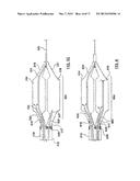 | 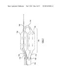 |
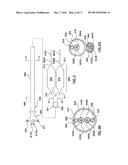 | 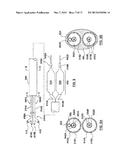 |
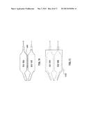 | 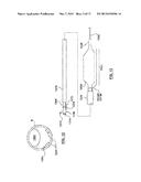 |
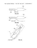 | 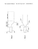 |
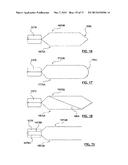 |
| Similar patent applications: | |
| Date | Title |
|---|---|
| 2015-05-14 | Surgical fastener deployment system |
| 2015-05-21 | Adjustable loop constructs and techniques |
| 2015-05-21 | Transoral repair of choanal atresia |
| 2015-04-16 | Laparoscopic forceps assembly |
| 2015-04-23 | Hybrid phacoemulsification needle |
| New patent applications in this class: | |
| Date | Title |
|---|---|
| 2016-09-01 | Catheter for plaque stabilisation |
| 2016-06-30 | Cryogenic needle with freeze zone regulation |
| 2015-10-15 | Apparatus and methods for regulating cryogenic treatment |
| 2014-12-18 | All-liquid cryoablation catheter |
| 2014-11-20 | Methods and systems for treatment of occipital neuralgia |
| New patent applications from these inventors: | |
| Date | Title |
|---|---|
| 2020-03-19 | Monitoring and controlling internally administered cryotherapy |
| 2016-02-11 | Cryoablation apparatuses, systems, and methods for renal neuromodulation |
| 2015-09-10 | Monitoring and controlling internally administered cryotherapy |
| 2015-05-28 | Systems, devices and methods for cryogenic renal neuromodulation |
| 2015-03-26 | Cryotherapeutic devices for renal neuromodulation and associated systems and methods |
| Top Inventors for class "Surgery" | |
| Rank | Inventor's name |
|---|---|
| 1 | Lutz Biedermann |
| 2 | Roger P. Jackson |
| 3 | Wilfried Matthis |
| 4 | Frederick E. Shelton, Iv |
| 5 | Joseph D. Brannan |