Patent application title: FAN AND IMPELLER THEREOF
Inventors:
Shiman Xu (Chaozhou City, CN)
Jiasheng Lai (Boluo County, CN)
Wen-Chun Hsu (New Taipei City, TW)
IPC8 Class: AF04D1702FI
USPC Class:
416189
Class name: Fluid reaction surfaces (i.e., impellers) rotor having flow confining or deflecting web, shroud or continuous passage axially extending shroud ring or casing
Publication date: 2015-03-05
Patent application number: 20150064011
Abstract:
An impeller includes a fan frame, a hub, a plurality of axial blades and
a plurality of wind guiding blades. The fan frame has a wind inlet, a
wind outlet and an inner ring-shaped oblique surface, wherein the wind
inlet is opposite to the wind outlet, and the inner ring-shaped oblique
surface is formed at an inner side wall of the fan frame and adjacent to
the wind inlet. The hub is disposed in the fan frame. The axial blades
are connected to the inner side wall of the fan frame and the hub. The
wind guiding blades protrude from the inner ring-shaped oblique surface.Claims:
1. An impeller comprising: a fan frame having a wind inlet, a wind outlet
and an inner ring-shaped oblique surface, the wind inlet being opposite
to the wind outlet, the inner ring-shaped oblique surface being formed at
an inner side wall of the fan frame and adjacent to the wind inlet; a hub
disposed in the fan frame; a plurality of axial blades connected to the
inner side wall of the fan frame and the hub; and a plurality of wind
guiding blades protruding from the inner ring-shaped oblique surface.
2. The impeller of claim 1, wherein an internal diameter of the fan frame along the inner ring-shaped oblique surface decreases gradually from the wind inlet to the wind outlet, such that the wind outlet is smaller than the wind inlet.
3. The impeller of claim 1, wherein the axial blades and the wind guiding blades are arranged interlacedly.
4. The impeller of claim 1, further comprising a plurality of centrifugal blades connected to an outer side wall of the fan frame.
5. The impeller of claim 1, wherein each of the axial blades has a recess portion and the recess portion faces the wind outlet.
6. A fan comprising: a stator; and an impeller rotatably disposed on the stator, the impeller comprising: a fan frame having a wind inlet, a wind outlet and an inner ring-shaped oblique surface, the wind inlet being opposite to the wind outlet, the inner ring-shaped oblique surface being formed at an inner side wall of the fan frame and adjacent to the wind inlet; a hub disposed in the fan frame; a plurality of axial blades connected to the inner side wall of the fan frame and the hub; and a plurality of wind guiding blades protruding from the inner ring-shaped oblique surface.
7. The fan of claim 6, wherein an internal diameter of the fan frame along the inner ring-shaped oblique surface decreases gradually from the wind inlet to the wind outlet, such that the wind outlet is smaller than the wind inlet.
8. The fan of claim 6, wherein the axial blades and the wind guiding blades are arranged interlacedly.
9. The fan of claim 6, wherein the impeller further comprises a plurality of centrifugal blades connected to an outer side wall of the fan frame.
10. The fan of claim 6, wherein each of the axial blades has a recess portion and the recess portion faces the wind outlet.
Description:
BACKGROUND OF THE INVENTION
[0001] 1. Field of the Invention
[0002] The invention relates to a fan and an impeller thereof and, more particularly, to an impeller capable of increasing wind flux at the wind inlet and outlet effectively and a fan equipped with the impeller.
[0003] 2. Description of the Prior Art
[0004] Heat dissipating device is a significant component for electronic products. When an electronic product is operating, the current in circuit will generate unnecessary heat due to impedance. If the heat is accumulated in the electronic components of the electronic product without dissipating immediately, the electronic components may get damage due to the accumulated heat. Therefore, the performance of heat dissipating device is a significant issue for the electronic product. So far the heat dissipating device used in the electronic product usually consists of a heat pipe, a heat dissipating fin and a fan, wherein a heat absorbing segment of the heat pipe contacts the electronic component, which generates heat during operation, a heat dissipating segment of the heat pipe is connected to the heat dissipating fin, and the fan blows air to the heat dissipating fin, so as to dissipate heat. However, the axial wind flux at the wind inlet and outlet of a conventional fan is limited, and the size of the wind inlet is the same as the size of the wind outlet, such that the wind flux cannot be directed to the heat source effectively. Accordingly, the heat dissipating effect is limited.
SUMMARY OF THE INVENTION
[0005] The invention provides an impeller capable of increasing wind flux at the wind inlet and outlet effectively and a fan equipped with the impeller, so as to solve the aforesaid problems.
[0006] According to an embodiment of the invention, an impeller comprises a fan frame, a hub, a plurality of axial blades and a plurality of wind guiding blades. The fan frame has a wind inlet, a wind outlet and an inner ring-shaped oblique surface, wherein the wind inlet is opposite to the wind outlet, and the inner ring-shaped oblique surface is formed at an inner side wall of the fan frame and adjacent to the wind inlet. The hub is disposed in the fan frame. The axial blades are connected to the inner side wall of the fan frame and the hub. The wind guiding blades protrude from the inner ring-shaped oblique surface.
[0007] In this embodiment, an internal diameter of the fan frame along the inner ring-shaped oblique surface decreases gradually from the wind inlet to the wind outlet, such that the wind outlet is smaller than the wind inlet.
[0008] According to another embodiment of the invention, a fan comprises a stator and an impeller. The impeller is rotatably disposed on the stator. The impeller comprises a fan frame, a hub, a plurality of axial blades and a plurality of wind guiding blades. The fan frame has a wind inlet, a wind outlet and an inner ring-shaped oblique surface, wherein the wind inlet is opposite to the wind outlet, and the inner ring-shaped oblique surface is formed at an inner side wall of the fan frame and adjacent to the wind inlet. The hub is disposed in the fan frame. The axial blades are connected to the inner side wall of the fan frame and the hub. The wind guiding blades protrude from the inner ring-shaped oblique surface.
[0009] In this embodiment, an internal diameter of the fan frame along the inner ring-shaped oblique surface decreases gradually from the wind inlet to the wind outlet, such that the wind outlet is smaller than the wind inlet.
[0010] As mentioned in the above, the invention adds the wind guiding blades onto the inner ring-shaped oblique surface adjacent to the wind inlet, so as to increasing the axial wind flux at the wind inlet and outlet effectively. Furthermore, since the internal diameter of the fan frame along the inner ring-shaped oblique surface decreases gradually from the wind inlet to the wind outlet, the wind flux blown from the wind inlet will be pressurized according to Venturi tube principle, so as to enhance the heat dissipating effect at the hub. Moreover, since the wind outlet is smaller than the wind inlet of the fan frame, the wind flux blown from the wind inlet can be directed to the heat source effectively due to the smaller wind outlet, so as to enhance the heat dissipating effect.
[0011] These and other objectives of the present invention will no doubt become obvious to those of ordinary skill in the art after reading the following detailed description of the preferred embodiment that is illustrated in the various figures and drawings.
BRIEF DESCRIPTION OF THE DRAWINGS
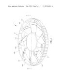
[0012] FIG. 1 is an assembly view illustrating a fan according to an embodiment of the invention.
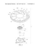
[0013] FIG. 2 is an exploded view illustrating the fan shown in FIG. 1.
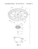
[0014] FIG. 3 is an exploded view illustrating the fan shown in FIG. 1 from another viewing angle.
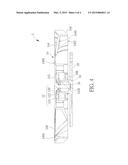
[0015] FIG. 4 is a cross-sectional view illustrating the fan along line A-A shown in FIG. 1.
DETAILED DESCRIPTION
[0016] Referring to FIGS. 1 to 4, FIG. 1 is an assembly view illustrating a fan 1 according to an embodiment of the invention, FIG. 2 is an exploded view illustrating the fan 1 shown in FIG. 1, FIG. 3 is an exploded view illustrating the fan 1 shown in FIG. 1 from another viewing angle, and FIG. 4 is a cross-sectional view illustrating the fan 1 along line A-A shown in FIG. 1. As shown in FIGS. 1 to 4, the fan 1 comprises a base 10, a stator 12, an impeller 14, a bearing 16 and a wearproof member 18. The base 10 has an axial tube 100. The bearing 16 and the wearproof member 18 are disposed in the axial tube 100. The stator 12 is sleeved on the axial tube 100. The stator 12 comprises an upper insulated frame 120, a silicon steel sheet assembly 122 and a lower insulated frame 124. The silicon steel sheet assembly 122 is sandwiched in between the upper insulated frame 120 and the lower insulated frame 124, wherein the silicon steel sheet assembly 122 essentially consists of a plurality of silicon steel sheets stacked with each other. In practical applications, a metal coil (not shown) is wound around the teeth of the upper insulated frame 120, the silicon steel sheet assembly 122 and the lower insulated frame 124.
[0017] The impeller 14 comprises a fan frame 140, a hub 142, a plurality of axial blades 144, a plurality of wind guiding blades 146 and a plurality of centrifugal blades 148. The fan frame 140 has a wind inlet 1400, a wind outlet 1402 and an inner ring-shaped oblique surface 1404, the wind inlet 1400 is opposite to the wind outlet 1402, the inner ring-shaped oblique surface 1404 is formed at an inner side wall of the fan frame 140 and adjacent to the wind inlet 1400. The hub 142 is disposed in the fan frame 140. The hub 142 has a pivot 1420. The pivot 1420 is inserted into the bearing 16 and abuts against the wearproof member 18, such that the impeller 14 is rotatably disposed on the stator 12. The axial blades 144 are connected to the inner side wall of the fan frame 140 and the hub 142. The wind guiding blades 146 protrude from the inner ring-shaped oblique surface 1404. In other words, the wind guiding blades 146 are adjacent to the wind inlet 1400 of the fan frame 140. As shown in FIG. 4, an internal diameter of the fan frame 140 at the wind inlet 1400 along the inner ring-shaped oblique surface 1404 decreases gradually from the wind inlet 1400 to the wind outlet 1402, such that the wind outlet 1402 is smaller than the wind inlet 1400. In this embodiment, the axial blades 144 and the wind guiding blades 146 are arranged, but not limited to, interlacedly. In another embodiment, more than one wind guiding blade 146 may be disposed between two axial blades 144 according to practical applications. The centrifugal blades 148 are connected to an outer side wall of the fan frame 140.
[0018] When the hub 142 rotates with respect to the stator 12, the hub 142 will drive the axial blades 144, the fan frame 140, the wind guiding blades 146 and the centrifugal blades 148 to rotate simultaneously. At this time, the rotating axial blades 144 will blow air into the fan frame 140 from the wind inlet 1400. At the same time, the wind guiding blades 146 adjacent to the wind inlet 1400 can increase the axial wind flux at the wind inlet effectively. Since the wind flux at the wind inlet increases, the wind flux blown out of the wind outlet 1402 of the fan frame 140 will increase accordingly, so as to enhance the heat dissipating effect effectively. Furthermore, since the internal diameter of the fan frame 140 at the wind inlet 1400 along the inner ring-shaped oblique surface 1404 decreases gradually from the wind inlet 1400 to the wind outlet 1402, the wind flux blown from the wind inlet 1400 will be pressurized according to Venturi tube principle, so as to enhance the heat dissipating effect at the hub 142. Moreover, since the wind outlet 1402 is smaller than the wind inlet 1400, the wind flux blown from the wind inlet 1400 can be directed to the heat source (not shown) effectively due to the smaller wind outlet 1402, so as to enhance the heat dissipating effect. Still further, the rotating centrifugal blades 148 will blow the air to the surroundings, so as to enhance the heat dissipating effect around the fan 1. In other words, the fan 1 of the invention has the functions of centrifugal fan and axial fan.
[0019] In this embodiment, each of the axial blades 144 has a recess portion 1440 and the recess portion 1440 faces the wind outlet 1402. Accordingly, when the impeller 14 is rotating, the recess portion 1440 of the axial blade 144 can reduce noise effectively.
[0020] As mentioned in the above, the invention adds the wind guiding blades onto the inner ring-shaped oblique surface adjacent to the wind inlet, so as to increasing the axial wind flux at the wind inlet and outlet effectively. Furthermore, since the internal diameter of the fan frame along the inner ring-shaped oblique surface decreases gradually from the wind inlet to the wind outlet, the wind flux blown from the wind inlet will be pressurized according to Venturi tube principle, so as to enhance the heat dissipating effect at the hub. Moreover, since the wind outlet is smaller than the wind inlet of the fan frame, the wind flux blown from the wind inlet can be directed to the heat source effectively due to the smaller wind outlet, so as to enhance the heat dissipating effect. Still further, the invention may form the recess portion on one side of the axial blade facing the wind outlet, so as to reduce noise while the impeller is rotating.
[0021] Those skilled in the art will readily observe that numerous modifications and alterations of the device and method may be made while retaining the teachings of the invention. Accordingly, the above disclosure should be construed as limited only by the metes and bounds of the appended claims.
User Contributions:
Comment about this patent or add new information about this topic:
Images included with this patent application:
 |  |
 |  |
 |
| Similar patent applications: | |
| Date | Title |
|---|---|
| 2009-07-09 | Fan and impeller |
| 2015-03-19 | Repaired turbine rotor wheel dovetail and related method |
| 2015-02-05 | Fan assembly and method |
| 2015-03-19 | Vertical-axis wind power generator having adjustable-angle rotating blades |
| 2015-03-19 | Tightening and oil discharging nut, and a turbine engine |
| New patent applications in this class: | |
| Date | Title |
|---|---|
| 2016-06-30 | Method of manufacturing centrifugal fan |
| 2016-06-23 | Turbine shroud |
| 2016-04-28 | Centrifugal fan, air-conditioning apparatus, and method of manufacturing centrifugal fan |
| 2016-04-28 | Gas turbine engine with seal inspection features |
| 2016-03-31 | Turbine wheel for a turbine engine |
| New patent applications from these inventors: | |
| Date | Title |
|---|---|
| 2015-03-12 | Heat-dissipating device for interface card |
| Top Inventors for class "Fluid reaction surfaces (i.e., impellers)" | |
| Rank | Inventor's name |
|---|---|
| 1 | Frank B. Stamps |
| 2 | Ching-Pang Lee |
| 3 | Gabriel L. Suciu |
| 4 | Stefan Herr |
| 5 | Tracy A. Propheter-Hinckley |