Patent application title: SPICE GRINDER
Inventors:
Josef Burger (Ravelsbach, AU)
IPC8 Class: AA47J4238FI
USPC Class:
241168
Class name: Solid material comminution or disintegration apparatus hand support comminutor
Publication date: 2015-02-26
Patent application number: 20150053802
Abstract:
A grinder has a jar having a surface provided with a screwthread. A
grinding cap has a lower part engageable over the surface of the jar and
provided with a screwthread such that the lower part can be screwed onto
the jar and an upper part rotatable on the lower part. Grinding
formations on the parts are effective on relative rotation of the parts.
A ramp projects radially from the jar surface toward the cap surface, and
a generally angularly extending and radially elastically deflectable arm
has an inner end fixed on the cap surface and an outer end spaced in a
relaxed condition of the arm radially outward from the cap surface toward
the jar surface. The arm is oriented to engage and have its outer end
deflected radially toward the cap surface by the ramp on screwing of the
lower part onto the jar.Claims:
1. In a grinder comprising: a vessel adapted to hold a material to be
ground and having a surface centered on an axis and provided with a
screwthread formation; and a grinding cap having a lower part engageable
into or over the surface of the vessel and provided with a screwthread
formation complementary to that of the vessel such that the lower part
can be screwed to the vessel, an upper part rotatable on the lower part,
and grinding formations on the parts effective on relative rotation of
the parts to grind the material in the vessel, the improvement
comprising: a blocking formation projecting radially from one of the
surfaces toward the other surface; and a generally angularly extending
and radially elastically deflectable arm having an inner end fixed on the
other surface and an outer end spaced in a relaxed condition of the arm
radially outward from the other surface toward the one surface, the arm
being oriented to engage and have its outer end deflected radially toward
the other surface by the blocking formation on screwing of the lower part
onto the vessel.
2. The grinder defined in claim 1, wherein the blocking formation has, relative to a rotation direction of the cap relative to the vessel on screwing the cap onto the vessel, a downstream shallow flank and an upstream steep flank, the outer end of the arm being directly angularly juxtaposed with the steep flank after passing over the blocking formation on screwing of the cap onto or into the vessel.
3. The grinder defined in claim 2, wherein the outer end is flat and extends generally radially of the axis and parallel to the steep flank in the relaxed condition of the arm but extends at a small acute angle to a radius from the axis on deflection by the blocking formation.
4. The grinder defined in claim 2, wherein the arm is on the surface of the cap and the blocking formation on the surface of the vessel.
5. The grinder defined in claim 4, wherein the arm is unitarily formed with the lower part.
Description:
FIELD OF THE INVENTION
[0001] The present invention relates to a grinder. More particularly this invention concerns a spice grinder for culinary purposes.
BACKGROUND OF THE INVENTION
[0002] The invention relates to a spice grinder that can be screwed onto a jar containing a spice, where the jar has at least one outward projection that interacts in such a way with an inward projection or a part of the spice grinder that is to be screwed onto the jar so as to block any reverse rotation after the two projections have moved past each other as the spice grinder is screwed onto the jar.
[0003] It is frequently desirable or even necessary to close a container provided with a screw-type closure in such a way that the container can no longer be opened be turning the screw-type closure in the reverse direction. In this manner inadvertent removal of the cap and spilling the contents is avoided. This is also true of glass spice containers onto which a spice grinder, typically of plastic, can be installed. These units involving a jar with a spice grinder built into the cap are disposable items, not intended for refilling.
[0004] Approaches have already been proposed for preventing the spice grinder from being unscrewed from the jar. These spice grinders have the features described above. For instance, US 2012/0286081 proposes providing complementary ramp or sawtooth shaped structures on the cap and on the jar, with their shallow and steep flanks oriented oppositely. The cap can be screwed on with the shallow flanks of the formations meeting and sliding over one another with elastic deformation of the cap and/or jar when the cap is first screwed onto the jar. Once screwed on, revers rotation of the cap on the jar will cause the two steep flanks to angularly flatly abut each other, thereby blocking removal of the cap.
[0005] Instead of two ramp formation, U.S. Pat. No. 4,669,614 proposes one ramp formation coacting with another radially projecting ridge of uniform radial height. Similarly EP 0,571,780 proposes ramp-shaped formations on one of the screwthreads that cuts into the material of the other part and inhibits reverse rotation. The functioning is similar.
[0006] The problem with these systems is that substantial deformation of the jar neck and/or cap is necessary to screw the cap onto the jar. The deformation can damage the parts and also makes assembly of the product difficult.
[0007] What more is that with this system the locking is not very strong. The ramps are designed for easy assembly, so that a hard reverse turn can overcome them and unscrew the cap. Since the spice grinder is meant to be used by all types of people, a particularly strong person who reverse-turns the cap can damage the latch and free the cap. What is more on small bottles, it is impossible to provide big enough formations to adequately resist revers rotation. On the other hand large-mouth jars cannot be made flexible enough for the system to work effectively and typically require considerable torque to get the cap properly screwed onto the jar. The problem with large jars is that they must be gripped with considerable radially inwardly effective force, directly counter to the outward radial deflection needed to let the ramps pass each other, especially when the jar is of glass with no meaningful elasticity.
OBJECTS OF THE INVENTION
[0008] It is therefore an object of the present invention to provide an improved spice grinder.
[0009] Another object is the provision of such an improved spice grinder that overcomes the above-given disadvantages, in particular that is easy to assembly, even for a large jar, yet that very strongly resists unscrewing of the cap.
SUMMARY OF THE INVENTION
[0010] A grinder according to the invention has a vessel adapted to hold a material to be ground and having a surface centered on an axis and provided with a screwthread formation. A grinding cap therefore has a lower part engageable into or over the surface of the vessel and provided with a screwthread formation complementary to that of the vessel such that the lower part can be screwed to the vessel and an upper part rotatable about the axis on the lower part. Grinding formations on the parts are effective on relative rotation of the parts to grind the material in the vessel. In accordance with the invention a blocking formation projects radially from one of the surfaces toward the other surface, and a generally angularly extending and radially elastically deflectable arm has an inner end fixed on the other surface and an outer end spaced in a relaxed condition of the arm radially outward from the other surface toward the one surface. The arm is oriented to engage and have its outer end deflected radially toward the other surface by the blocking formation on screwing of the lower part onto the vessel.
[0011] Thus according to the invention when the spice-grinder cap is screwed on, the flexible arm easily slides over the projecting blocking formation on the jar, then snaps back and reliably blocks the grinder from turning in reverse.
[0012] The blocking formation according to the invention has, relative to a rotation direction of the cap relative to the vessel on screwing the cap onto the vessel, a downstream shallow flank and an upstream steep flank. The outer end of the arm is directly angularly juxtaposed with the steep flank after passing over the blocking formation on screwing of the cap onto or into the vessel.
[0013] In addition the outer end of the arm is flat and extends generally radially of the axis and parallel to the steep flank in the relaxed condition of the arm but extends at a small is acute angle to a radius from the axis on deflection by the blocking formation.
[0014] The arm is normally on the surface of the cap, which is typically made of plastic, and the blocking formation on the surface of the vessel, which is typically a glass jar. The arm is unitarily formed with the lower part.
BRIEF DESCRIPTION OF THE DRAWING
[0015] The above and other objects, features, and advantages will become more readily apparent from the following description, reference being made to the accompanying drawing in which:
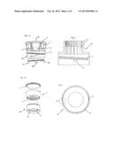
[0016] FIG. 1a is a vertical section through a spice-grinder cap and jar according to the invention;
[0017] FIG. 1b is an exploded view of the grinder cap;
[0018] FIG. 2 is an axial section through the lower part of the cap;
[0019] FIG. 3 is a bottom view of the cap lower part of FIG. 2;
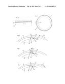
[0020] FIG. 4 is a large-scale side view of the jar neck according to the invention;
[0021] FIG. 5 is a top view of the jar cap; and
[0022] FIGS. 6, 7, and 8 are large-scale schematic bottom views indicating the interaction of the latch formations on the jar and cap as the cap is screwed onto the jar neck.
DETAILED DESCRIPTION OF THE INVENTION
[0023] As seen in FIGS. 1a and 1b a spice-grinder cap has a one-piece upper part 1 and a one-piece lower part 10, both typically injection molded of a hard but elastically deformable plastic and centered on an axis A. A cover 2 is releasably snap-fitted onto the upper part 1. The upper part 1 and lower part 10 are rotatable relative to each other about the axis A, and the lower part 10 can be secured by a radially inwardly open screwthread groove 11 onto a radially outwardly projecting screwthread ridge 14 of a neck of a jar 13. The lower part 10 is provided with teeth 3, while the upper part 1 is provided with teeth 4 that interact therewith to grind spices or similar material as is well known in the art by relative rotation of the two parts 10 and 11 about the axis A. Typically rotation in either direction is used for grinding in an oscillatory motion.
[0024] In use, the cover is removed, the jar 13 is turned upside down, and the two parts 1 and 10 are rotated relative to each other. Inverting the jar 3 dumps unground spices, e.g. peppercorns, from the jar 13 into the part 10, and relative rotation of the parts 1 and 10 causes the built-in grinder formed by the teeth 3 and 4 on the parts 10 and 1 to comminute the unground spices, that then drop out. This is all standard.
[0025] The embodiment according to the invention as described below is provided in order to prevent the spice grinder, in particular, the lower part 10, from being unscrewed from the jar 13 after it has been screwed on. Thus the user will not inadvertently unscrew the entire cap 1, 10 when using the grinder.
[0026] FIGS. 2 and 3 show that at least one, in the example, two inwardly projecting arms 12 are provided diametrally opposite each other on the lower part 10 with the female screwthread formation 11. These arms 12 are elastically radially deflectable and interact with respective ramp-like or sawtooth projections 15 on the jar 13 that is provided with the screwthread formation 14. The outer free end of the arm 12 is radially offset from the inner end fixed to and in fact unitary with the part 10 so the outer arm can be elastically radially deflected relatively easily, yet the arm is very difficult to compress longitudinally.
[0027] It is also within the scope of the invention for the arm 12 to be on the jar 13 and the ramp 15 on the cap part 10, but since the jar 13 is typically made of glass and the part 10 of plastic, the illustrated embodiment with the arm 12 on the part 10 and the ramp 15 on the jar 13 is preferred.
[0028] FIGS. 6 through 8 are schematic views showing the interaction between one of the projections 15 and the respective arm 12 when the lower part 10 is screwed onto the jar 13, or when there is an attempt to unscrew it.
[0029] First, as shown in FIG. 6, when the lower part 10 is screwed in the direction of arrow F1 onto the jar 13, the flexible arm 12 moves past the ramp 15, flexing elastically radially outward about an imaginary pivot point 16 and sliding past the ramp 15. The arm 12 is pushed outward as its outer end slides over the shallow flank 19 of the projection 15.
[0030] Then, as shown in FIG. 7 the flexible arm 12 snaps elastically back inward so that its outer end 17 angularly confronts the steep end face or flank 18 of the projection 15.
[0031] Subsequently, as shown in FIG. 8, an attempt to counterrotate the part 10 in a direction F2 unscrewing it from the jar 13 will only force the end 17 into solid flat contact with the flank 18, thereby solidly opposing unscrewing of the cap. The end 17 is planar and is beveled at an acute angle α relative to the radially extending face 18 to enhance create a wedging effect and force the inner end 17 radially inward.
[0032] Numerous modifications are possible within the scope of the invention. It would thus be possible to dispose a plurality of projections 15 on the jar 13, and a plurality of flexible arms 12 on the lower part 10. The dynamic principle according to the invention could also be applied to other containers that include a screw-type closure.
User Contributions:
Comment about this patent or add new information about this topic:
Images included with this patent application:
 |  |
 |
| Similar patent applications: | |
| Date | Title |
|---|---|
| 2012-11-15 | Spice grinder |
| 2013-10-24 | Spice grinders |
| 2014-10-30 | Spice grinder |
| New patent applications in this class: | |
| Date | Title |
|---|---|
| 2012-10-25 | Grater for single-handed operation |
| 2012-09-27 | Condiment grinder |
| 2012-03-29 | Dough blender |
| 2010-09-02 | single-handed vertical solid material grinder |
| 2010-07-01 | Container with a grinder |
| Top Inventors for class "Solid material comminution or disintegration" | |
| Rank | Inventor's name |
|---|---|
| 1 | Tai Hoon K. Matlin |
| 2 | Charles Sued |
| 3 | Aron Abramson |
| 4 | Knut Kjaerran |
| 5 | Hartmut Pallmann |