Patent application title: Variable rate focus mechanism
Inventors:
David Rogers Campbell (Richland, WA, US)
IPC8 Class: AG02B710FI
USPC Class:
359701
Class name: Adjusting mechanism having cam device cam ring type or zoom ring type
Publication date: 2015-01-29
Patent application number: 20150029598
Abstract:
A focus mechanism has a removable and replaceable cam that allows
selection of different rates of rotation and total axial displacement of
a lens assembly. The rate and displacement are determined by the cam
profile. The rate and displacement of the lens assembly can be selected
by removing a cam with one profile and replacing it with another similar
cam having a different profile. Rotation of an outer ring is coupled to
the cam with drive pins.Claims:
1. An improved focus mechanism with which the axial position of a lens
assembly may be adjusted at a selectable rate, the improvement
comprising: a. a focus ring concentric with said assembly, b. drive pins
to couple the rotation of said ring to said first cam c. a first cam,
concentric with said ring and mechanically coupled to said assembly,
which when rotated, causes axial motion of said assembly according to the
motion of said pins along the profile of said cam.
2. Said first cam being removable and replaceable with a second cam having a different profile.
3. Rotation of said ring causing rotation of said second cam, resulting in a different rate of motion of said assembly with respect to the rate of movement caused by said first cam.
Description:
CROSS-REFERENCE TO RELATED APPLICATIONS
[0001] Not applicable
STATEMENT REGARDING FEDERALLY SPONSORED RESEARCH OR DEVELOPMENT
[0002] Not applicable
THE NAMES OF THE PARTIES TO A JOINT RESEARCH AGREEMENT
[0003] Not applicable
INCORPORATION-BY-REFERENCE OF MATERIAL SUBMITTED ON A COMPACT DISC
[0004] Not applicable
BACKGROUND OF THE INVENTION
[0005] Focus mechanisms are common to photography to adjust the axial position of a lens assembly to cause coincidence of focal planes. In a manual system, rotation of an outer ring causes axial motion of the lens assembly. The rate of motion is determined by the rate of rotation of the ring.
BRIEF SUMMARY OF THE INVENTION
[0006] The present Invention is an improved focus mechanism allowing the rotation of an outer focus ring to cause axial motion of the lens assembly, and allows for variation in the rate of motion of the lens assembly by means of a cam.
BRIEF DESCRIPTION OF THE SEVERAL VIEWS OF THE DRAWINGS
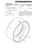
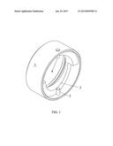
[0007] FIG. 1 is an isometric view of the Invention where (1) is the outer ring, (2) is the cam and (3) and (4) are drive pins.
DETAILED DESCRIPTION OF THE INVENTION
[0008] A lens assembly must be moved along its centerline to achieve focus. Usually a focus mechanism consists of an outer ring that is rotated to cause a corresponding axial motion in the assembly. The rate of axial movement depends on the rate of rotation of the outer ring and that relationship cannot be varied, for example, to select between a coarse movement rate, where one rotation of the ring causes a large axial movement, and a fine rate, where the same rotation results in a small axial movement. Such a selection is useful in achieving first a rough focus, then a very fine movement to set the exact focus. Such would be an advantage, for example, in photography with a high resolution digital sensor where the focus set by eye, at a coarse rate, might not cause the lens assembly to achieve a sufficiently accurate focus, and that resulting in the image, when enlarged, to be out of focus.
[0009] This limitation is solved in the present Invention by means of a cam with a profile that represents a movement rate and maximum movement distance, that can be removed and replaced with another similar cam having a different profile. The first cam could have a profile with a large displacement to allow quick acquisition of a rough focus position, then that cam removed and replaced with a second similar cam with a profile that allows a small displacement, for fine adjustment of the assembly position, thus the focus.
[0010] The mechanism has an outer focus ring which may be adjusted by hand with drive pins secured to the ring. The drive pins bear against the profile of the cam such that rotation of the ring causes rotation of the pins and displacement of the cam and the lens assembly coupled thereto, according to the profile and displacement of the cam profile.
User Contributions:
Comment about this patent or add new information about this topic:
Images included with this patent application:
 |  |
 |
| Similar patent applications: | |
| Date | Title |
|---|---|
| 2015-02-26 | Open architecture structure for trough shaped solar concentrators |
| 2013-04-25 | Focusing mechanism |
| 2015-02-26 | Differential filtering chromatic confocal microscopic system |
| 2015-02-26 | Reworkable filter structure of infrared touch module |
| 2015-02-26 | Variable power optical system |
| New patent applications in this class: | |
| Date | Title |
|---|---|
| 2015-11-19 | Changeable lens barrel |
| 2015-04-02 | Imaging lens barrel |
| 2014-03-20 | Lens advancing device, imaging device equipped with lens advancing device, and portable electronic device |
| 2013-11-21 | Lens barrel and imaging device |
| 2013-05-30 | Zoom lens structure and camera lens |
| New patent applications from these inventors: | |
| Date | Title |
|---|---|
| 2015-01-29 | Control of clamp mechanism by means of a variable thickness disc |
| 2015-01-29 | Tensile loaded leadscrew drive |
| 2009-07-09 | Multi-functional support structure |
| Top Inventors for class "Optical: systems and elements" | |
| Rank | Inventor's name |
|---|---|
| 1 | Tsung Han Tsai |
| 2 | Hsin Hsuan Huang |
| 3 | Michio Cho |
| 4 | Niall R. Lynam |
| 5 | Tsung-Han Tsai |