Patent application title: MEDICAL DEVICE WITH STRETCHABLE ELECTRODE ASSEMBLIES
Inventors:
Derek C. Sutermeister (Ham Lake, MN, US)
IPC8 Class: AA61B1814FI
USPC Class:
606 41
Class name: Instruments electrical application applicators
Publication date: 2015-01-15
Patent application number: 20150018819
Abstract:
Medical devices and methods for making and using medical devices are
disclosed. An example medical device may include a catheter shaft. An
expandable balloon may be coupled to the catheter shaft. The balloon may
be capable of shifting between an unexpanded configuration and an
expanded configuration. Electrode assemblies with electrical pathways may
be coupled to the balloon. The electrical pathways may be capable of
shifting between a serpentine configuration when the balloon is
unexpanded to a straighter configuration when the balloon is expanded.Claims:
1. A medical device for renal nerve ablation, comprising: a catheter
shaft; an expandable member coupled to the catheter shaft, the expandable
member having a proximal region, a distal region, and a body extending
therebetween, the expandable member being capable of moving between an
unexpanded configuration and an expanded configuration; and a plurality
of electrode assemblies fixedly attached to the body of the expandable
member, the plurality of electrode assemblies each including a
stretchable electrical pathway capable of expanding with the expandable
member.
2. The medical device of claim 1, wherein the expandable member is a balloon.
3. The medical device of claim 2, wherein the balloon is a compliant balloon.
4. The medical device of claim 1, wherein each of the electrode assemblies includes at least two electrodes.
5. The medical device of claim 1, wherein when the expandable member is in the unexpanded configuration, the electrical pathways are arranged in a nonlinear configuration.
6. The medical device of any one of claim 5, wherein the nonlinear configuration comprises a serpentine or sinusoidal configuration.
7. The medical device of claim 1, wherein when the expandable member is in the expanded configuration, the electrical pathways expand and move toward a straighter configuration.
8. The medical device of claim 1, wherein the electrode assemblies are printed on the expandable member.
9. The medical device of claim 1, wherein at least some of the electrode assemblies include a pair of adjacent bipolar electrodes.
10. The medical device of claim 1, wherein at least some of the electrode assemblies include a monopolar electrode.
11. The medical device of claim 1, further comprising a temperature sensor disposed on one or more of the plurality of electrode assemblies.
12. The medical device of claim 1, wherein the plurality of electrode assemblies are helically arranged about the body of the expandable member.
13. A medical device for renal nerve ablation, comprising: a catheter shaft; a compliant balloon coupled to the catheter shaft, the compliant balloon capable of shifting between a deflated configuration and an inflated configuration; and a plurality of electrode assemblies fixedly attached to the compliant balloon, the plurality of electrode assemblies including a plurality of stretchable electrical pathways capable of stretching when the compliant balloon shifts to the inflated configuration, wherein the stretchable electrical pathways are capable of shifting between a nonlinear configuration when the balloon is in the deflated configuration toward a straighter configuration when the balloon is in the inflated configuration.
14. The medical device of claim 13, wherein the stretchable electrical pathways have a serpentine or sinusoidal orientation when in the nonlinear configuration.
15. The medical device of claim 13, wherein the electrode assemblies and the stretchable electrical pathways are printed directly on the compliant balloon.
16. The medical device of claim 13, further comprising at least one temperature sensor disposed on the compliant balloon.
17. The medical device of claim 13, wherein at least some of the plurality of electrode assemblies include a pair of adjacent bipolar electrodes.
18. The medical device of claim 13, wherein at least some of the electrode assemblies include a resistive member.
19. The medical device of claim 18, wherein the resistive member forms a microheater.
20. A method for ablating renal nerves, the method comprising: providing a medical device, the medical device comprising: a catheter shaft; a compliant balloon coupled to the catheter shaft, the compliant balloon capable of shifting between a deflated configuration and an inflated configuration, and a plurality of electrode assemblies fixedly attached to the compliant balloon, the plurality of electrode assemblies including a plurality of stretchable electrical pathways capable of stretching when the compliant balloon shifts to the inflated configuration, wherein the stretchable electrical pathways are capable of shifting between a nonlinear configuration when the balloon is in the deflated configuration toward a straighter configuration when the balloon is in the inflated configuration; advancing the medical device through a blood vessel to a position within a renal artery; inflating the compliant balloon; wherein inflating the compliant balloon shifts the stretchable electrical pathways from the nonlinear configuration toward the straighter configuration; activating at least some of the electrode assemblies; and deflating the balloon; wherein deflating the balloon shifts the stretchable electrical pathways to the nonlinear configuration.
Description:
CROSS-REFERENCE TO RELATED APPLICATIONS
[0001] This application claims priority under 35 U.S.C. §119 to U.S. Provisional Application Ser. No. 61/845,291, filed Jul. 11, 2013, the entirety of which is incorporated herein by reference.
TECHNICAL FIELD
[0002] The present disclosure pertains to medical devices, and methods for manufacturing medical devices. More particularly, the present disclosure pertains to medical devices for renal nerve ablation.
BACKGROUND
[0003] A wide variety of intracorporeal medical devices have been developed for medical use, for example, intravascular use. Some of these devices include guidewires, catheters, and the like. These devices are manufactured by any one of a variety of different manufacturing methods and may be used according to any one of a variety of methods. Of the known medical devices and methods, each has certain advantages and disadvantages. There is an ongoing need to provide alternative medical devices as well as alternative methods for manufacturing and using medical devices.
BRIEF SUMMARY
[0004] This disclosure provides design, material, manufacturing method, and use alternatives for medical devices. An example medical device includes a medical device for renal nerve ablation. The medical device may include a catheter shaft, an expandable member coupled to the catheter shaft, the expandable member having a proximal region, a distal region, and a body extending therebetween, the expandable member being capable of moving between an unexpanded configuration and an expanded configuration, and a plurality of electrode assemblies fixedly attached to the body of the expandable member, the plurality of electrode assemblies each including a stretchable electrical pathway capable of expanding with the expandable member.
[0005] In some embodiments, when the expandable member is in the unexpanded configuration, the electrical pathways are arranged in a nonlinear configuration. The nonlinear configuration may be a serpentine or sinusoidal configuration. When the expandable member is in the expanded configuration, the electrical pathways may expand and move toward a straighter configuration.
[0006] In some embodiments a medical device for renal nerve ablation includes a catheter shaft, a compliant balloon coupled to the catheter shaft, the compliant balloon capable of shifting between a deflated configuration and an inflated configuration, and a plurality of electrode assemblies fixedly attached to the compliant balloon, the plurality of electrode assemblies including a plurality of stretchable electrical pathways capable of stretching when the compliant balloon shifts to the inflated configuration, wherein the stretchable electrical pathways are capable of shifting between a nonlinear configuration when the balloon is in the deflated configuration toward a straighter configuration when the balloon is in the inflated configuration.
[0007] In some embodiments, a method for ablating renal nerves includes providing a medical device, the medical device comprising a catheter shaft, a compliant balloon coupled to the catheter shaft, the compliant balloon capable of shifting between a deflated configuration and an inflated configuration, and a plurality of electrode assemblies fixedly attached to the compliant balloon, the plurality of electrode assemblies including a plurality of stretchable electrical pathways capable of stretching when the compliant balloon shifts to the inflated configuration, wherein the stretchable electrical pathways are capable of shifting between a nonlinear configuration when the balloon is in the deflated configuration to a linear configuration when the balloon is in the inflated configuration. The method may further include advancing the medical device through a blood vessel to a position within a renal artery, inflating the compliant balloon, wherein inflating the compliant balloon shifts the stretchable electrode pathways from the nonlinear configuration toward the straighter configuration, activating at least some of the electrode assemblies, and deflating the balloon, wherein deflating the balloon shifts the stretchable electrical pathways to the nonlinear configuration.
[0008] The above summary of some embodiments is not intended to describe each disclosed embodiment or every implementation of the present disclosure. The Figures, and Detailed Description, which follow, more particularly exemplify these embodiments.
BRIEF DESCRIPTION OF THE DRAWINGS
[0009] The disclosure may be more completely understood in consideration of the following detailed description in connection with the accompanying drawings, in which:
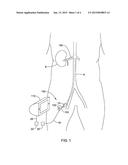
[0010] FIG. 1 is a schematic view of an example renal nerve ablation system;
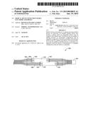
[0011] FIG. 2 is a schematic side view of a portion of an illustrative medical device in an expanded configuration;
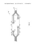
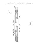
[0012] FIG. 3 is a schematic side view of the medical device of FIG. 2 in an unexpanded configuration; and
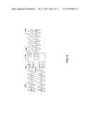
[0013] FIG. 4 is a schematic view of an example electrode assembly.
[0014] While the disclosure is amenable to various modifications and alternative forms, specifics thereof have been shown by way of example in the drawings and will be described in detail. It should be understood, however, that the intention is not to limit the invention to the particular embodiments described. On the contrary, the intention is to cover all modifications, equivalents, and alternatives falling within the spirit and scope of the disclosure.
DETAILED DESCRIPTION
[0015] The following description should be read with reference to the drawings, which are not necessarily to scale, wherein like reference numerals indicate like elements throughout the several views. The detailed description and drawings are intended to illustrate but not limit the claimed invention. Those skilled in the art will recognize that the various elements described and/or shown may be arranged in various combinations and configurations without departing from the scope of the disclosure. The detailed description and drawings illustrate example embodiments of the claimed invention.
[0016] For the following defined terms, these definitions shall be applied, unless a different definition is given in the claims or elsewhere in this specification. All numeric values are herein assumed to be modified by the term "about," whether or not explicitly indicated. The term "about", in the context of numeric values, generally refers to a range of numbers that one of skill in the art would consider equivalent to the recited value (i.e., having the same function or result). In many instances, the term "about" may include numbers that are rounded to the nearest significant figure. Other uses of the term "about" (i.e., in a context other than numeric values) may be assumed to have their ordinary and customary definition(s), as understood from and consistent with the context of the specification, unless otherwise specified.
[0017] The recitation of numerical ranges by endpoints includes all numbers within that range, including the endpoints (e.g. 1 to 5 includes 1, 1.5, 2, 2.75, 3, 3.80, 4, and 5).
[0018] As used in this specification and the appended claims, the singular forms "a", "an", and "the" include plural referents unless the content clearly dictates otherwise. As used in this specification and the appended claims, the term "or" is generally employed in its sense including "and/or" unless the content clearly dictates otherwise.
[0019] It is noted that references in the specification to "an embodiment", "some embodiments", "other embodiments", etc., indicate that the embodiment(s) described may include a particular feature, structure, or characteristic, but every embodiment may not necessarily include the particular feature, structure, or characteristic. Moreover, such phrases are not necessarily referring to the same embodiment. Further, when a particular feature, structure, or characteristic is described in connection with an embodiment, it would be within the knowledge of one skilled in the art to effect such feature, structure, or characteristic in connection with other embodiments, whether or not explicitly described, unless clearly stated to the contrary. That is, the various individual elements described below, even if not explicitly shown in a particular combination, are nevertheless contemplated as being combinable or arrangeable with each other to form other additional embodiments or to complement and/or enrich the described embodiment(s), as would be understood by one of ordinary skill in the art.
[0020] Certain treatments are aimed at the temporary or permanent interruption or modification of select nerve function. One example treatment is renal nerve ablation, which is sometimes used to treat conditions such as or related to hypertension, congestive heart failure, diabetes, or other conditions impacted by high blood pressure or salt retention. The kidneys produce a sympathetic response, which may increase the undesired retention of water and/or sodium. The result of the sympathetic response, for example, may be an increase in blood pressure. Ablating some of the nerves running to the kidneys (e.g., disposed adjacent to or otherwise along the renal arteries) may reduce or eliminate this sympathetic response, which may provide a corresponding reduction in the associated undesired symptoms (e.g., a reduction in blood pressure).
[0021] Some embodiments of the present disclosure relate to a power generating and control apparatus, often for the treatment of targeted tissue in order to achieve a therapeutic effect. In some embodiments, the target tissue is tissue containing or proximate to nerves, including renal arteries and associated renal nerves. In other embodiments the target tissue is luminal tissue, which may further comprise diseased tissue such as that found in arterial disease.
[0022] In some embodiments of the present disclosure, the ability to deliver energy in a targeted dosage may be used for nerve tissue in order to achieve beneficial biologic responses. For example, chronic pain, urologic dysfunction, hypertension, and a wide variety of other persistent conditions are known to be affected through the operation of nervous tissue. For example, it is known that chronic hypertension that may not be responsive to medication may be improved or eliminated by disabling excessive nerve activity proximate to the renal arteries. It is also known that nervous tissue does not naturally possess regenerative characteristics. Therefore it may be possible to beneficially affect excessive nerve activity by disrupting the conductive pathway of the nervous tissue. When disrupting nerve conductive pathways, it is particularly advantageous to avoid damage to neighboring nerves or organ tissue. The ability to direct and control energy dosage is well-suited to the treatment of nerve tissue. Whether in a heating or ablating energy dosage, the precise control of energy delivery as described and disclosed herein may be directed to the nerve tissue. Moreover, directed application of energy may suffice to target a nerve without the need to be in exact contact, as would be required when using a typical ablation probe. For example, eccentric heating may be applied at a temperature high enough to denature nerve tissue without causing ablation and without requiring the piercing of luminal tissue. However, it may also be desirable to configure the energy delivery surface of the present disclosure to pierce tissue and deliver ablating energy similar to an ablation probe with the exact energy dosage being controlled by a power control and generation apparatus.
[0023] Electrical energy dissipation may rely on electrode impedance or on the impedance of the electrode-tissue interface rather than dissipation from the impedance of tissue between active and ground electrodes. Illustratively, whereas typical RF ablation therapies may use medical devices with conductive electrodes, the disclosed concept may include resistive flexible electrode assemblies including one or more of resistive electrodes, a resistive material coated on conductive electrodes, microheaters, and/or other resistors. The use of resistive flexible electrode assemblies, may allow for low voltage ablation devices, where the electrical energy may be provided via direct current or alternating current (e.g., low voltage direct current, low frequency (less than 200 KHz) alternating current, or other energy).
[0024] In some embodiments, efficacy of the denervation treatment can be assessed by measurement before, during, and/or after the treatment to tailor one or more parameters of the treatment to the particular patient or to identify the need for additional treatments. For instance, a denervation system may include functionality for assessing whether a treatment has caused or is causing a reduction in neural activity in a target or proximate tissue, which may provide feedback for adjusting parameters of the treatment or indicate the necessity for additional treatments.
[0025] While the devices and methods described herein are discussed relative to renal nerve ablation and/or modulation, it is contemplated that the devices and methods may be used in other treatment locations and/or applications where nerve modulation and/or other tissue modulation including heating, activation, blocking, disrupting, or ablation are desired, such as, but not limited to: blood vessels, urinary vessels, or in other tissues via trocar and cannula access. For example, the devices and methods described herein can be applied to hyperplastic tissue ablation, cardiac ablation, pulmonary vein isolation, pulmonary vein ablation, tumor ablation, benign prostatic hyperplasia therapy, nerve excitation or blocking or ablation, modulation of muscle activity, hyperthermia or other warming of tissues, ablation within lymphatic vessels or nodes, etc.
[0026] FIG. 1 is a schematic view of an example renal nerve ablation system 100. System 100 may include a renal nerve ablation device 120. Renal nerve ablation device 120 may be used to ablate nerves (e.g., renal nerves) disposed adjacent to the kidney K (e.g., renal nerves disposed about a renal artery RA). In use, renal nerve ablation device 120 may be advanced through a blood vessel such as the aorta A to a position within the renal artery RA. This may include advancing renal nerve ablation device 120 through a guide sheath or catheter 14. When positioned as desired, renal nerve ablation device 120 may be activated to activate one or more electrodes (not shown). This may include operatively coupling renal nerve ablation device 120 to a control unit 110, which may include an RF generator, so as to supply the desired activation energy to the electrodes. For example, renal nerve ablation device 120 may include a wire or conductive member 18 with a connector 20 that can be connected to a connector 22 on the control unit 110 and/or a wire 24 coupled to the control unit 110. In at least some embodiments, the control unit 110 may also be utilized to supply/receive the appropriate electrical energy and/or signal to activate one or more sensors disposed at or near a distal end of renal nerve ablation device 120. When suitably activated, the electrodes may be capable of ablating tissue (e.g., renal nerves) as described below and the sensors may be used to detect desired physical and/or biological parameters.
[0027] In some embodiments, the renal nerve ablation device 120 may include an elongate tubular member or catheter shaft 122. In some embodiments, the elongate tubular member or catheter shaft 122 may be configured to be slidingly advanced over a guidewire or other elongate medical device to a target site. In some embodiments, the elongate tubular member or catheter shaft 122 may be configured to be slidingly advanced within a guide sheath or catheter 14 to a target site. In some embodiments, the elongate tubular member or catheter shaft 122 may be configured to be advanced to a target site over a guidewire, within a guide sheath or catheter 14, or a combination thereof. An expandable member 130 may be disposed at, on, about, or near a distal region of the elongate tubular member or catheter shaft 122, as shown in FIG. 2.
[0028] In some embodiments, as shown in FIG. 2, one or more electrode assemblies 140 may be arranged on the expandable member 130, shown here in an expanded state. The electrode assemblies 140 may be constructed as a flexible substrate attached to the expandable member 130 with one or more electrodes 145 disposed on the substrate. In at least some embodiments, the electrode assemblies 140 are configured to or otherwise capable of expanding with the expandable member 130. For example, in some embodiments, the electrode assemblies 140 may be electrodes and/or conductive pathways that are printed directly on the expandable member 130. In other embodiments, the electrode assemblies 140 may include a substrate that is attached to the expandable member 130. When a substrate is employed, the substrate may be constructed from a polymer such as polyimide, although other materials are contemplated including those disclosed herein.
[0029] Each of the electrode assemblies 140 may include one or more discrete electrical pathways 150, each leading from an electrical contact 155 on an electrode 145 across the expandable member 130. These electrical pathways 150 may include a ground pathway and an active pathway. In some embodiments, a plurality of active pathways may be utilized to power a given electrode 145. Each of the active pathways may supply a portion of the energy used to power the electrode 145. For example, if a given electrode 145 is designed to deliver 1 W of power, two electrical pathways 150 that each supply 0.5 W of power may be coupled to the electrode 145. Analogously, if 1.5 W of power is desired, three electrical pathways 150 may be used (each delivering 0.5 W of power). It can be appreciated that the distribution of power may be altered so that the desired treatment energy can be achieved at the electrodes 145. Furthermore, more or fewer electrical pathways may also be utilized to distribute the desired power.
[0030] In at least some embodiments, the total power that can be delivered by each electrode 145 is substantially equal to the sum of the powers provided by each electrical pathway 150. Because of this, the power delivered by each electrical pathway 150 may be reduced. If further reductions in power are desired, additional electrical pathways 150 may be used. Such arrangements would allow the total power at the electrode 145 to be increased while still being able to utilize low power electrical pathways 150. Because of this, control unit 112 may only need to supply a relatively low amount of power. This may also allow the power source to utilize current as a power source (although alternating current is also contemplated).
[0031] The electrode assemblies 140 may be arranged on the expandable member 130 in a variety of configurations. In some embodiments, the electrode assemblies 140 are offset, as illustrated in FIGS. 2-3. In other embodiments, the electrode assemblies 140 may be linearly arranged along the longitudinal axis of the expandable member 130, aligned along diagonal lines, or they may have a helical orientation along the length of the expandable member 130. In some embodiments, the helical orientation of electrode assemblies 140 forms at least one complete (360 degree) circumferential loop within the lumen or vessel that the expandable member 130 is positioned. The electrode assemblies 140 may provide heating at a location within the tissue surrounding the body passageway without damaging the wall of the body passageway in order to disrupt the nerves located in the tissue surrounding the body passageway wall. A helical orientation may be desirable to help avoid an increased risk of stenosis that may be present when electrodes are disposed within a single plane normal to a longitudinal axis of the body passageway (i.e., a circular electrode or group of electrodes).
[0032] In some embodiments, at least one temperature sensor 160 may be disposed on one or more electrode assemblies 140. The temperature sensor 160 may have an electrical pathway 150 extending from the sensor 160 and across the expandable member 130. In some embodiments, the temperature sensor 160 may be a thermocouple or a thermistor. To help reduce overall thickness, the temperature sensor 160 may be positioned within an opening within the substrate. The temperature sensor 160 may be on a non-tissue contacting side of the electrode assembly 140. Accordingly, the temperature sensor 160 may be captured between the electrode assembly 140 and the expandable member 130 when incorporated into a final device, such as ablation device 120. This may be advantageous since surface-mounted electrical components, like thermistors, typically have sharp edges and corners, which may get caught on tissue and possibly cause problems in balloon deployment and/or retraction.
[0033] In some embodiments, the expandable member 130 is a balloon. In some embodiments, the balloon is a compliant balloon. When a compliant balloon is utilized, tensile and/or other forces may act upon the electrode assemblies 140 (e.g., the electrical pathways 150) when the balloon 130 is expandable. Such forces could undesirably impact the electrical pathways 150. Accordingly, the electrode assemblies 140 and electrical pathways 150 are designed so that they are capable of stretching or otherwise expanding as the compliant balloon is inflated. In some embodiments, the electrical pathways 150 may be disposed directly on or formed within the wall of the compliant balloon 130. In some embodiments the electrical pathways 150 may be printed on the compliant balloon 130. The electrical pathways 150 may be disposed on the balloon 130 in a serpentine or sinusoidal configuration, as illustrated in FIG. 4. As the compliant balloon 130 expands, the serpentine pathways 150 are able to straighten. The serpentine configuration of the pathways 150 on the unexpanded balloon 130 provides excess length or slack in the length of the pathway, allowing for the balloon to expand without breaking or overly distorting the pathways 150. The height and/or spacing of the serpentine waves may be adjusted based on the degree of expansion in the balloon. As illustrated in FIG. 2, when the compliant balloon 130 is in an expanded configuration, the pathways 150 may move towards a straighter configuration, reducing the height of the serpentine waves such that the pathways 150 become more linear. In some embodiments, the electrical pathways 150 may be incorporated into the wall of the compliant balloon 130 during manufacture. In some embodiments, the electrical pathways 150 may be printed directly on the surface of the balloon 130. In some embodiments, the electrical pathways 150 and electrode assemblies 140 may be attached to the surface of the compliant balloon 130 such as by using adhesive.
[0034] As shown in FIG. 4, the electrode assembly 140 may include a plurality of electrodes. In some embodiments, the electrode assemblies include at least two electrodes 145. Each electrode 145 may include at least two electrical contacts 155. Each electrical contact 155 may be connected to a serpentine electrical pathway 150. The electrical contacts 155 may be arranged in groups to form a circuit across which electrical energy is delivered. In some embodiments, six electrical contacts 155 are arranged in groups of three to form a circuit. In some embodiments, each electrode assembly 140 may have radiused corners to reduce tendency to snag on other devices and/or tissue. The electrode assemblies 140 and the pathways 150 associated with them may function in a bi-polar or monopolar mode. In some embodiments, the electrode assembly 140 may deliver at least one watt when apposed against tissue to deliver a denervation therapy. In some embodiments, such as illustrated in FIG. 4, six electrical contacts 155 are arranged in groups of three electrodes 145 with energy delivered across the electrode assembly 140. Each electrical contact 155 may deliver approximately 0.5 watt of energy. The plurality of electrical pathways 150 may allow for a greater total power delivery. A plurality of electrodes may be disposed in close proximity to each other, and may vary in size to achieve a desired power delivery. In some embodiments, a plurality of electrodes 145 may be directly attached to or printed on an expandable member 130, without a substrate. The electrode assemblies 140 or individual electrodes 145 may be arranged on the surface of the expandable member 130 to provide a desired treatment pattern. In some embodiments, the arrangement of electrode assemblies 140 and/or individual electrodes 145 and their associated electrical pathways 150 is selected to achieve a desired configuration when the expandable member 130 is stretched, buckled, twisted, bent, or otherwise manipulated.
[0035] In some embodiments, the renal nerve ablation device 120 may include a bipolar electrode pair. When the renal nerve ablation device 120 is energized, RF energy or other suitable energy may pass from an active electrode, through the vessel wall and the target tissue (e.g., renal nerves), to a ground electrode thereby creating a corresponding lesion or lesions along a body passageway within which the expandable member 130 has been positioned. The temperature sensor 160 may be positioned between the ground electrode and the active electrode. The temperature sensor 160 may be positioned between the ground electrode and the active electrode, and may be configured to monitor the temperature of the target tissue, the active and ground electrodes, or both. In some embodiments, the at least one temperature sensor 160 may include a plurality of temperature sensors configured to monitor the temperature of the target tissue, the active electrodes, the ground electrodes, or any combination thereof, at a plurality of locations along the length of the expandable member 130.
[0036] The system 100 may be used to perform a method of treatment in accordance with one non-limiting embodiment of the disclosure. For example, the control unit 110 may be operationally coupled to the ablation device 120, which may be inserted into a body passageway such that an expandable member 130 (having a plurality of electrode assemblies) may be placed adjacent to a first section of the body passageway where therapy is required. Placement of the ablation device 120 at the first section of the body passageway where therapy is required may be performed according to conventional methods, e.g., over a guidewire under fluoroscopic guidance. Once inserted, the expandable member 130 may be made to expand from a collapsed delivery configuration to an expanded configuration, for example by pressurizing fluid from about 2-10 atm in the case of a balloon. This may cause the electrodes and/or electrode assemblies of the expandable member 130 to come into contact with the first section of the body passageway.
[0037] In some embodiments, the ablation device 120 may be advanced through a blood vessel to a position adjacent to a target tissue (e.g., within a renal artery). In some embodiments, the target tissue may be one or more renal nerves disposed about the renal artery. When suitably positioned, expandable member 130 may be expanded from a collapsed delivery configuration to an expanded configuration. This may place the active electrodes against the wall of the blood vessel. The electrodes 145 may be activated. Ablation energy may be transmitted from the electrodes 145 through the target tissue (where renal nerves may be ablated, modulated, or otherwise impacted).
[0038] The materials that can be used for the various components of the ablation device 120 (and/or other devices disclosed herein) may include those commonly associated with medical devices. For simplicity purposes, the following discussion makes reference to the ablation device 120. However, this is not intended to limit the devices and methods described herein, as the discussion may be applied to other similar tubular members and/or expandable members and/or components of tubular members and/or expandable members disclosed herein.
[0039] The ablation device 120 and the various components thereof may be made from a metal, metal alloy, polymer (some examples of which are disclosed below), a metal-polymer composite, ceramics, combinations thereof, and the like, or other suitable material. Some examples of suitable polymers may include polytetrafluoroethylene (PTFE), ethylene tetrafluoroethylene (ETFE), fluorinated ethylene propylene (FEP), polyoxymethylene (POM, for example, DELRIN® available from DuPont), polyether block ester, polyurethane (for example, Polyurethane 85A), polypropylene (PP), polyvinylchloride (PVC), polyether-ester (for example, ARNITEL® available from DSM Engineering Plastics), ether or ester based copolymers (for example, butylene/poly(alkylene ether) phthalate and/or other polyester elastomers such as HYTREL® available from DuPont), polyamide (for example, DURETHAN® available from Bayer or CRISTAMID® available from Elf Atochem), elastomeric polyamides, block polyamide/ethers, polyether block amide (PEBA, for example available under the trade name PEBAX®), ethylene vinyl acetate copolymers (EVA), silicones, polyethylene (PE), Marlex high-density polyethylene, Marlex low-density polyethylene, linear low density polyethylene (for example REXELL®), polyester, polybutylene terephthalate (PBT), polyethylene terephthalate (PET), polytrimethylene terephthalate, polyethylene naphthalate (PEN), polyetheretherketone (PEEK), polyimide (PI), polyetherimide (PEI), polyphenylene sulfide (PPS), polyphenylene oxide (PPO), poly paraphenylene terephthalamide (for example, KEVLAR®), polysulfone, nylon, nylon-12 (such as GRILAMID® available from EMS American Grilon), perfluoro(propyl vinyl ether) (PFA), ethylene vinyl alcohol, polyolefin, polystyrene, epoxy, polyvinylidene chloride (PVdC), poly(styrene-b-isobutylene-b-styrene) (for example, SIBS and/or SIBS 50A), polycarbonates, ionomers, biocompatible polymers, other suitable materials, or mixtures, combinations, copolymers thereof, polymer/metal composites, and the like. In some embodiments the sheath can be blended with a liquid crystal polymer (LCP). For example, the mixture can contain up to about 6 percent LCP.
[0040] Some examples of suitable metals and metal alloys include stainless steel, such as 304V, 304L, and 316LV stainless steel; mild steel; nickel-titanium alloy such as linear-elastic and/or super-elastic nitinol; other nickel alloys such as nickel-chromium-molybdenum alloys (e.g., UNS: N06625 such as INCONEL® 625, UNS: N06022 such as HASTELLOY® C-22®, UNS: N10276 such as HASTELLOY® C276®, other HASTELLOY® alloys, and the like), nickel-copper alloys (e.g., UNS: N04400 such as MONEL® 400, NICKELVAC® 400, NICORROS® 400, and the like), nickel-cobalt-chromium-molybdenum alloys (e.g., UNS: R30035 such as MP35-N® and the like), nickel-molybdenum alloys (e.g., UNS: N10665 such as HASTELLOY® ALLOY B2®), other nickel-chromium alloys, other nickel-molybdenum alloys, other nickel-cobalt alloys, other nickel-iron alloys, other nickel-copper alloys, other nickel-tungsten or tungsten alloys, and the like; cobalt-chromium alloys; cobalt-chromium-molybdenum alloys (e.g., UNS: R30003 such as ELGILOY®, PHYNOX®, and the like); platinum enriched stainless steel; titanium; combinations thereof; and the like; or any other suitable material.
[0041] As alluded to herein, within the family of commercially available nickel-titanium or nitinol alloys, is a category designated "linear elastic" or "non-super-elastic" which, although may be similar in chemistry to conventional shape memory and super elastic varieties, may exhibit distinct and useful mechanical properties. Linear elastic and/or non-super-elastic nitinol may be distinguished from super elastic nitinol in that the linear elastic and/or non-super-elastic nitinol does not display a substantial "superelastic plateau" or "flag region" in its stress/strain curve like super elastic nitinol does. Instead, in the linear elastic and/or non-super-elastic nitinol, as recoverable strain increases, the stress continues to increase in a substantially linear, or a somewhat, but not necessarily entirely linear relationship until plastic deformation begins or at least in a relationship that is more linear that the super elastic plateau and/or flag region that may be seen with super elastic nitinol. Thus, for the purposes of this disclosure linear elastic and/or non-super-elastic nitinol may also be termed "substantially" linear elastic and/or non-super-elastic nitinol.
[0042] In some cases, linear elastic and/or non-super-elastic nitinol may also be distinguishable from super elastic nitinol in that linear elastic and/or non-super-elastic nitinol may accept up to about 2-5% strain while remaining substantially elastic (e.g., before plastically deforming) whereas super elastic nitinol may accept up to about 8% strain before plastically deforming. Both of these materials can be distinguished from other linear elastic materials such as stainless steel (that can also can be distinguished based on its composition), which may accept only about 0.2 to 0.44 percent strain before plastically deforming.
[0043] In some embodiments, the linear elastic and/or non-super-elastic nickel-titanium alloy is an alloy that does not show any martensite/austenite phase changes that are detectable by differential scanning calorimetry (DSC) and dynamic metal thermal analysis (DMTA) analysis over a large temperature range. For example, in some embodiments, there may be no martensite/austenite phase changes detectable by DSC and DMTA analysis in the range of about -60 degrees Celsius (° C.) to about 120° C. in the linear elastic and/or non-super-elastic nickel-titanium alloy. The mechanical bending properties of such material may therefore be generally inert to the effect of temperature over this very broad range of temperature. In some embodiments, the mechanical bending properties of the linear elastic and/or non-super-elastic nickel-titanium alloy at ambient or room temperature are substantially the same as the mechanical properties at body temperature, for example, in that they do not display a super-elastic plateau and/or flag region. In other words, across a broad temperature range, the linear elastic and/or non-super-elastic nickel-titanium alloy maintains its linear elastic and/or non-super-elastic characteristics and/or properties.
[0044] In some embodiments, the linear elastic and/or non-super-elastic nickel-titanium alloy may be in the range of about 50 to about 60 weight percent nickel, with the remainder being essentially titanium. In some embodiments, the composition is in the range of about 54 to about 57 weight percent nickel. One example of a suitable nickel-titanium alloy is FHP-NT alloy commercially available from Furukawa Techno Material Co. of Kanagawa, Japan. Some examples of nickel titanium alloys are disclosed in U.S. Pat. Nos. 5,238,004 and 6,508,803, which are incorporated herein by reference. Other suitable materials may include ULTANIUM® (available from Neo-Metrics) and GUM METAL® (available from Toyota). In some other embodiments, a superelastic alloy, for example a superelastic nitinol can be used to achieve desired properties.
[0045] In at least some embodiments, portions of the ablation device 120 may also be doped with, made of, or otherwise include a radiopaque material. Radiopaque materials are understood to be materials capable of producing a relatively bright image on a fluoroscopy screen or another imaging technique during a medical procedure. This relatively bright image aids the user of the ablation device 120 in determining its location. Some examples of radiopaque materials can include, but are not limited to, gold, platinum, palladium, tantalum, tungsten alloy, polymer material loaded with a radiopaque filler, and the like. Additionally, other radiopaque marker bands and/or coils may also be incorporated into the design of the ablation device 120 to achieve the same result.
[0046] In some embodiments, a degree of Magnetic Resonance Imaging (MRI) compatibility may be imparted into the ablation device 120. For example, portions of device, may be made of a material that does not substantially distort the image and create substantial artifacts (i.e., gaps in the image). Certain ferromagnetic materials, for example, may not be suitable because they may create artifacts in an MRI image. In some of these and in other embodiments, portions of the ablation device 120 may also be made from a material that the MRI machine can image. Some materials that exhibit these characteristics include, for example, tungsten, cobalt-chromium-molybdenum alloys (e.g., UNS: R30003 such as ELGILOY®, PHYNOX®, and the like), nickel-cobalt-chromium-molybdenum alloys (e.g., UNS: R30035 such as MP35-N® and the like), nitinol, and the like, and others.
[0047] U.S. patent application Ser. No. 13/750,879, published as U.S. Patent Application Pub. No. US 2013/0165926, filed on Jan. 25, 2013, and entitled "METHODS AND APPARATUSES FOR REMODELING TISSUE OF OR ADJACENT TO A BODY PASSAGE" is herein incorporated by reference.
[0048] It should be understood that this disclosure is, in many respects, only illustrative. Changes may be made in details, particularly in matters of shape, size, and arrangement of steps without exceeding the scope of the disclosure. This may include, to the extent that it is appropriate, the use of any of the features of one example embodiment being used in other embodiments. The invention's scope is, of course, defined in the language in which the appended claims are expressed.
User Contributions:
Comment about this patent or add new information about this topic:
| People who visited this patent also read: | |
| Patent application number | Title |
|---|---|
| 20180049749 | Surgery Device for Osteotomy |
| 20180049748 | MULTI-MODE INFLATABLE LIMB OCCLUSION DEVICES AND METHODS |
| 20180049747 | CATHETERS WITH SIDE OPENINGS FOR MODIFYING AND DELIVERING SUSPENSIONS TO A SUBJECT |
| 20180049746 | SYSTEMS AND METHODS FOR DELIVERING AN IMPLANTABLE DEVICE |
| 20180049745 | Hemostasis Reloadable Clipping Device With Sleeve Engagement |
Images included with this patent application:
 |  |
 |  |
 |
| Similar patent applications: | |
| Date | Title |
|---|---|
| 2015-02-12 | Device and method for manipulating intervertebral tissue |
| 2015-02-12 | Device and method for appetite suppression and weight loss management |
| 2014-11-06 | Adjustable rod assembly |
| 2015-02-12 | Bulbous balloon with mechanical pressure regulator |
| 2015-02-12 | Device and method for preparing a recess in a bone |
| New patent applications in this class: | |
| Date | Title |
|---|---|
| 2022-05-05 | Apparatus and method of assessing transvascular denervation |
| 2022-05-05 | Systems and methods for ablation using non-adjacent bipoles |
| 2022-05-05 | Needle tip to apply current, handpiece, and apparatus for treating skin |
| 2022-05-05 | Treatment apparatus and method of controlling same |
| 2022-05-05 | Arthroscopic devices and methods |
| New patent applications from these inventors: | |
| Date | Title |
|---|---|
| 2021-06-17 | Pulmonary vein isolation balloon catheter |
| 2021-06-17 | Cryogenic ablation system |
| 2021-06-17 | Pulmonary vein isolation balloon catheter |
| 2021-06-17 | Apparatus and system for cryo-therapy balloon |
| 2017-01-26 | Actuated extra-venous valve |
| Top Inventors for class "Surgery" | |
| Rank | Inventor's name |
|---|---|
| 1 | Lutz Biedermann |
| 2 | Roger P. Jackson |
| 3 | Wilfried Matthis |
| 4 | Frederick E. Shelton, Iv |
| 5 | Joseph D. Brannan |