Patent application title: WEAR PAD ASSEMBLY
Inventors:
Paul Anthony Sheehan (Leicester Forest East, GB)
Adrian Paul Forrester (Leicester, GB)
Assignees:
Caterpillar Inc.
IPC8 Class: AE02F928FI
USPC Class:
37452
Class name: Excavating digging edge tooth or adaptor
Publication date: 2014-11-27
Patent application number: 20140345172
Abstract:
The present disclosure relates to a wear pad assembly for mounting on a
tool. The problem addressed is the mounting of the wear pad assembly such
that it can be quickly attached to a tool in a non-permanent manner. The
disclosure provides a wear pad assembly for a tool comprising an edge
provided with one or more holes. The wear pad assembly comprises a
wear-resistant pad, a mounting bracket configured for attachment to the
wear-resistant pad, and a quick-release pin for securing the wear pad
assembly to the tool edge.Claims:
1. A wear pad assembly for a tool comprising an edge provided with one or
more holes, the wear pad assembly comprising: a wear-resistant pad; a
mounting bracket configured for attachment to the wear-resistant pad; and
a quick-release pin for securing the wear pad assembly to the tool edge.
2. A wear pad assembly according to claim 1, wherein the mounting bracket is configured for releasable attachment to the wear-resistant pad.
3. A wear pad assembly according to claim 1, wherein the mounting bracket comprises a generally C-shaped element.
4. A wear pad assembly according to claim 1, wherein the mounting bracket comprises one or more pairs of coaxial holes for receiving the pin.
5. A wear pad assembly according to claim 4, further comprising a loose collar for taking up clearance between the one or more pairs of coaxial holes and the pin.
6. A wear pad assembly according to claim 1, wherein the mounting bracket further comprises an attachment surface for attachment to the wear-resistant pad, the attachment surface comprising one or more shear lugs.
7. A wear pad assembly according to claim 6, wherein the wear-resistant pad comprises one or more blind holes for receiving the one or more shear lugs of the mounting bracket.
8. A wear pad assembly according to claim 1, wherein the wear-resistant pad comprises one or more through holes for receiving fasteners for attachment of the wear-resistant pad to the mounting bracket.
9. A wear pad assembly according to claim 8, wherein the one or more through holes are counterbored.
10. A wear pad assembly according to claim 8, wherein one or more blind holes for receiving the fasteners and the one or more through holes are coincident.
11. A wear pad assembly according to claim 1, further comprising a locking mechanism for locking the pin.
12. A wear pad assembly according to claim 11, wherein the locking mechanism is a linchpin.
13. A machine having a tool comprising an edge provided with one or more holes, and further comprising at least one wear pad assembly according to claim 1.
14. A machine according to claim 13, wherein the tool is a bucket.
15. A machine according to claim 14, wherein the bucket is a loader bucket.
16. A machine comprising: a tool comprising an edge provided with one or more holes; and a wear pad assembly, said wear pad assembly comprising: a wear-resistant pad; a mounting bracket configured for attachment to the wear-resistant pad; and a quick-release pin for securing the wear pad assembly to the tool edge, wherein the mounting bracket is configured for releasable attachment to the wear-resistant pad and wherein the mounting bracket comprises one or more pairs of coaxial holes for receiving the pin.
17. The machine of claim 16, further comprising a loose collar for taking up clearance between the one or more pairs of coaxial holes and the pin.
18. The machine of claim 16, wherein the mounting bracket further comprises an attachment surface for attachment to the wear-resistant pad, the attachment surface comprising one or more shear lugs.
19. The machine of claim 18, wherein the wear-resistant pad comprises one or more blind holes for receiving the one or more shear lugs of the mounting bracket.
20. The machine of claim 16, wherein the mounting bracket comprises a generally C-shaped element.
Description:
TECHNICAL FIELD
[0001] This disclosure is directed to a wear pad assembly for a work tool, and in particular to a wear pad assembly for use with work tools having bucket-like elements, such as front end loaders.
BACKGROUND
[0002] Work machines, such as backhoe loaders, are commonly operated on hard finished surfaces such as tarmac work surfaces or roads. In order to stabilise the machine when working, rear stabiliser pads and a front end work tool, such as a loader, are lowered to ground level. However, the forces on the surface resulting from the weight and movement of the machine can result in damage to the surface, which may lead to a penalty or re-work costs for the operator or contractor.
[0003] In order to address this problem, it is known to affix wear pads to the rear stabilisers, as described in U.S. Pat. No. 6,386,586. Such wear pads have a lower hardness than the road surface, and thus erode in preference thereto.
[0004] Similarly, wear pads may also be affixed to the front end work tool. US-A-2006/0145489 discloses an apparatus for protecting a floor or surface and a bucket or scoop from costly wear and/or damage during material handling operations, wherein the wear pad is configured to be bolted to a bucket or scoop.
[0005] However, the front end work tool is typically used for tasks such as lifting, digging, and loading, which tasks may be impeded by the presence of wear pads. Therefore, it would be desirable to have a wear pad which can be quickly attached to a work tool, such as a front end loader, in a non-permanent manner.
SUMMARY
[0006] According to one aspect of the present disclosure there is provided a wear pad assembly for a work tool comprising an edge provided with one or more holes, the wear pad assembly comprising:
[0007] a wear-resistant pad;
[0008] a mounting bracket configured for attachment to the wear-resistant pad; and
[0009] a quick-release pin for securing the wear pad assembly to the work tool edge.
[0010] One exemplary embodiment of a wear pad assembly is as described with reference to, and as shown in the accompanying drawings.
BRIEF DESCRIPTION OF THE DRAWINGS
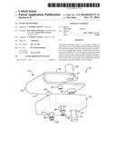
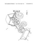
[0011] FIG. 1 is a perspective view of a work machine having a wear pad assembly according to the present disclosure secured thereto;
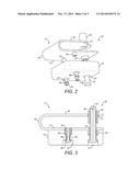
[0012] FIG. 2 is an exploded perspective view of the wear pad assembly of FIG. 1;
[0013] FIG. 3 is a cross-sectional view of the wear pad assembly of FIG. 2;
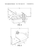
[0014] FIG. 4 is a cross-sectional perspective view of the wear pad of FIGS. 2 and 3 located on a work tool of a work machine; and
[0015] FIG. 5 is a perspective view of the wear pad of FIGS. 2 to 4 located on a work tool of a work machine and secured in place using a linchpin.
DETAILED DESCRIPTION
[0016] FIG. 1 illustrates a work machine 5 having a front end work tool 6, which in the illustrated embodiment is a front end loader. The work tool 6 may be pivotally connected to the work machine 5 via one of more linkage members 7. The work tool 6 may comprise a bucket-like element 8 having an edge 9, commonly known as a cutting edge, which is provided with one or more mounting holes (not shown). The work tool 6 is typically made of steel or a similar material. At least one wear pad assembly 10 is removably attachable to the edge 9 as shown in FIG. 1.
[0017] FIGS. 2 and 3 illustrate the wear pad assembly 10 in greater detail. The wear pad assembly 10 comprises three main components, namely a mounting bracket 11, a wear-resistant pad 12, and a pin 13.
[0018] The mounting bracket 11 may be a generally C-shaped component, having a pair of generally parallel flanges 16,17, comprising an upper flange 16 and a lower flange 17, joined by a curved portion 11. The bracket 11 is thus configured for location on the edge 9 of the work tool 6, as shown in FIG. 4. At least one pair of coaxial holes 31 may be provided in the flanges 16,17, for attachment of the mounting bracket 11 to the edge 9 of the work tool 6.
[0019] The mounting bracket 11 may be provided with shear lugs 23 for assisting in the location of the wear-resistant pad 12 on the mounting bracket 11. The shear lugs 23 also provide stability to the wear-resistant pad 12, as they resist relative transverse movement between the mounting bracket 11 and the wear-resistant pad 12 when the work machine 5 is being operated.
[0020] The mounting bracket 11 may be made from steel or any other suitable material. It may be manufactured by any suitable method, such as fabrication or casting.
[0021] The wear-resistant pad 12 may be provided with blind holes 24 for receiving the shear lugs 23 of the mounting bracket 11. The wear-resistant pad 12 may also comprise through holes 25 for receiving fasteners 26, such as bolts. The through holes 25 may be provided with counterbores 27 such that the heads 30 of the fasteners 26 sit flush with or below the outer surface of the wear-resistant pad 12. The blind holes 24 and the through holes 25 may be coincident.
[0022] This arrangement enables service replacement of the wear-resistant pad 12 as a singular item.
[0023] The wear-resistant pad 12 may be made of a wear-resistant compound, such as polyurethane or neoprene, or any suitable rubber material. The wear-resistant pad 12 may be manufactured from a moulding process. The size of the wear-resistant pad 12, in terms of surface area and thickness, is selected according to front end machine weight distribution and surface pressure of the machine 5 on which the wear-resistant pad 12 is to be used.
[0024] The pin 13 is used to attach the mounting bracket 11 and wear-resistant pad 12 to the work tool 6. The pin 13 may be a quick-release type pin, and passes through coaxial holes 31 in the wear-resistant pad 12 and the flanges 16,17 of the mounting bracket 11. A loose collar 32 may be provided to act as a spacer to take up clearance between the pin 13 and the coaxial hole 31 in the upper flange 16 of the mounting bracket 11, and to ensure a close fit therebetween. The pin 13 may comprise a locking mechanism, such as a hole 33 in its upper end for receiving a split pin or a quick-release linchpin 34 (as shown in FIG. 5).
[0025] The pin 13 may be made of a steel material, which may be plated in order to enhance its corrosion resistance.
[0026] The pin 13 enables the wear pad assembly 10 to be quickly and easily fitted to a variety of work tools 6 having one or more mounting holes. The linchpin 34 or other locking mechanism may be fitted and removed without tools.
INDUSTRIAL APPLICABILITY
[0027] The wear pad assembly 10 has industrial applicability in the field of work machines, and may be used on a variety of different work machines, including backhoe loaders, which have a work tool 6 comprising a bucket-like element 8 such as a loader.
[0028] The wear pad assembly 10 is attached and secured to the work tool 6 when it is required to lower the work tool 6 to the ground to act as a stabilising leg for the work machine 5. With the work tool 6 raised off the ground, the C-shaped mounting bracket 11 is located on the edge 9 of the work tool 6 over a hole provided thereon. The collar 32 may be positioned in the aligned hole 31 of the mounting bracket 11. The pin 13 is then inserted through the aligned holes 31, and is secured in place using a linchpin 34 or any other suitable locking mechanism.
[0029] The wear pad assembly 10 according to the disclosure enables a machine operator to easily and quickly fit a wear pad to a front-end bucket 8.
User Contributions:
Comment about this patent or add new information about this topic:
| People who visited this patent also read: | |
| Patent application number | Title |
|---|---|
| 20160068480 | PROCESS FOR THE PREPARATION OF METHIONINE |
| 20160068479 | CCR9 INHIBITORS AND METHODS OF USE THEREOF |
| 20160068478 | NOVEL STAT3 INHIBITORS |
| 20160068477 | METHOD OF MANUFACTURING SULTONIUM SALT |
| 20160068476 | PROCESS FOR CHOLINE HYDROXIDE |
Images included with this patent application:
 |  |
 |  |
| Similar patent applications: | |
| Date | Title |
|---|---|
| 2014-12-25 | Wear pad assembly |
| 2013-07-11 | Plow blade assembly |
| 2014-07-03 | Multipiece wear assembly |
| 2014-08-07 | Wear assembly |
| 2014-11-06 | Wear assembly |
| New patent applications in this class: | |
| Date | Title |
|---|---|
| 2017-08-17 | Ground engaging component and method for manufacturing the same |
| 2016-06-09 | Male and female parts for a wear assembly of an earth-moving machine's bucket |
| 2016-03-24 | Ground engaging tool assembly |
| 2015-04-16 | Implement tooth assembly with tip and adapter |
| 2014-06-26 | Excavating tooth wear indicator and method |
| Top Inventors for class "Excavating" | |
| Rank | Inventor's name |
|---|---|
| 1 | James Robert Lahood |
| 2 | Phillip J. Kunz |
| 3 | Robert N. Gamble, Ii |
| 4 | Mark D. Buckbee |
| 5 | Kent Winter |