Patent application title: DRIVE TRAIN HAVING A SPUR GEARING AND A CENTRIFUGAL PENDULUM
Inventors:
Alain Rusch (Brumath, FR)
Steffen Lehmann (Ettlingen, DE)
Friedrich Gerhardt (Kehl-Leutesheim, DE)
Assignees:
SCHAEFFLER TECHNOLOGIES GMBH & CO. KG
IPC8 Class: AF16F1514FI
USPC Class:
477 70
Class name: Interrelated power delivery controls, including engine control transmission control with clutch control
Publication date: 2014-11-06
Patent application number: 20140329641
Abstract:
A drive train including an internal combustion engine with a crankshaft,
and having a spur gear arrangement with at least one transmission input
shaft that is coupled to the crankshaft by a friction clutch. A clutch
plate within a housing of the friction clutch is connected in a
rotationally locked manner to the at least one transmission input shaft
and includes a centrifugal force pendulum. To accommodate the centrifugal
force pendulum in the drive train in a space saving manner, the
centrifugal force pendulum is situated on the at least one transmission
input shaft at an axial distance from the clutch plate.Claims:
1. A drive train comprising: an internal combustion engine having a
crankshaft; a transmission including spur gears and at least one
transmission input shaft coupled to the crankshaft by a friction clutch
including a clutch plate received within a clutch housing and connected
in a rotationally locked manner to the at least one transmission input
shaft; and a centrifugal force pendulum carried on the at least one
transmission input shaft at an axial distance from the clutch plate.
2. The drive train according to claim 1, wherein the centrifugal force pendulum is situated outside of the clutch housing.
3. The drive train according to claim 1, wherein the centrifugal force pendulum is situated between the internal combustion engine and the friction clutch.
4. The drive train according to claim 1, wherein the centrifugal force pendulum is situated between the friction clutch and the spur gears of the transmission.
5. The drive train according to claim 4, wherein the centrifugal force pendulum is situated within a housing containing the spur gears.
6. The drive train according to claim 1, wherein the centrifugal force pendulum is situated at an end of the transmission input shaft that extends through the spur gears, and the spur gears are positioned between the friction clutch and the centrifugal force pendulum.
7. The drive train according to claim 1, wherein the transmission is a dual-clutch transmission that includes two sub-transmissions, each sub-transmission having a respective transmission input shaft and one sub-transmission having a hollow transmission input shaft, wherein the centrifugal force pendulum is received directly on the hollow transmission input shaft.
8. The drive train according to claim 7, wherein each sub-transmission includes a respective set of spur gears and the centrifugal force pendulum is situated between the sets of spur gears of the sub-transmissions.
9. The drive train according to claim 7, wherein at least one pendulum mass carried by the centrifugal force pendulum is situated radially outwardly of a radially outermost surface of at least one spur gear received on the transmission input shaft, and at least partially axially overlaps the at least one spur gear.
Description:
CROSS-REFERENCE TO RELATED APPLICATION
[0001] This application is a continuation of International Application Serial No. PCT/DE2012/000791, having an international filing date of 6 Aug. 2012, and designating the United States, the entire contents of which are hereby incorporated by reference to the same extent as if fully rewritten.
BACKGROUND OF THE INVENTION
[0002] 1. Field of the Invention
[0003] The present invention relates to a drive train including an internal combustion engine with a crankshaft, and including a spur gear arrangement with at least one transmission input shaft that can be coupled to the crankshaft by means of a friction clutch. A clutch plate that is integrated in a housing of the friction clutch is connected in a rotationally locked manner to the at least one transmission input shaft, includes a centrifugal force pendulum.
[0004] 2. Description of the Related Art
[0005] To reduce torsional vibrations resulting from non-uniformities of rotational speed, for example of a crankshaft of an internal combustion engine, so-called centrifugal force pendulums are situated on a rotating part of the drive train and are provided with masses that are received in such a way that they can pivot in a circumferential direction relative to an axis of rotation. Those masses carry out vibrations on specified paths in the field of centrifugal acceleration when they are excited by rotational speed non-uniformities. Energy is extracted from the exciter vibration and is re-introduced by those vibrations at appropriate times, so that the exciter vibration is calmed; that is, the centrifugal force pendulum acts as a vibration absorber. Since both the natural frequency of the centrifugal force pendulum vibration and the exciter frequency are proportional to the speed of rotation, the vibration damping effect of a centrifugal force pendulum can be achieved over the entire frequency range.
[0006] A drive train with an internal combustion engine having a crankshaft, a spur gear arrangement provided on a transmission input shaft, and a friction clutch that couples the crankshaft and the transmission input shaft, as well as a centrifugal force pendulum that absorbs torsional vibrations of drive train, is known from DE 10 2009 042 831 A1. In that published application the centrifugal force pendulum is received on the friction clutch. The torque is introduced into a spur gear arrangement through the housing of the friction clutch, from the crankshaft through a clutch plate that is connected to the transmission input shaft. Furthermore, the centrifugal force pendulum can be integrated into a torsional vibration damper, such as a dual-mass flywheel, as is seen from DE 10 2010 018 941 A1. It is also known to integrate centrifugal force pendulums into the clutch plate itself.
[0007] The construction space of the drive train is limited for the most part, in particular in the area of torsional vibration dampers, friction clutches, clutch plates, and the like. The transmission of maximum torque has priority, so that in most cases there is little construction space available for a centrifugal force pendulum that works with sufficient vibration insulation.
[0008] An object of the present invention is therefore to provide a drive train in which a centrifugal force pendulum can be integrated into the drive train independent of the individual components such as a friction clutch and a torsional vibration damper.
SUMMARY OF THE INVENTION
[0009] The object is achieved by a drive train including an internal combustion engine with a crankshaft, and including a spur gear arrangement with at least one transmission input shaft that can be coupled to the crankshaft by means of a friction clutch. A clutch plate is integrated in a housing of the friction clutch and is connected in a rotationally locked manner to the at least one transmission input shaft. The drive train includes a centrifugal force pendulum, wherein the centrifugal force pendulum is carried on the at least one transmission input shaft at an axial distance from the clutch plate. For an improved and independent use of the available construction space, the centrifugal force pendulum is received with its pendulum flange, for example, directly on the transmission input shaft in a rotationally locked manner by means of teeth or by means of a hub. Depending upon the available construction space, the centrifugal force pendulum is connected to the transmission input shaft independent of other components of the drive train.
[0010] It has proven to be advantageous if the centrifugal force pendulum is situated outside of housings of other units, such as the dual-mass flywheel, the friction clutch, and the like. In an advantageous manner, the centrifugal force pendulum can be situated between the internal combustion engine and the friction clutch, between the friction clutch and a spur gear arrangement, or it can be integrated into a housing of the transmission. Furthermore, the centrifugal force pendulum can be situated on an end of the transmission input shaft that extends through the spur gear arrangement and that is opposite the clutch plate. The effect of positioning the centrifugal force pendulum on the transmission input shaft is fully preserved when the friction clutch is disengaged or is slipping, so that with the friction clutch disengaged, possibly in cooperation with a torsional vibration damper in the clutch plate, for example an idle damper, torsional vibrations that occur in the spur gear arrangement can be damped, hence preventing or at least reducing any rattling in the transmission.
[0011] In another exemplary embodiment of a drive train, the spur gear arrangement can be designed as a dual-clutch transmission with two sub-transmissions, each sub-transmission having a transmission input shaft, and wherein at least one centrifugal force pendulum is carried on a transmission input shaft that is in the form of a hollow shaft. Furthermore, with respect to the other drive train units, such as the friction clutch and/or a dual-mass flywheel, preferably a centrifugal force pendulum is provided, as proposed, on the transmission input shaft that is in the form of a hollow shaft.
[0012] According to an advantageous embodiment, the centrifugal force pendulum situated on the hollow transmission input shaft can be positioned in a construction-space-saving manner between spur gear pairs of the two sub-transmissions, so that a construction space advantage is achieved by integrating at least one of the centrifugal force pendulums into a dual-clutch transmission. For example, pendulum masses of the centrifugal force pendulum can be situated radially outside of at least one spur gear received on one of the transmission input shafts, and can at least partially axially overlap the latter.
BRIEF DESCRIPTION OF THE DRAWINGS
[0013] The invention will be explained in further detail on the basis of the exemplary embodiments depicted in FIGS. 1 through 5. The figures show the following:
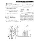
[0014] FIG. 1 is a schematically depicted cross section of a drive train having a centrifugal force pendulum situated between the an internal combustion engine and a friction clutch, and directly on a transmission input shaft,
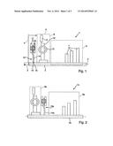
[0015] FIG. 2 is a schematically depicted cross section of a drive train having a centrifugal force pendulum situated between a friction clutch and a spur gear arrangement, and directly on a transmission input shaft,
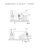
[0016] FIG. 3 is a schematically depicted cross section of a drive train having a centrifugal force pendulum integrated into a spur gear arrangement, and situated directly on a transmission input shaft,
[0017] FIG. 4 is a schematically depicted cross section of a drive train having a centrifugal force pendulum situated directly on the end of a transmission input shaft that faces away from the friction clutch, and
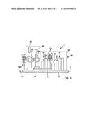
[0018] FIG. 5 is a schematically depicted cross section of a drive train having a dual-clutch transmission with two sub-transmissions, each sub-transmission having a separate transmission input shaft and each sub-transmission having a centrifugal force pendulum situated on the associated transmission input shaft.
DESCRIPTION OF THE PREFERRED EMBODIMENTS
[0019] FIG. 1 shows in schematic, cross-sectional form the upper half of a drive train 1, positioned around the axis of rotation 2, with an internal combustion engine, of which only the crankshaft 3 and the flywheel 4, which can be a single or a dual-mass flywheel, are shown. Situated on the transmission input shaft 5 is a spur gear arrangement 6, with several spur gears 7 for setting different gear ratios with complementary spur gears, not shown, that mesh with spur gears 7 and that are positioned on a transmission output shaft, also not shown. Friction clutch 8 with the clutch housing 9 and the clutch plate 10 are also situated on transmission input shaft 5. The clutch housing 9 receives the torque of the crankshaft 3 through the flywheel 4 and transmits it, independent of the engagement state of the friction clutch 8, through the friction linings 11 of the clutch plate 10 to the transmission input shaft 5, to which the clutch plate 10, which includes a torsional vibration damper 12, is connected in a rotationally locked manner.
[0020] In the exemplary embodiment shown in FIG. 1, the centrifugal force pendulum 13 is accommodated in the construction space between the flywheel 4 and the friction clutch 8, and is connected directly to the transmission input shaft 5 in a rotationally locked manner such as by a meshing connection. The pendulum flange 14 of the centrifugal force pendulum 13 receives the pendulum masses 17 by means of rollers 16 on both sides of pendulum flange 14, and by means of the internal teeth 15 meshes in a rotationally locked manner with the complementary external teeth 18 of the transmission input shaft 5. Alternatively, the pendulum flange 14 can be received on a hub (not shown), which, in turn, is connected to the transmission input shaft 5 in a rotationally locked manner such as by a meshing connection, and on which the pendulum flange 14 is received in a rotationally locked manner or with limited torque by interposing a slip clutch (not shown).
[0021] In contrast to drive train 1 of FIG. 1, FIG. 2 a drive train 1a, with a friction clutch 8a that is spaced from the spur gear arrangement 6a. In this case, the centrifugal force pendulum 13a is received with its pendulum flange 14a directly on the transmission input shaft 5a in the construction space between friction clutch 8a and spur gear arrangement 6a.
[0022] FIG. 3 shows, as a modification of drive trains 1, 1a of FIGS. 1 and 2, the drive train 1b, with a pendulum flange 14b of centrifugal force pendulum 13b received directly on transmission input shaft 5b. Centrifugal force pendulum 13b is positioned within spur gear arrangement 6b and--as shown--is positioned axially next to and upstream of the spur gears 7b on the transmission input shaft 5b. Alternatively, the centrifugal force pendulum 13b can be positioned between the spur gears 7b.
[0023] In a further modification, the drive train 1c of FIG. 4 is equipped--in contrast to the drive trains 1, 1a, 1b of FIGS. 1 through 3--with the centrifugal force pendulum 13c positioned directly on the transmission input shaft 5c on the downstream side of the spur gear arrangement 6c, the side of spur gear arrangement 6c that faces away from the friction clutch 8c. To that end, the transmission shaft 5c is extended axially to extend through the spur gear arrangement 6c, and receives the pendulum flange 14c of the centrifugal force pendulum 13c on the extended end 19 of transmission shaft 5c in a rotationally locked manner.
[0024] FIG. 5 shows a schematic cross-sectional depiction of the upper half of the drive train 1d positioned around the axis of rotation 2, which, in contrast to the drive trains 1, 1a, 1b, 1c of FIGS. 1 through 4, contains the spur gear arrangement 6d in the form of a dual-clutch transmission 20 including two sub-transmissons 21, 22, each having gear sets with spur gears 7d, 7e situated on separate transmission input shafts 5d, 5e. Accordingly, the dual clutch 8d is provided with the clutch plates 10d, 10e, which independently of each other transmit the torque that is transmitted from a crankshaft 3d to the housing 9d of the dual clutch 8d to the transmission input shafts 5d, 5e.
[0025] Transmission input shafts 5d, 5e are positioned coaxially to each other. To that end, the transmission input shaft 5e is designed as a hollow shaft 23 and is situated around the transmission input shaft 5d. Connected to each of the two transmission input shafts 5d, 5e is a respective centrifugal force pendulum 13d, 13e, which is connected to the respective transmission input shaft in a rotationally locked manner. In the depicted exemplary embodiment, the centrifugal force pendulum 13e carried on the hollow shaft 23 is positioned within the dual-clutch transmission 20. The depicted exemplary embodiment shows the centrifugal force pendulum 13e situated between the two sets of gears of the respective sub-transmissions 21, 22. The pendulum masses 17e of centrifugal force pendulum 13e lie radially outwardly of the nearest spur gear of the spur gears 7d having the smallest diameter. Depending on the design of the complementary spur gears (not shown) of the transmission input shaft, for example when designing the reverse gear, the nearest of the pendulum masses 17e can at least partially axially overlap the nearest of the spur gears 7d, for reasons of construction space.
[0026] In the depicted exemplary embodiment, the centrifugal force pendulum 13d assigned connected to the transmission input shaft 5d is positioned on the end of the transmission input shaft 5d between the dual-clutch 8d and the crankshaft 3d, with an inertial mass, such as a single-mass or dual-mass flywheel that can be situated on the latter.
User Contributions:
Comment about this patent or add new information about this topic:
Images included with this patent application:
 |  |
 |  |
| Similar patent applications: | |
| Date | Title |
|---|---|
| 2014-11-27 | Hybrid transportation apparatus having fuel cell and air engine |
| 2014-11-27 | Device for controlling automatic transmission and method for controlling same |
| 2014-11-27 | Apparatus for driving plug-in hybrid vehicle and method of controlling the same |
| 2014-11-27 | Hybrid drive of a motor vehicle and method for operating same |
| 2014-11-06 | Method for calibrating a detector in a damping assembly |
| New patent applications in this class: | |
| Date | Title |
|---|---|
| 2019-05-16 | Method for operating a drive train of a motor vehicle, and drive train module of a motor vehicle of this type |
| 2016-06-23 | Transmission |
| 2015-04-23 | Clutch mechanism, method for the operation of the clutch mechanism, as well as drive train of a motor vehicle |
| 2015-01-22 | Adjusting clutch slip based on sensed parameter of transmission shaft to control vehicle nvh |
| 2014-02-13 | Flywheel assembly for a powertrain |
| New patent applications from these inventors: | |
| Date | Title |
|---|---|
| 2021-07-01 | Drive unit for a drive train of an electrically driveable motor vehicle, and drive assembly and motor vehicle equipped with same |
| 2021-01-14 | Axially parallel hybrid module with chain drive and tensioning system |
| 2014-07-03 | Centrifugal pendulum and clutch disc having the latter |
| 2009-05-14 | Vibration damping assembly for a pulley that drives an auxiliary unit of a motor vehicle |
| 2008-12-25 | Drive wheel of an auxiliary unit belt drive of an internal combustion engine |
| Top Inventors for class "Interrelated power delivery controls, including engine control" | |
| Rank | Inventor's name |
|---|---|
| 1 | Alex O'Connor Gibson |
| 2 | Jeffrey Allen Doering |
| 3 | Atsushi Tabata |
| 4 | Seung-Hoon Lee |
| 5 | Anthony H. Heap |