Patent application title: ELECTRONIC CIGARETTE
Inventors:
Qiuming Liu (Shenzhen, CN)
Qiuming Liu (Shenzhen, CN)
IPC8 Class: AA24F4700FI
USPC Class:
131329
Class name: Tobacco tobacco users' appliance
Publication date: 2014-09-18
Patent application number: 20140261496
Abstract:
An electronic cigarette, comprising a tube body, a suction nozzle cover,
an oil-absorbing cotton and a supporting tube received in the tube body,
the supporting tube defines a center hole therein, the suction nozzle
cover includes a cover cap and a cover body, the cover cap defines at
least one smoking hole(s), the axial projection on the cover cap of the
smoking hole(s) partially overlaps or is separated from the axial
projection on the cover cap of the center hole of the supporting tube,
which makes the smoke flowing through the center hole of the supporting
tube to turn flow direction and is exhausted from the smoking hole(s) for
users to imbibe. So that smoke oil particles fixed in the smoke is
obstructed inside the electronic cigarette effectively, users are
prevented from imbibition of smoke oil particles, smoking taste and user
experience are improved accordingly.Claims:
1. An electronic cigarette, comprising: a tube body, a suction nozzle
cover, an oil-absorbing cotton and a supporting tube received inside the
tube body, the oil-absorbing cotton covered on an outer surface of the
supporting tube, a center hole defined in the supporting tube and
configured to guide smoke, wherein, the suction nozzle cover comprises a
cover cap covered on the tube body and a cover body extending along a
bottom surface of the cover cap and inserted into the tube body, the
cover cap defines at least one smoking hole(s) therein, an axial
projection on the cover cap of the smoking hole is separated from or
partially overlaps with an axial projection on the cover cap of the
center hole of the supporting tube, and the smoke flowing through the
center hole of the supporting tube is forced to turn and is exhausted
from the smoking hole for users to inhale.
2. According to the electronic cigarette of claim 1, wherein, the smoke outlet extends inwards the cover body along the cover cap, and the smoke hole is a through hole.
3. According to the electronic cigarette of claim 2, wherein, an axial projection on the cover cap of the center hole of the supporting tube is defined as a projection area on the cove cap of the center hole of the supporting tube, the smoking hole(s) is/are defined in an opening area formed between the peripheral edge of the projection area and the exterior edge of the cover cap, and the axial projection of the smoking hole is separated from the axial projection on the cover cap of the center hole of the supporting tube.
4. According to the electronic cigarette of claim 3, wherein, the opening area of the cover cap defines at least two smoking holes, and the smoking holes are all separated from each other.
5. According to the electronic cigarette of claim 4, wherein, the smoking hole(s) are all separated from each other and are positioned equidistantly in a same radial direction of the cover cap.
6. According to the electronic cigarette of claim 4, wherein, a total cross sectional area of parts of the smoking holes located on an outer surface of the cover cap is ranged from two square millimeter to six square millimeter.
7. According to the electronic cigarette of claim 1, wherein, shapes of the smoking holes includes at least one of circular, polygon and ellipse.
8. According to the electronic cigarette of claim 1, wherein, the cover cap and the cover body are formed integrally.
9. According to the electronic cigarette of claim 1, wherein, each smoke hole is a straight hole.
10. According to the electronic cigarette of claim 1, wherein, each smoke hole is an inclined hole.
11. According to the electronic cigarette of claim 10, wherein, each smoking hole corresponds to the oil-absorbing cotton.
12. According to the electronic cigarette of claim 10, wherein, the cover cap defines at least two inclined holes therein, and all of the inclined holes have a same angle of inclination relative to a centre line of the cover cap.
13. According to the electronic cigarette of claim 11, wherein, the angles of inclination relative to the centre line of the cover cap of each of the inclined holes is ranged from twenty degrees to forty degrees.
14. According to the electronic cigarette of claim 1, wherein, the cover body includes bulge(s) formed thereon, the tube body defines slot(s) corresponding to the bulge(s) therein, and the bulge(s) and the slot(s) form clip connection(s).
15. According to the electronic cigarette of claim 1, wherein, the cover body defines slot(s) therein, the tube body includes bulge(s) corresponding to the slot(s) thereon, the slot(s) and the bulge(s) form clip connection(s).
Description:
CROSS-REFERENCE TO RELATED APPLICATIONS
[0001] This application is a continuation of International Patent Application No. PCT/CN2013/072769, with an international filing date of Mar. 15, 2013, designating the United States, now pending. The contents of these specifications are incorporated herein by reference.
FIELD OF THE INVENTION
[0002] The present invention relates to the field of electronic heating products, and more particularly, to a type of electronic cigarette.
BACKGROUND OF THE INVENTION
[0003] Because domestic publicity of anti-smoking is intensified and the people's awareness of health are enhanced, electronic cigarettes, which serve as the substitute of traditional tobacco, have been more and more widely used. An existing electronic cigarette is comprised of a cigarette rod and a cigarette holder fixed together. The cigarette rod includes a battery therein, the cigarette holder includes an atomization device received therein, and the atomization device is electrically connected to cigarette rod. The cigarette holder further includes an oil cup received therein for accommodating tobacco juice. When a user start to smoke via the cigarette holder, the tobacco juice flows into the atomization device slowly, and an atomization wire of the atomizer absorbs the tobacco juice. A control circuit board detects electric current and controls the heating device positioned adjacent to the atomization wire to atomize the tobacco juice and generate smoke, and the smoke flows through the suction nozzle cover and is inhaled by users.
[0004] In the prior art, a smoke hole of electronic cigarette is generally defined in a center of a suction nozzle cover, when a user uses the electronic cigarette, the user may often imbibe smoke oil particles, which may cause the user to feel uncomfortable.
SUMMARY OF THE INVENTION
[0005] Aiming at aforementioned drawbacks in the prior art including the easily imbibing of tobacco tar particles in case of using the electronic cigarette, the objective of the present invention is to provide an electronic cigarette which is able to obstruct smoke oil particles therein.
[0006] The technical solution of the present invention is implemented by providing a type of electronic cigarette which comprises a tube body, a suction nozzle cover, an oil-absorbing cotton and a supporting tube received inside the tube body, the oil-absorbing cotton covered on an outer surface of the supporting tube, a center hole defined in the supporting tube and configured to guide smoke, wherein, the suction nozzle cover comprises a cover cap covered on the tube body and a cover body extending along a bottom surface of the cover cap and inserted into the tube body, the cover cap defines at least one smoking hole(s) therein, an axial projection on the cover cap of the smoking hole is separated from or partially overlaps with an axial projection on the cover cap of the center hole of the supporting tube, and the smoke flowing through the center hole of the supporting tube is forced to turn and is exhausted from the smoking hole for users to inhale.
[0007] In the electronic cigarette of the present invention, the smoke outlet extends inwards the cover body along the cover cap, and the smoke hole is a through hole.
[0008] In the electronic cigarette of the present invention, an axial projection on the cover cap of the center hole of the supporting tube is defined as a projection area on the cove cap of the center hole of the supporting tube, the smoking hole(s) is/are defined in an opening area formed between the peripheral edge of the projection area and the exterior edge of the cover cap, and the axial projection of the smoking hole is separated from the axial projection on the cover cap of the center hole of the supporting tube.
[0009] In the electronic cigarette of the present invention, the opening area of the cover cap defines at least two smoking holes, and the smoking holes are all separated from each other.
[0010] In the electronic cigarette of the present invention, the smoking hole(s) are all separated from each other and are positioned equidistantly in a same radial direction of the cover cap.
[0011] In the electronic cigarette of the present invention, a total cross sectional area of parts of the smoking holes located on an outer surface of the cover cap is ranged from two square millimeter to six square millimeter.
[0012] In the electronic cigarette of the present invention, shapes of the smoking holes includes at least one of circular, polygon and ellipse.
[0013] In the electronic cigarette of the present invention, the cover cap and the cover body are formed integrally.
[0014] In the electronic cigarette of the present invention, each smoke hole is a straight hole.
[0015] In the electronic cigarette of the present invention, each smoke hole is an inclined hole.
[0016] In the electronic cigarette of the present invention, each smoking hole corresponds to the oil-absorbing cotton.
[0017] In the electronic cigarette of the present invention, the cover cap defines at least two inclined holes therein, and all of the inclined holes have a same angle of inclination relative to a centre line of the cover cap.
[0018] In the electronic cigarette of the present invention, the angles of inclination relative to the centre line of the cover cap of each of the inclined holes is ranged from twenty degrees to forty degrees.
[0019] In the electronic cigarette of the present invention, the cover body includes bulge(s) formed thereon, the tube body defines slot(s) corresponding to the bulge(s) therein, and the bulge(s) and the slot(s) form clip connection(s).
[0020] In the electronic cigarette of the present invention, the cover body defines slot(s) therein, the tube body includes bulge(s) corresponding to the slot(s) thereon, the slot(s) and the bulge(s) form clip connection(s).
[0021] When implementing the electronic cigarette of the present invention, the following advantageous effects can be achieved: in the electronic cigarette of the present invention, as an axial projection on the cover cap of the smoking hole only partially overlaps with or is serrated from an axial projection on the cover cap of the center hole of the supporting tube, a flow direction of the atomized smoke needs to be changed, so that the smoke can be exhausted via the suction nozzle cover. At the same time, the smoke oil particles fixed in the smoke is unable to deviate from the original flow direction of the smoke and is obstructed inside the electronic cigarette effectively. In this way, users avoid from imbibing the smoke oil, and smoking taste and user experience are improved accordingly.
BRIEF DESCRIPTION OF THE DRAWINGS
[0022] The invention and technical solution will be illustrated with reference to accompanying drawings in the following. In the figures:
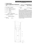
[0023] FIG. 1 is a partial cutaway view of the electronic cigarette in accordance with an embodiment of the present invention;
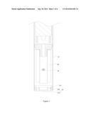
[0024] FIG. 2 is a structurally schematic view of the suction nozzle cover in accordance with a first embodiment of the present invention;
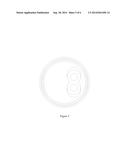
[0025] FIG. 3 is a schematic view of the suction nozzle cover shown along the orientation A of FIG. 2;
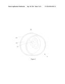
[0026] FIG. 4 is a structurally schematic view of the suction nozzle cover in accordance with a second embodiment of the present invention;
[0027] FIG. 5 is a schematic view of the suction nozzle cover shown along the orientation B of FIG. 4;
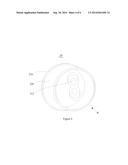
[0028] FIG. 6 is a partial cutaway view of the one-off atomization device in accordance with an embodiment of the present invention.
DETAILED DESCRIPTION OF THE PREFERRED EMBODIMENT
[0029] Specific implementations of the present invention is explained in detail in accordance with accompanying drawings so that the technical feature, objective and effect of the present invention can be understood more clearly.
[0030] As shown in FIG. 1, an electronic cigarette is illustrated in accordance with a preferred embodiment of the present invention, the electronic cigarette comprises a tube body 10, a suction nozzle cover 20, a supporting tube 30, and an oil-absorbing cotton 40. Wherein, the tube body 10 is approximately a hollow and cylinder-shaped structure and receives the suction nozzle cover 20, the supporting tube 30 and the oil-absorbing cotton 40 therein. The heating component passes through the through-hole of the supporting tube 30 traversely and is fixed inside the supporting tube 30, the oil-absorbing cotton 40 envelops an outer surface of the supporting tube 30, and a center hole configured for allowing smoke to flow in the electronic cigarette is defined in the supporting tube 30.
[0031] The suction nozzle cover 20 is approximately a hollow and cylinder-shaped structure, and is made of silica gel material and has excellent characteristics such as elasticity and corrosion resistance. It is understood that the suction nozzle cover 20 can also be made of flexible materials such as rubber.
[0032] The suction nozzle cover 20 comprises a cover cap 210 and a cover body 220. The cover body 220 extends along a bottom surface of the cover cap 210 and is sleeved in the tube body 10, the cover cap 210 covers the top of the tube body 10 so that the whole electronic cigarette is sealed up. The cover cap 210 and the cover body 220 of the suction nozzle cover 20 are formed integrally, and the integrated structure of the cover cap 210 and the cover body 220 is easy to process and excellent in an integrity effect.
[0033] For preventing the suction nozzle cover 20 from being ejected out of the tube body 10 and even being swallowed by users that are smoking, the suction nozzle cover 20 and the tube body 10 are set to establish a clip connection. A lateral wall of the cover body 220 includes one or a plurality of convex-shaped buckle(s) formed thereon (not shown), correspondingly, an inner wall of the tube body 10 defines slot(s) configured to establish the clip connection with the buckle(s). By the clip connection between the buckle(s) and the slot(s), the suction nozzle cover 20 is detachably mounted on a top of the tube body 10. In some other embodiments, it is understand that the latter wall of the cover body 220 defines the slot(s) therein (not shown), and the inner wall of the tube body 10 includes the buckle(s) formed thereon (not shown). By the clip connection between the slot(s) and the buckle(s), the tube body 10 and the suction nozzle cover 20 are detachably connected together.
[0034] As shown in FIG. 2, FIG. 3 and FIG. 4, the cover cap 210 defines at least one smoking hole(s) 212, the axial projection on the cover cap 210 of the smoking hole(s) 212 is separated from or partially overlaps with the axial projection on the cover cap 210 of the center hole of the supporting tube 30. Thus, the atomized smoke flowing into the smoking hole(s) 212 is unable to directly enter the smoking hole(s) 212 defined in the cover cap 210 via the center hole of the supporting tube 30, and needs to deviate from the original flow direction, so that the atomized smoke can enter the smoking hole(s) 212 and be exhausted to be inhaled by users. Smoke oil particles fixed in the smoke, which are unable to redirect the flow direction, are obstructed inside the electronic cigarette effectively, so that the amount of the smoke oil inhaled by users is reduced effectively, and user experience is improved. With respect to the embodiment of the present invention, the smoking hole(s) 212 extend(s) inwards the cover body 220 along the cover cap 210, and the smoking hole(s) 212 is (are) through-hole(s). The cover cap 210 defines two cylinder-shaped smoking holes 212 therein in the embodiment of the present invention, and the two cylinder-shaped smoking holes 212 are unspaced. A depth of each of the smoking holes 212 is greater than a thickness of the cover cap 210. Understandably, the depth of each of the smoking holes 212 can also be equal to or less than the thickness of the cover cap 210. When the depth of each of the smoking holes 212 is less than the thickness of the cover cap 210, the smoking holes 212 is a groove recessing inwards the cover cap 210. When a depth of each of the smoking holes 212 is equal to the thickness of the cover cap 210, the smoking hole(s) 212 pass(es) through the whole cover cap 210. The shapes of the smoking holes 210 includes at least one of triangle, polygon and ellipse, and the shapes of the polygon can include pentagon and hexagon and so on. Furthermore, there is no limitation to the number of the smoking holes 212 mentioned above, one or more smoking hole(s) 212 can be defined in the cover cap 210 in the embodiment of the present invention. Less smoke flow will be generated inside the electronic cigarette when the number of the smoking holes 212 is less, and more smoke flow will be generated when the number of the smoking holes 212 is larger.
[0035] The axial projection on the cover cap 210 of the center hole of the supporting tube 30 is defined as a projection area on the cover cap 210 of the center hole of the supporting tube 30, and the area formed between the peripheral edge of the projection area and the exterior edge of the cover cap 210 is defined as an opening area. When a part of the smoking holes 212 are located in the opening area, the axial projection on the cover cap 210 of the smoking holes 212 partially overlaps with the axial projection on the cover cap 210 of the center hole of the supporting tube 30. When the whole smoking holes 212 are located in the opening area, the axial projection on the cover cap 210 of the smoking holes 212 is separated from the axial projection on the cover cap 210 of the center hole of the supporting tube 30. Compared with the partial overlap case, when the axial projection on the cover cap 210 of the smoking holes 212 is separated from the axial projection on the cover cap 210 of the center hole of the supporting tube 30, the atomized smoke needs to turn a larger angle, so that the smoke can enter the smoking holes 212 and be inhaled by users. The smoke particles fixed in the smoke are unable to be exhausted from the smoking holes 212 because of their inability of deviating from the original flow direction, as a result, users are prevented from imbibing the smoke oil particles effectively, and the smoking taste is improved. Therefore, the smoking effect under the circumstance of total separation is better than the smoking effect under the circumstance of partial overlap in regard to the axial projection mentioned above.
[0036] When the cover cap 210 defines at least two smoking holes 212, the smoking holes 212 can be separated from each other. Particularly, the smoking holes 212 can be separated from each other equidistantly or not equidistantly. One lateral of the cover cap 210 that is adjacent to the cover body 220 is defined as an inner surface of the cover cap 210, and the other lateral of the cover cap 210 that is away from the cover body 220 is defined as an outer surface of the cover cap 210. A total cross sectional area of all of the smoking holes 212 is ranged from two square millimeters to six square millimeters. If the total cross sectional area is less than two square millimeters, the smoke may be obstructed and accumulated inside the electronic cigarette, which may cause damage to the electronic cigarette. If the total cross sectional area is more than six square millimeters, a large quantity of smoke flow will be generated, which may adversely affect the smoking taste. Correspondingly, a diameter of an opening of each smoking hole 212 formed in the outer surface of the cover cap 212 should be ranged from 0.3 millimeter to 1.4 millimeters.
[0037] It is understand that the smoking holes 212 can also be unspaced from each other. It is preferred that all of the smoking holes 212 can also be defined in the opening area and positioned in a same radial direction of the cover cap 210, so that a circular loop convenient for smoke flow is formed accordingly.
[0038] As shown in FIG. 2 and FIG. 3, in a first embodiment of the present invention, two smoking holes 212 are defined, and each smoking hole 212 is a straight hole. A diameter of each of the two smoking holes 212 is 0.85 millimeter. The two smoking holes 212 are unspaced from each other and form a figure-8 shape.
[0039] As shown in FIG. 4 and FIG. 5, in a second embodiment of the present invention, two smoking holes 212 are defined, and each of the two smoking holes 212 is an inclined hole. The two smoking holes 212 are unspaced from each other and form a figure-8 shape. Preferably, when two or more smoking holes 212 are defined, each of the smoking holes 212 has a same inclined angle ranging from twenty degrees to forty degrees relative to the center line of the cover cap 210. The inclined angle is thirty degrees in this embodiment of the present invention.
[0040] The smoking holes 212 incline obliquely and downward from the cover cap 210 to the cover body 220, and each of the smoking holes 212 corresponds to the oil-absorbing cotton 40, which makes the smoking holes 212 be separated from the center hole of the supporting tube 30 completely. In this way, smoke in the center hole of the supporting tube 30 needs to deviate from an original flow direction and turn toward the orientation of the inclined holes, the smoke can enter the smoking holes 212 and be inhaled by users. Smoke oil particles fixed in the smoke are unable to change original flow direction, and is unable to enter the smoking holes 212, so that users are prevented from imbibition of the smoke oil particles effectively. It is understand that the part of each of the smoking holes 212 that is away from the center hole of the supporting tube 30 can be defined anywhere of the cover cap 210, and the effectiveness of the present invention won't be adversely affected.
[0041] The two embodiments mentioned above are merely demonstration instead of limitation, there are some other options in regard to the number, the shape and the connection relationship of the smoking holes 212.
[0042] In the electronic cigarette of the present invention, as the axial projection on the cover cap 210 of the smoking holes 212 partially overlaps with or is separated from the axial projection on the cover cap 210 of the center hole of the supporting tube 30, the atomized smoke needs to deviate from an original flow direction to some extent, so that the smoke is enabled to be exhausted from the suction nozzle cover 20. Smoke particles fixed in the smoke is unable to change the flow direction, and is obstructed inside the electronic cigarette effectively. Thus users are prevented from imbibing smoke oil particles, and the smoking taste and user experience are improved as well.
[0043] As shown in FIG. 6, a type of one-off atomization device is provided in the present invention, which comprises a tube body 610, a suction nozzle cover 620 and a supporting tube 630. The suction nozzle 620 defines at least one smoking hole(s) 622, and the smoking hole(s) 622 may be any one of the above-mentioned smoking hole(s) 212.
[0044] The embodiments of the present invention are described according to the accompanying figures, however, the present invention shall not be limited to the above-mentioned embodiments which are only considered as some demonstrations instead of limitation to the present invention. Lots of modalities can be made by the one skilled in the art with the help of the inspiration from the present invention without breaking away from the principle and scope of protection of the claims, wherein these modalities are within the scope protected by the present invention.
User Contributions:
Comment about this patent or add new information about this topic:
Images included with this patent application:
 |  |
 |  |
 |  |
 |
| Similar patent applications: | |
| Date | Title |
|---|---|
| 2015-05-14 | Electronic cigarette |
| 2015-05-14 | Electronic cigarette |
| 2015-05-21 | Electronic cigarette and electronic cigarette device |
| 2015-05-21 | Electronic cigarette |
| 2014-12-04 | Electronic cigar |
| New patent applications in this class: | |
| Date | Title |
|---|---|
| 2022-05-05 | Aerosol delivery device having a resonant transmitter |
| 2022-05-05 | Aerosol generating device and operating method therefor |
| 2022-05-05 | Electronic smoking device |
| 2022-05-05 | Flavor dispenser apparatus |
| 2022-05-05 | Electronic cigarette atomization assembly and manufacturing method therefor |
| New patent applications from these inventors: | |
| Date | Title |
|---|---|
| 2017-05-18 | Atomization assembly and electronic cigarette |
| 2017-02-16 | Method and system for searching for electronic cigarette of same type |
| 2017-02-16 | Electronic cigarette |
| 2015-12-10 | Electronic cigarette and method for adjusting flow rate of gas flow of electronic cigarette |
| 2015-10-08 | Atomizer and electronic cigarette |
| Top Inventors for class "Tobacco" | |
| Rank | Inventor's name |
|---|---|
| 1 | Qiuming Liu |
| 2 | Munmaya K. Mishra |
| 3 | Qiuming Liu |
| 4 | Stephen Benson Sears |
| 5 | William R. Sweeney |