Patent application title: SERVER CABINET
Inventors:
Zheng-Heng Sun (New Taipei, TW)
Zheng-Heng Sun (New Taipei, TW)
Assignees:
HON HAI PRECISION INDUSTRY CO., LTD.
IPC8 Class: AH05K718FI
USPC Class:
361724
Class name: Housing or mounting assemblies with diverse electrical components for electronic systems and devices cabinet-type housing
Publication date: 2014-07-03
Patent application number: 20140185246
Abstract:
A server cabinet includes a rack, a server, a switch, and a first
supporting member. The rack includes two columns located at a front end
of the rack. The server is installed between the columns. The switch is
installed in the rack above the server. Opposite ends of a front side of
the switch are fastened to the columns of the rack. The first supporting
member includes a connecting plate mounted to a rear side of the switch,
and a supporting plate extending out from an end of the connecting plate
and located below the switch. A raised portion protrudes down from the
supporting plate. The raised portion is supported on the server.Claims:
1. A server cabinet, comprising: a rack comprising two columns located at
a front end of the rack; a server installed between the columns; a switch
installed in the rack and above the server, a front side of the switch
fastened to the columns of the rack; and a first supporting member
comprising a connecting plate mounted to a rear side of the switch, and a
supporting plate extending out from an end of the connecting plate and
located below the switch, a raised portion protruding down from the
supporting plate, wherein the raised portion is supported on the server.
2. The server cabinet of claim 1, further comprising two second supporting members connected between the columns and two opposite sides of the front side of the switch, each second supporting member comprises a connecting plate fixed to the switch, and a supporting plate extending out from the connecting plate and installed to the corresponding column.
3. The server cabinet of claim 2, wherein each end of the switch defines a screw hole, the connecting plate of each second supporting member defines a connecting hole, a screw extends through the connecting hole and is screwed into the screw hole of the switch.
4. The server cabinet of claim 2, wherein the supporting plate of each second supporting member defines two through holes, two screws extend through the through holes and are screwed into the column.
5. The server cabinet of claim 1, wherein the rear side of the switch defines a screw hole, the connecting plate of the first supporting member defines a connecting hole, a screw extends through the connecting hole of the first supporting member and is screwed in the screw hole of the switch.
Description:
BACKGROUND
[0001] 1. Technical Field
[0002] The present disclosure relates to a server cabinet.
[0003] 2. Description of Related Art
[0004] In a server cabinet, a front end of a switch is generally fastened to a rack of the cabinet by screws. However, if the switch is long and heavy, a rear end of the switch may tilt and damage the bonding by screws between the front end of the switch unit and the cabinet.
BRIEF DESCRIPTION OF THE DRAWINGS
[0005] Many aspects of the present embodiments can be better understood with reference to the following drawings. The components in the drawings are not necessarily drawn to scale, the emphasis instead being placed upon clearly illustrating the principles of the present embodiments. Moreover, in the drawings, all the views are schematic, and like reference numerals designate corresponding parts throughout the several views.
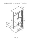
[0006] FIG. 1 is an exploded, isometric view of an exemplary embodiment of a server cabinet, wherein the server cabinet includes a plurality of supporting members.
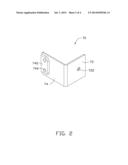
[0007] FIG. 2 is an enlarged view of one of the supporting members of FIG. 1.
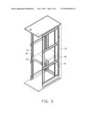
[0008] FIG. 3 is an assembled, isometric view of the server cabinet of FIG. 1.
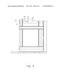
[0009] FIG. 4 is a side plan view of FIG. 3.
DETAILED DESCRIPTION
[0010] The disclosure, including the accompanying drawings, is illustrated by way of example and not by way of limitation. It should be noted that references to "an" or "one" embodiment in this disclosure are not necessarily to the same embodiment, and such references mean at least one.
[0011] FIG. 1 and FIG. 2 show an exemplary embodiment of a server cabinet. The server cabinet includes a rack 10, a server 30, a switch 50, and four supporting members 70.
[0012] The rack 10 includes a rectangular base 12, four vertical columns 14 located at four corners of the base 12, and a top wall 124 supported on top ends of the columns 14. Each column 14 defines a plurality of positioning holes 142 arrayed along a lengthwise direction of the column 14. The server 30 is installed among the columns 14.
[0013] The switch 50 includes a bottom wall 51, a front wall 53 perpendicularly extending up from a front side of the bottom wall 51, a rear wall 54 perpendicularly extending up from a rear side of the bottom wall 51 opposite to the front wall 53, and two end walls 55 extending up from two opposite ends of the bottom wall 51 and connected between the front wall 53 and the rear wall 54. Each sidewall 55 defines two screw holes 52 respectively adjacent to the front wall 53 and the rear wall 54.
[0014] Each supporting member 70 includes a connecting plate 72 and a supporting plate 74 perpendicularly extending from an end of the connecting plate 72. A raised portion 742 protrudes out from an end of the supporting plate 74 away from the connecting plate 72. The raised portion 742 defines two through holes 744. A middle of the connecting plate 72 defines a connecting hole 722.
[0015] FIG. 3 and FIG. 4 show in assembly. Outer surfaces of the connecting plates 72 of two supporting members 70 opposite to the supporting plates 74 are abutted against the end walls 55 of the switch 50 adjacent to the front wall 53, to allow the supporting plate 74 of each supporting member 70 coplanar with the front wall 53. Two screws extend through the connecting holes 722, to be screwed into the corresponding screw holes 52 adjacent to the front wall 53. Therefore, the two supporting members 70 are adjacent to the front wall 53 of the switch 50. Inner surfaces of the connecting plate 72 of the other two supporting members 70 facing the supporting plates 74 are abutted against the end walls 55 adjacent to the rear wall 54, to allow inner surfaces of the supporting plates 74 facing the connecting plates 72 to abut against the bottom wall 51. Two screws extend through the connecting holes 722, to be screwed into the corresponding screw holes 52 adjacent to the rear wall 54. Therefore, the other two supporting members 70 are adjacent to the rear wall 54 of the switch 50.
[0016] A combination of the switch 50 and the supporting members 70 is installed to the rack 10. The rear wall 54 of the switch 50 is inserted into the rack 10 from a front end of the rack 10. The switch 50 is slid rearward on the server 30 until the supporting plates 74 of the two supporting members 70 adjacent to the front wall 53 abut against the columns 14. The raised portions 742 of the other two supporting members 70 are sandwiched between the switch 50 and the server 30. Four screws extend through the through holes 744, to be screwed into the corresponding positioning holes 142. The front side of the switch 50 is mounted to the front end of the rack 10 through the two supporting members 70, and the rear end of the switch 50 is supported on the server 30 through the raised portions 742 of the other two supporting members 70.
[0017] Even though numerous characteristics and advantages of the embodiments have been set forth in the foregoing description, together with details of the structure and the functions of the embodiments, the disclosure is illustrative only, and changes may be made in details, especially in the matters of shape, size, and arrangement of parts within the principles of the embodiments to the full extent indicated by the broad general meaning of the terms in which the appended claims are expressed.
User Contributions:
Comment about this patent or add new information about this topic:
| People who visited this patent also read: | |
| Patent application number | Title |
|---|---|
| 20170176714 | Focus Monitoring Arrangement and Inspection Apparatus Including Such an Arrangement |
| 20170176713 | ELECTRONIC APPARATUS |
| 20170176712 | LENS APPARATUS |
| 20170176711 | LENS BARREL AND IMAGING DEVICE |
| 20170176710 | VOICE COIL MOTOR |
Images included with this patent application:
 |  |
 |  |
 |
| Similar patent applications: | |
| Date | Title |
|---|---|
| 2013-06-27 | Server cabinet |
| 2013-11-21 | Server cabinet |
| 2013-11-21 | Server cabinet |
| 2014-03-20 | Server cabinet |
| 2014-03-27 | Server cabinet |
| New patent applications in this class: | |
| Date | Title |
|---|---|
| 2019-05-16 | Accommodation box and electronic component unit |
| 2016-12-29 | Wireless access device isolation cabinet |
| 2016-06-23 | Docking station |
| 2016-05-19 | Pivoting equipment mounting bracket |
| 2016-05-12 | Electronic device |
| New patent applications from these inventors: | |
| Date | Title |
|---|---|
| 2015-07-02 | Mounting apparatus for hard disk drive |
| 2015-01-22 | Server and indicating tag of the same |
| 2014-11-13 | Mounting device for fan |
| 2014-10-30 | Circuit board mounting apparatus |
| 2014-10-30 | Mounting device for hard disk drive |
| Top Inventors for class "Electricity: electrical systems and devices" | |
| Rank | Inventor's name |
|---|---|
| 1 | Zheng-Heng Sun |
| 2 | Levi A. Campbell |
| 3 | Li-Ping Chen |
| 4 | Robert E. Simons |
| 5 | Richard C. Chu |