Patent application title: Apparatus for Collecting a Representative Fluid Sample
Inventors:
Cyrus Aspi Irani (Houston, TX, US)
Cyrus Aspi Irani (Houston, TX, US)
Theodore Darius Irani (Austin, TX, US)
IPC8 Class: AE21B4908FI
USPC Class:
166 664
Class name: Wells with electrical means electrical motor (e.g., solenoid actuator)
Publication date: 2014-07-03
Patent application number: 20140182836
Abstract:
An apparatus for collecting a fluid sample from a reservoir contains a
sample gathering chamber, a motor driven hydraulic pump, a motor
mechanically coupled to the hydraulic pump, an electronic controller for
influencing the actions of the motor, and a power source for running the
motor. A piston which is sealably and movably disposed may be located
within a tubular portion defining the sample gathering chamber. The
apparatus may also further contain a metering component for regulating
pressure.Claims:
1. (canceled)
2. (canceled)
3. (canceled)
4. (canceled)
5. (canceled)
6. (canceled)
7. (canceled)
8. (canceled)
9. (canceled)
10. (canceled)
11. (canceled)
12. (canceled)
13. (canceled)
14. (canceled)
15. (canceled)
16. (canceled)
17. (canceled)
18. (canceled)
19. (canceled)
20. (canceled)
21. A system for sampling a subterranean reservoir fluid, the system comprising: (a) a subterranean reservoir fluid inlet port; (b) a tubular portion; (c) a piston sealably and movably disposed within the tubular portion, wherein the area in front of the piston and the subterranean reservoir fluid inlet port define a sample gathering chamber and further wherein the volume of the sample gathering chamber is expandable by lateral movement of the piston during collection of the subterranean reservoir fluid and lateral movement of the piston is reversible for compressing the collected subterranean reservoir fluid; (d) a space for a working fluid defined by the back of the piston and one or more surfaces of the tubular portion; (e) a metering section encased within the tubular portion and having a restrictive passage for regulating the movement of the working fluid; (f) a motor mechanically coupled to a hydraulic pump, wherein the motor and hydraulic pump are incorporated within the tubular portion and are positioned such that the working fluid may be pressurized after collection of the subterranean reservoir fluid and further wherein the motor is capable of being rotated in one direction during collection of the subterranean reservoir fluid and the opposite direction during compression of the collected subterranean reservoir fluid; (g) a power source for running the motor; and (h) an electronic controller for controlling the movement of the motor in order to maintain pressure within the system.
22. The system of claim 21, further comprising a trigger for controlling collection of the subterranean reservoir fluid within the sample gathering chamber through the subterranean reservoir fluid inlet port.
23. The system of claim 21, further comprising a pressure monitoring device.
24. The system of claim 21, wherein the power source is a battery pack.
25. The system of claim 24, wherein the battery pack is rechargeable or contains non-rechargeable cells.
26. The system of claim 21 wherein the electronic controller is pre-programmable.
27. The system of claim 21, further comprising a gearbox for magnifying the torque generated by the motor.
28. (canceled)
29. (canceled)
30. (canceled)
31. (canceled)
32. (canceled)
33. (canceled)
34. (canceled)
35. (canceled)
36. (canceled)
37. (canceled)
38. (canceled)
39. A sampling apparatus for sampling a subterranean reservoir fluid, the sampling apparatus comprising: (a) a subterranean reservoir fluid inlet port; (b) a tubular portion; (c) a piston sealably and movably disposed within the tubular portion, wherein the area in front of the piston, the tubular portion and the subterranean reservoir fluid inlet port define a sample gathering chamber; (d) a space on the side of the piston opposite the fluid inlet port for a working fluid; (e) a motor mechanically coupled to a hydraulic pump and positioned within the tubular portion such that the working fluid may be pressurized; (f) a power source within the tubular portion for running the motor; and (g) an electronic controller for controlling the movement of the motor in order to maintain pressure within the system.
40. A system for sampling a subterranean reservoir fluid, the system comprising: (a) an inlet port for collecting samples of the subterranean reservoir fluid within a sample gathering chamber; (b) a tubular portion; (c) a piston sealably and movably disposed within the tubular portion, wherein the area in front of the piston and the subterranean reservoir fluid inlet port defines the sample gathering chamber and further wherein the volume of the sample gathering chamber is expandable by lateral movement of the piston during collection of the subterranean reservoir fluid and further wherein lateral movement of the piston is reversible for compressing the collected subterranean reservoir fluid; (d) a motor mechanically coupled to a hydraulic pump and capable of repeatedly pressurizing samples of the subterranean reservoir fluid while being collected within the sample gathering chamber above the pressure at which the samples are collected, wherein the motor and hydraulic pump are within the tubular portion; and (e) a power source within the tubular portion for running the motor.
41. The sampling apparatus of claim 39, wherein the power source is a battery pack.
42. The sampling apparatus of claim 41, wherein the battery pack is rechargeable or contains non-rechargeable cells.
43. The sampling apparatus of claim 39, wherein the power source is an electrical cable.
44. The sampling apparatus of claim 40, further comprising a set of gears within the tubular portion for the motor mechanically coupled to the hydraulic pump.
45. The system of claim 24, wherein each of the hydraulic pump, the motor and the battery pack have passages for entry of the working fluid.
46. A sampling apparatus for sampling a subterranean reservoir fluid wellbore, the sampling apparatus comprising: (a) a fluid inlet port and a tubular portion; (b) a piston sealably and movably disposed within the tubular portion, wherein one or more surfaces of the piston and the tubular portion in conjunction with the fluid inlet port define a sample gathering chamber; (c) a space for a working fluid opposite the side of the piston defining the sample gathering chamber; (d) a pump positioned within the tubular portion such that fluid intake into the pump is located on the low pressure side of the working fluid space; (e) a motor mechanically positioned within the tubular portion and coupled to the pump; (f) an electronic controller for activating the motor and pump by the differential pressure on the working fluid space; and (g) a power source positioned within the tubular portion for running the motor.
47. The sampling apparatus of claim 46, further comprising a pressure monitoring device.
48. The sampling apparatus of claim 46, further comprising a gearbox for magnifying torque generated by the motor.
49. The sampling apparatus of claim 46, wherein the power source is a battery pack.
50. The sampling apparatus of claim 49, wherein the battery pack is rechargeable or contains non-rechargeable cells.
51. The sampling apparatus of claim 46, further comprising an electronic controller capable of controlling the movement of the motor in order to maintain pressure within the tubular portion.
Description:
TECHNICAL FIELD OF THE INVENTION
[0001] This invention relates, in general, to equipment utilized in conjunction with operations performed in relation to subterranean wells and, in particular, to a sampler for collecting and recovering a representative fluid sample from a subterranean formation of interest.
BACKGROUND OF THE INVENTION
[0002] Without limiting the scope of the present invention, its background will be described in relation to exploratory subterranean well operations, as an example.
[0003] As used herein, the words "comprise", "have", "include", and all grammatical variations thereof are each intended to have an open, non-limiting meaning that does not exclude additional elements, steps, or embodiments. Furthermore, it should be understood that as used herein, "first", "second", "third", etc. are arbitrarily assigned and are merely intended to differentiate between two or more elements, devices, embodiments, etc., as the case may be, and does not indicated a specific sequence, nor should be viewed as a limiting sequence. Furthermore, it is to be understood that the mere use of the term "first" does not automatically imply that it should be followed by a "second" or for that matter a "second by a "third".
[0004] As used herein, the phrases "hydraulically coupled," "hydraulically connected," "in hydraulic communication," "fluidly coupled," "fluidly connected," and "in fluid communication" refer to a form of coupling, continuum, connection, or communication related to fluids, and the corresponding transmission of flows or pressures associated with these fluids. In some embodiments, a hydraulic coupling, connection, or communication between two components describes components that are associated in such a way that fluid pressure may be equally transmitted between or among the components. Reference to a fluid coupling, connection, or communication between two components describes components that are associated in such a way that a fluid can easily flow between or among the components. Hydraulically coupled, connected, or communicating components may include certain arrangements where fluid does not flow between the components, but fluid pressure may nonetheless be transmitted across an interface such as a diaphragm or piston.
[0005] As used herein, a "fluid" is a substance having a continuous phase that tends to flow and to confirm to the boundaries of the vessel containing it. A fluid can display the properties of a liquid or a gas, depending on where, based on its composition, temperature and pressure, it falls on the gas-liquid continuum.
[0006] From simple beginnings, the search for oil reserves has moved into more remote locations and more technically demanding reservoirs and environments. Exploratory wells are often drilled with the goal of finding new hydrocarbon reserves, identifying the nature of the reserves, and then verifying their economic viability. Consequently, after a well has been drilled and underground hydrocarbon bearing strata have been identified, it is desirable to determine the physical characteristics of the strata in question and also the chemical characteristics of the hydrocarbon in place. The physical characteristics provide invaluable clues as to the extent of the reservoir and how fast it can be made to produce its hydrocarbon content. The chemical characteristics are invaluable in defining the monetary value of the hydrocarbon reserves as also the best mechanism by which the recovered reserves can be handled and further processed. Both the physical and chemical characteristics are invaluable pieces of information for defining the monetary value that can be assigned to a prospective discovery.
[0007] Numerous pieces of equipment and methodologies are available and well known to those active in the industry for determining the physical properties of a reservoir. These include the extensive suite of tools available during Measurement while Drilling (MWD) operations, Logging While Drilling (LWD) operation, Wireline Formation Testing (WFT) operations, Production Logging (PL) operation, and Surface Well Testing (SWT) operations, including methodologies such as pressure drawdown testing, gamma-ray logging, neutron density logging, MRI logging, etc. For the sake of brevity these will not be further discussed, though an absence to do so should not be viewed as a limitation to this disclosure.
[0008] A detailed understanding of the reservoir fluid including its chemical description may be viewed as perhaps the most significant aspect of any well test operation. A sample of the reservoir fluid is invaluable for undertaking a detailed laboratory PVT analysis, where the initials PVT stand for Pressure, Volume, and Temperature. A representative reservoir sample is also crucial for generating a detailed chemical analysis of the hydrocarbon phase. For these and many other reasons it should be readily apparent to those familiar with the oil industry that collecting and recovering a representative sample of reservoir fluid is a crucial first step in defining the economic viability of a newly discovered hydrocarbon reservoir.
[0009] There are a number of opportunities during the exploratory and production cycle when a reservoir sample can be collected. Recent technological developments have made it possible for hydrocarbon samples to be collected as early as the drilling phase. During drilling operations samples can be collected in samplers associated with the drill string. After the conclusion of the drilling phase and while the drilled borehole is still an open hole, namely exposed formation rock, samples can be collected during traditional Wireline Formation Testing (WFT) operations. During WFT a number of tools directed at delivering a better understanding of the physical and chemical nature of the reservoir are introduced into the borehole via wireline. Included in this tool string is a set of samplers for collecting bottomhole samples.
[0010] Once casing is set and the openhole is cemented, a Drill Stem Test or DST can be undertaken. During a DST operation samples can be collected on pipe or tubing by incorporating carriers specifically designed for carrying a multiplicity of samplers from the surface to the subterranean zone of interest on the work string. A cased hole environment also affords numerous opportunities to run a set of production logging tools on e-line or wireline. and offers another excellent opportunity to collect samples of the reservoir fluids. Stand alone slickline or e-line sampling is also feasible in a cased hole environment.
[0011] The sample collecting process itself is complicated and requires a number of distinct and necessary steps. First a subterranean zone of interest needs to be identified that would warrant the expense of undertaking a sampling operation. Next some means needs to be identified for locating a sampler adjoining to or in the vicinity of the zone in interest. With the sampler at location some mechanism is needed to trigger the sampler to collect a sample at the correct instance during some specific static or flow period appropriate to the testing being undertaken of the subterranean zone of interest. Once the sampler is triggered the sample should be collected in a controlled fashion so as to minimize the possibility of the sample flashing two phase. Once the sample collection has been completed, the sample has to be locked in place in the sampler, and simultaneously a high pressure charge of gas, usually nitrogen, is released against the sample to exert pressure on the sample and keep it single phase during recovery to the surface. At the surface the sample is usually transferred, again at high temperature and pressure, into long term storage bottles.
[0012] Recognizing the need to preserve the sample single phase and at some high pressure after collection, it should be obvious that equal precautions need to be taken during the collection of the sample. Consequently, all samplers designed to collect a single phase sample are also designed to collect the sample at a pressure that is as close as possible to the pressure of the reservoir where the fluid to be sampled resides. Furthermore, as most samples are collected ahead of a moving piston located in a tubular section, preserving the integrity of the sample during the collection phase requires that the movement of the piston be slowed down to prevent the sample from flashing two phase the instant the sampler's tubular section is exposed to the high pressure fluid phase to be sampled.
[0013] Slowing the movement of the sample collecting piston is most easily accomplished by the simple expediency of incorporating some non-interacting fluid, usually referred to as a displacement fluid, on the backside of the sampling piston, namely the side opposite to where the sample will collect. As a consequence, as the sample enters the tubular section on one side of the sample piston causing it to be laterally displaced, this lateral movement of the piston will result in a corresponding lateral movement of the displacement fluid. If the lateral movement of the displacement fluid is further constrained by forcing it through a very fine constriction or choke, then the resulting very slow movement of the sampling piston due to the restriction of the movement of the displacement fluid is successful in delivering a single phase sample at reservoir pressure, where flashing has been minimized or even eliminated.
[0014] Furthermore, it should be readily obvious to one familiar with the art that the very presence of the displacement fluid will require that the sampler be equipped with some low pressure dump chamber into which the displacement fluid can be ejected while the sample is being collected, and where the displacement fluid will stay stored during the entire sample collection, recovery to the surface, and subsequent storage until such time that the sample is transferred out of the sampler for further analysis. It is significant that once the displacement fluid moves through the choke or metering section and into the dump chamber, it has completed its function and is now redundant.
[0015] A sample that is successfully captured downhole is subject to significant thermal gradients during subsequent recovery to the surface. Invariably a sample is collected at some temperature higher than, and usually much higher than ambient. During recovery to the surface it follows that the temperature of the sample must decrease until it reaches equilibrium with the ambient temperature. This temperature drop during the recovery step causes the sample to shrink in volume, and if the volume of the container with sample in it does not change, this shrinkage of the sample causes the sample pressure to drop. If the sample pressure should approach, or fall below the saturation pressure, the sample will go two phase with gas breaking out, or even multi phase with gas and solid breaking out, at which point the sample is no longer considered representative. Depending on the particular circumstance, when the sample goes multi-phase, considerable effort and expense will need to be expended to return it to a representative monophasic state.
[0016] In order to mitigate the detrimental effects of shrinkage it has proven necessary in the past that a collected sample be immediately brought in contact with a high pressure nitrogen charge in order to bring the sample pressure up to some desirable value adequate for the sample to stay single phase during recovery to the surface and subsequent transportation and storage. Consequently, each sampler must be connected to a high pressure nitrogen source, to which end each sampler can have its own nitrogen source, which is by far the more prevalent design, or, as is seen in some very unique cases, there can be a common nitrogen source for more than one, or even all the samplers. Irrespective of the exact design, it is imperative that the pressure and volume of the nitrogen source be such that it will successfully maintain the sample pressure at least 2000 psi above and preferably even higher than the pressure at which the sample was collected, and maintain this high pressure during the entire subsequent history of the sample.
[0017] To reiterate, a successful sampling operation requires some receptacle rated for high pressure and temperature service and equipped with a plurality of associated chambers and mechanisms such that when said receptacle is brought alongside a subterranean formation of interest and triggered or activated, it will allow the fluid contained in the subterranean formation of interest to enter and gather in the appropriate chamber associated with the receptacle. Furthermore, the entry of the said reservoir fluid into the said chamber is deliberately controlled by the slow drainage of a displacement fluid from a chamber adjoining the chamber receiving the sample into some immediately or closely associated chamber specifically included for the purpose of receiving the displacement fluid. The controlled movement of the displacement fluid is most effectively implemented by forcing the displacement fluid to flow through a restrictive choke as it transitions between the two afore mentioned chambers. Once the sample has been collected it is necessary that the sample be locked in place to trap it so it is contained for further transportation and handling. Simultaneously, a source of high pressure gas, preferably nitrogen, contained in a chamber either adjoining the sample chamber or in close proximity to the sample chamber, is brought in indirect communication with the collected sample so as to take the pressure of the sample to at least 2000 psi above the pressure at which it was collected and keep it at this high pressure during the subsequent recovery to the surface.
[0018] All of this requires a number of intricate parts that must work in precise unison if the sampling step is to be successful. Consequently, it should be obvious to one well versed in the sampling art that there is a need for a sampler of simpler design that is easier and safer to operate and would deliver a more reliable performance than is presently available.
SUMMARY OF THE INVENTION
[0019] The present invention disclosed herein is directed to a sampling apparatus for collecting and preserving a representative sample of a subterranean reservoir fluid. Additionally, the proposed design has the flexibility and versatility to function effectively in numerous subterranean environments and applications including open hole and cased hole situations. Furthermore, the proposed design has the flexibility and versatility to function effectively when conveyed to the subterranean formation of interest by any of a number of means. The means of conveyance may include slickline, wireline, e-line, coiled tubing, pipe, tubing, etc. The proposed design also has the flexibility to deliver a representative sample irrespective of the fluid or hydrocarbon type encountered.
[0020] Additionally, the proposed design is unique in that it eliminates the need for a high pressure nitrogen source resulting in a much simpler, safer, and more compact device. Furthermore, the uniqueness of the design delivers samplers with much higher recovery pressures relative to the more conventional design using a nitrogen charge.
[0021] To achieve the above stated objectives the method of the present invention will incorporate an appropriately sized electrical motor into the body of the sampler. The power needed to run the electrical motor will come from either an adjoining battery pack or an attached electrical cable if the sampling operation is being undertaken using wireline or e-line. The electrical motor in turn will drive a hydraulic pump, either directly or through the agency of a set of gears, with the resulting output of the hydraulic pump being a pressurized hydraulic fluid. The pressurized hydraulic fluid in turn can be brought to bear on the non-sample side of sample collecting piston to exert pressure on the sample collecting piston, and subsequently pressure on the sample itself. By this simple expediency the need for the cumbersome and dangerous nitrogen source is eliminated. Furthermore, the very nature of the mechanism being exploited is guaranteed to deliver a higher and more reliable recovery pressure than would be delivered by the existing nitrogen source.
[0022] Associated with the electric motor and in electrical communication with would be control electronics such as processor devices, data storage devices, and communication devices, or alternatively, a centralized control unit may be provided that communicates with and controls one or more of the individual components that comprise the aforementioned sampler. The purpose of the control electronics is to provide instructions to the electrical motor to define exactly how and when the motor is to function. For example, with programmable control electronics, instructions provided either as input at the surface and stored in memory associated with the control electronics before start of sampling operations, or transmitted during sampling operations either via an optical cable, or an electrical cable, or as an acoustic signal from the surface to an appropriate receiver in or in the vicinity of the control electronic, would provide instructions on the direction, speed and duration that the electrical motor should run in order to provide some necessary function associated with the sampling process.
[0023] In operation, the sampler would be positioned at the subterranean formation of interest via one of the methods of conveyances mentioned above. When so positioned the sampler is in the start position with the sample collecting piston at the far end of the tubular section that the sample will collect in. In this configuration there is minimal available volume in the space ahead of the piston where the sample will collect, while the space behind the piston is completely occupied by a working fluid. Depending on the method of conveyance, it might be necessary to instruct the programmable controller while still at the surface to undertake a specific set of actions in a specific time sequence starting after some preset and predetermined period of time. For example, just before the sampler is attached to the method of conveyance, a start timer may be set with a time delay of say, and as an example only, ten hours. Accordingly, when ten hours have transpired the sampler operation will be initiated, starting with a set of actions needed to begin collecting a sample.
[0024] As part of this start operation some passageway between the tubular element of the sampler where the sample will collect, and the fluid to be sampled present in the external surroundings of the sampler, will be opened so that sample is now free to flow into the sampler. However, sample movement into the sampler will be restricted by the presence of the aforementioned working fluid positioned behind the sampling piston, which working fluid must be moved out of the tubular element before the sample piston can move and sample can enter the tubular element. The movement of the working fluid is further restricted by requiring it to flow through a metering section, as a consequence of which the entire sample collection step is appropriately slowed down. This retardation of the sampling process is crucial to allowing the collected sample to stay in pressure equilibrium with the surrounding fluid being sampled. Pressure equilibration minimizes the possibility of the sample flashing two phase during collection and thus being compromised.
[0025] It is extremely significant that even though the working fluid appears at this stage in the sampling process to be no more functional than the previously cited displacement fluid, the two are unique in their action. Thus, once the traditional displacement fluid has completed its restrictive action and been displaced into some retaining space, it is rendered useless. Quite to the contrary, for this application, as will be shown below, the working fluid first serves to restrict the rate of the sample collection step, but then will be reversed in its role, and through the action of the hydraulic pump serve to maintain pressure on the collected sample. This is a unique and distinguishing feature of this design relative to the samplers that have preceded it.
[0026] Because of this duality of purpose, the working fluid can be considered to traverse two distinct spaces. In the first instance, the working fluid occupies the space behind the sampling piston and upstream of the metering section. From the instant sampling commences downhole to such time that sampler returns to the surface and all the sample is transferred out of the sampler, the pressure of the working fluid in this space will be at least the pressure of the collected sample, and usually higher. This can be considered the high pressure space for the working fluid. But once the working fluid passes through the metering section and enters the low pressure side, it is stored prior to use for the required pressure maintenance at a much lower pressure, and this can be considered the low pressure side of the working fluid.
[0027] This movement of the sample piston and associated sample collection activity will continue until the piston has traversed a specified distance, or separately and/or concurrently, a specified volume of working fluid has moved from behind the sample collection piston or high pressure space to the adjoining chamber or low pressure space assigned for the collection of the working fluid. At this point further movement of the sample collection piston is curtailed and the sample is considered to have been collected.
[0028] With the sample appropriately positioned in the sample chamber, the electric motor, and by association the hydraulic pump, are now activated. The electric motor working in conjunction with the hydraulic pump will act to move working fluid from the low pressure space to the high pressure space, which in turn will serve to generate the over-pressure required to compress and preserve the sample single phase during the ensuing recovery step associated with returning the single phase sample to the surface. Additionally, this excess pressure generated by the hydraulic pump will cause the pressure of the collected sample to exceed the external pressure, or the original pressure at which it was collected, and this differential pressure can be used to activate any of a number of mechanisms that will effectively lock the sample in place.
[0029] Without in any way limiting the scope of this invention, a simple mechanism whereby the sample would be locked in place as the hydraulic pump overpressures the working fluid on the back side of the sample piston would call for the use of a simple check valve. The check valve could be positioned between the sample entry section and the space ahead of the sampling piston, and so aligned that once the trigger mechanism is activated so that sample collection can commence, fluid flow can only go from outside the sampler into the sampler. Once the sample collection step is completed and the electric motor activates the hydraulic pump to increase the pressure of the working fluid in excess of the surrounding fluid, this excess pressure will serve to close the check valve and prevent loss of the sample. A condition that will persist as long as the pressure of the sample exceeds that of the fluid surrounding the sampler. This is only meant to be an exemplary embodiment and not a limiting embodiment, as any similar approach that will use the overpressure or some other such means to lock in the sample will suffice for this purpose.
[0030] With the sample locked in place, continued movement of the sample piston due to continued action of the electric motor in conjunction with the hydraulic pump can be used to pressurize the sample to any desired value above its collected value such that its single phase recovery is assured. The desired single phase recovery pressure can be set at the surface and monitored during the time the sample is being collected by virtue of pressure sensors set in the sample side face of the sample piston, or even on the working fluid side, and which can be used to continuously monitor the pressure of the collected sample.
[0031] The present invention disclosed herein is directed to a sampling apparatus for collecting and preserving a representative sample of a subterranean reservoir fluid. Additionally, the proposed design has the flexibility and versatility to function effectively in numerous subterranean environments and applications including open hole and cased hole situations. The present design is also very effective for the capture of all types of hydrocarbon systems ranging from highly viscous low API oils to very compressible gases. Furthermore, the proposed design has the flexibility and versatility to function effectively when conveyed to the subterranean formation of interest by any of a number of means. The means of conveyance may include slickline, wireline, coiled tubing, pipe, etc.
BRIEF DESCRIPTION OF THE DRAWINGS
[0032] For a more thorough understanding of the components, features and advantages of the present invention, reference is now made to the detailed description of the invention along with the accompanying figures in which corresponding numerals in the different figures refer to corresponding parts and in which:
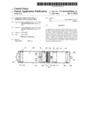
[0033] FIG. 1 is a cross sectional schematic illustration of a novel sampler designed to facilitate the capture and recovery of a representative sample of fluid from a subterranean formation for further handling and analysis.
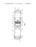
[0034] FIG. 2 is a non-limiting, exemplary cross-sectional schematic illustration of a specific component of a novel sampler. Details of a metering component and a check valve component are presented.
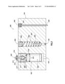
[0035] FIGS. 3A and 3B are non-limiting, exemplary cross-sectional schematic illustrations of specific components of a novel sampler.
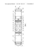
[0036] FIG. 4 is a non-limiting exemplary cross-sectional schematic illustration of a novel sampler in accordance with an exemplary embodiment of the present disclosure.
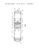
[0037] FIG. 5 is a non-limiting exemplary cross-sectional schematic illustration of a novel sampler in accordance with an exemplary embodiment of the present disclosure.
[0038] While embodiments of this disclosure have been depicted and described and are defined by reference to exemplary embodiments of the disclosure, such references do not imply a limitation on the disclosure, and no such limitation is to be inferred. The subject matter disclosed is capable of considerable modification, alteration, and equivalents in form and function, as will occur to those skilled in the pertinent art and having the benefit of this disclosure. Obvious variations on these exemplary embodiments will be readily apparent to others well versed in the art and are hereby incorporated into this disclosure by virtue of their obviousness. The depicted and described embodiments of this disclosure are examples only, and not exhaustive of the scope of the disclosure.
DETAILED DESCRIPTION OF THE INVENTION
[0039] The making and using of various embodiments of the present invention are discussed in some detail below. However, it should be appreciated that the present invention provides many applicable and synergistic innovative opportunities which can be embodied in a wide variety of specific contexts. The specific embodiments discussed herein are merely illustrative of specific ways to make and use the invention, and do not delimit the scope of the present invention. Consequently, the following embodiments are presented only to facilitate a better understanding of the proposed invention, embodiments of which might be applicable to vertical, horizontal, deviated or otherwise nonlinear wellbores in any type of subterranean formation. These embodiments may be applicable to exploratory wells, test wells, production wells, or injection wells.
[0040] Referring initially to FIG. 1, therein is depicted a novel sampler with the designation 100, operable to collect and retain a representative fluid sample from a subterranean zone of interest. The subterranean zone of interest can be considered to be a repository of some fluid type, which could be a hydrocarbon species in the form of oil or gas, or mixtures of the two, or even water, or mixtures of hydrocarbon oil, gas and water. Without in any way limiting the scope of the invention, the phases most often encountered during well testing in oil field situations could be solids of both organic and inorganic nature, an aqueous phase, hydrocarbon liquid, and hydrocarbon gas. As a rule, use is made of accessories such as tubing, piping, wireline, slickline, valves, sensors, samplers etc. to access a subterranean zone of interest so that its properties can be evaluated. Part of this evaluation step includes positioning a sampler or a plurality of samplers alongside a single or multiphase mixture that represents a reservoir fluid that is desired to be collected. When sampler and fluid to be sampled are properly positioned with reference to each other, some internal pre-set or external stimulus or signal is provided to activate the sampler and start the sampling process.
[0041] A sampler usually comprises a tubular section in which the desired sample accumulates, and additional tubular sections that help to achieve the sampler's objectives. Even though the tubular section is circular in form, there is no reason why it could not be oval, or square, or even rectangular, other than the fact that the circular tubular sections are easiest to machine, fabricate and manipulate. For convenience, and without in any way limiting the scope of this invention, the tubular section will be considered to be circular.
[0042] The first tubular section, identified as 121 is the section into which the sample of interest will flow by lateral movement of the sample piston 120 from left to the right as viewed in the plane of the page. An effective hydraulic seal is present between the piston 120 and the tubular section 121 to eliminate cross contamination of the sample being collected to the left of the piston and the working fluid to the right of it, and is achieved through the use of elastomer seals 111, a set of which are portrayed. Movement of the piston will move working fluid 130 from tubular section 121 through passage 160 and into tubular section 181.
[0043] With continued reference to FIG. 1, the front or leading piece as defined by viewing the sampler from left to right and identified in the figure as 101, acts as the required trigger which responds either to a pre-set or to some subsequent external or internal stimulus or signal so that the sample collection process can be initiated. The actual trigger can take many forms, be differently positioned, and have numerous means of activation, so that the offered generic description is merely an example of a first step needed to start the sampling process and is not meant in any way to limit the scope of this disclosure.
[0044] In a non-limiting embodiment, the trigger could be a simple on-off valve which can rotate from a closed position to an open position, thus allowing the surrounding fluid to enter the tubular section 121. In a non-limiting embodiment the rotation of the valve can be facilitated by an electric motor which gets the power to turn the valve via a self-contained battery pack together with a timer set to close a switch and deliver the electric power after some prearranged time has elapsed. Or, again without imposing any limitations, the switch to deliver the power can be activated by some external signal such as a pressure pulse, or an acoustic signal, or an electro-magnetic signal, or even an optical signal conveyed via an optical cable.
[0045] In yet another non-limiting embodiment, the trigger could be a simple mechanical, spring loaded device activated by a spring loaded clock set at the surface, such that after a set pre-arranged period of time has expired the clock returns to its start position and trips the trigger to the on position. There are any numbers of such triggers commercially available and in wide use and they will not be discussed in further detail herein. Suffice it to say that some trigger mechanism will be activated at the appropriate time to initiate the start of the sampling activity by allowing the fluid surrounding the sampler to enter the sampler.
[0046] Once the trigger has been activated, the fluid to be sampled can now freely enter the openings in the sampler identified as 110 and start filling the sampler. These openings can also take many forms and be variously located without in any way limiting the scope of this disclosure. For example, even though the openings are portrayed along the circumference of tubular element 121, the opening could as easily be singular and in front of the sampler indicated by the trigger component 101. Suffice it to say that there is either a singular or multiple set of openings in the sampler, usually at the leading edge, which connect via some passage to a point just in front of the sample collecting piston identified as 120, such that when the sampler is triggered to start collecting a sample, the fluid to be sampled and which is usually surrounding or in communication with the sampler, is brought in contact with the space in front of piston 120, i.e. between the sample piston 120 and the sampler openings 110 so that sample collection can commence.
[0047] The element identified as 140 is a distinct spacer that provides demarcation between the tubular sections 121 and 181 while also containing other functional elements as discussed in some detail below, all of which are needed to deliver the proper and complete sampling function. The end piece marked as 191 is usually some generic connector that allows the sampler to either be attached to some other sampler as in a sequence of samplers, or to a larger carrier that is carrying a number of samplers, or to some other means of conveyance of the sampler, either slickline, wireline, coiled tubing, or electrically powered tractor motor, needed to convey the sampler to the subterranean location.
[0048] As the fluid to be sampled enters the sampler it first encounters the sample piston identified as 120. In order to minimize the possibility for flashing the sample and making it go two or more phases, the sample piston 120 is backed up by the working fluid 130. The working fluid 130 can be any convenient fluid whose restricted movement through a metering section, shown as 160, slows the movement of the sample piston and does not allow the sample to flash. In this instance it is significant that the working fluid is also a dielectric fluid, in the sense that it will only poorly conduct electricity.
[0049] Another advantage of immersing all the components in a dielectric working fluid would be the heat sink such a fluid would represent. Essentially, because of the high temperature environment the motor and electronics will be exposed to, in addition to the heat the motor and electronics will generate when called upon to perform their functions, it might be advantageous to improve the heat transfer characteristics of the environment surrounding the motor. This can be most conveniently achieved by immersing the motor and its ancillary electronics in a medium that is electronically non-conducting, most conveniently a dielectric fluid. Because the surrounding fluid is electrically non-conducting, the working of the motor will in no way be affected. This is a relatively routine practice for downhole tools and will not be discussed in greater detail here. Suffice it to say that the performance and longevity of the motor and the accompanying battery can be considerably enhanced by improving their ability to dissipate heat, a step most easily accomplished by immersing the motor, battery and associated electronics in a dielectric fluid. A typical non-limiting example of such a working dielectric fluid would be say the Paratherm NF heat transfer fluid available from the Paratherm Corporation.
[0050] The metering section is invariably a choke or some similar restriction that limits the rate at which the working fluid can move through it. Without in any way limiting the scope of the invention, the metering section as discussed in this particular embodiment could be best represented by a Lee Visco Jet type device as available through the Lee company, Connecticut, USA. The Lee Visco Jet device is commercially available and descriptions of the detailed workings are present in the open literature, for which reason it will not be discussed in great detail herein. Let it suffice that a mechanism for restricting the flow of the working fluid 130 between the tubular sections 121 and 181 is available such that the controlled collection of a sample representative of the fluid surrounding the sample entry point 110 is feasible.
[0051] The metering section 160 is firmly encased and hydraulically sealed in the fixed element 140, usually in advance of or in association with a passage shown as the tubular element marked 145. The passage marked as 145 serves to provide an outlet for the working fluid 130 to transit from the left side of fixed element 141 to the right side in a slow and controlled fashion as the working fluid transits through the metering section. A non-limiting embodiment of this metering device and passage 145 are presented in greater detail in FIG. 2.
[0052] Adjoining the metering section 160 is a check-valve component marked as 161 which serves to provide a unidirectional restriction to the flow of working fluid. For the purpose of this embodiment the unidirectional flow would be from tubular 181 to tubular 121. Flow in the opposite direction, namely from tubular 121 to tubular 181 would be restricted by the check valve's action. Associated with the check-valve component 161 is a tubular element marked 146 so positioned as to allow movement of pressurized working fluid from the discharge of pump 150 through element 146 and into the tubular section 121 and subsequently into the space to the right of piston 120. A non-limiting embodiment of this unidirectional check-valve device and accompanying passage 146 are also presented in greater detail in FIG. 2.
[0053] FIG. 2 presents the metering section 160 in greater detail. A principal element of the metering section is the Lee Visco Jet unit as discussed above, and identified as component 202 for controlling the rate of flow of working fluid from tubular section 121 through passage 145 and into tubular section 181. The Lee Visco Jet unit 202 makes a hydraulic seal with the opening 160 by means of the elastomer seal shown as 201. Consequently, all fluid entering section 160 during the sampling step is forced to go through the metering section. However, once the required sample has been collected, the passage through the metering section needs to be closed to curtail further loss of pressurized working fluid through the metering section.
[0054] This closure is accomplished by the action of the check dart 205 going on-seat on the sealing surface 215 when closure is required. The seat 215 is hydraulically sealed against the top face of the Visco Jet via the circular elastomer seal 216 so as to ensure that flow of working fluid is compelled to be past the face of the dart 205 and through the Visco Jet. The seat 215 is held firmly in place by the locking nut 217 which screws into the top face of component 160 to hold the entire assembly together, while also activating the seal 216.
[0055] The locking nut 217 contains the openings 219, two shown, for accommodating the shear pins 210, again two shown. During assembly the shear pins are inserted through the openings in the locking nut and penetrate through to the radial groove 220 cut into the elongated cylindrical section of the sealing dart. As can be seen in FIG. 2, the pins serve to hold the dart suspended above the sealing face of the seat 215 allowing working fluid to flow past the dart and into the metering section.
[0056] However, once the sample collection step is concluded, the face of piston 120 adjoining the side containing the working fluid will be abutted against the face of element 140 containing the metering component 160. In this configuration the face of piston 120 will exert the necessary force against the dart 205 to cause the shear pins to shear, thus releasing the dart from its confinement in the open position. The force of the pressurized working fluid pushing against the released dart in conjunction with the spring 211 will now cause the dart to go on seat, essentially shutting of this flow path for the working fluid. As long as the pressure of the working fluid in the tubular section 121 exceeds the pressure of the working fluid in the tubular 181, the dart will stay on seat and close out that passage.
[0057] The component 161, comprises primarily a check dart 265, and serves the opposite function. The check dart 265 is spring loaded via spring 262, while the spring is held in place via the nut 263 which threads into the body of piece 140. The nut 263 has a passage 264 through it to allow easy flow of working fluid in either direction through it. The spring loaded check dart stays on seat during the entire sample collection step so that movement of working fluid from tubular section 121 to 181 can only take place through the metering section 160. However, once the sample collection step is concluded, and the pump 150 is activated to start pressurizing the working fluid behind piston 120, the high pressure discharge of the pump entering the component 161 via the tubular passageway 146 will force the dart 265 off-seat and allow pressurized working fluid to enter the space behind the piston 120.
[0058] Also shown in FIG. 2 is the pressure monitoring device marked 240. Even though such devices are quite common in the industry and will not be specifically discussed in great detail here, the output of such a pressure monitoring device plays a significant role in the proper operation of the sampler. In one non-limiting embodiment, the pressure measuring device serves to measure and convey the pressure of the working fluid to the electronic controller associated with the motor, which in turn will control the movement of the electric motor and the pump such that some pre-set value of pressure is maintained during the entire sampling and recovery cycle. Because the working fluid is in hydraulic communication with the collected sample, the pressure measured at 240 is also the pressure of the collected sample.
[0059] In a non-limiting embodiment, the output of the pressure monitoring device is shown exiting in the form of two or more leads marked as 230 in FIG. 2. This output is inputted into the electronic controller that serves to define the action of the pump 150. Without in any way limiting the scope of the invention, consider the case where a sample has been collected at a reservoir pressure of 6000 psi. In keeping with the requirements of single phase sampling, it would be required that the sample pressure be maintained at least at 6000 psi, and preferably a higher pressure at least 2000 psi above the reservoir pressure, namely 8000 psi during the sample recovery step. By constantly monitoring the pressure and transmitting the reading to the electronic controller, the electronic controller will in turn activate the pump to deliver the required pressure and keep the sample single phase.
[0060] The choice of pressure at which the sample is maintained as single phase is case specific, but as a rule should always be at least 2000 psi above the pressure at which the sample is collected. Consequently, if a prior knowledge of the reservoir pressure is available, the electronic controlling unit can be pre-programmed to keep the collected sample at some pressure that is at least 2000 psi above this value. On the other hand, the electronic controller can be set to always keep the pressure at least 2000 psi or higher than the registered sample pressure recorded during or at the end of the sampling step. This remarkable flexibility for pressure maintenance is unique to this design and is another significant distinguishing feature that demarcates this design from those that have preceded it.
[0061] The pressure transducer needed for this application is quite commonplace in the industry, with any number of variations fit for purpose readily available, so that a lack of elaboration of its exact features and mechanism does not in any way detract from the scope of this invention. As presented in the non-specific embodiment of FIG. 2, the pressure information measured by the pressure transducer 240 is conveyed to the electrical programmable control unit directly by means of the electrical cable identified as 230. However, this should in no way be considered limiting, as some other means including but not limited to acoustic or electro-magnetic means, including a radio or optical signal will be equally effective in conveying the necessary pressure information to the electronic controller.
[0062] Returning again to FIG. 1, element 150 is a high pressure hydraulic pump with a set of inlets shown as 151 and an outlet for the high pressure discharge which is also an extension of the tubular element 146. This is a simple hydraulic pump, and a number of commercial manufacturers can be approached to deliver a desirable pump for such an application. It is recognized that a pump specific to such an application will need to be custom designed and manufactured, but this is a relatively routine practice in the industry. A typical example of a pump applicable for such purpose would be a micro-hydraulic pump available from say, and presented only as a non-limiting example of a potential source, the company Petroleum Accessories, Inc., which can be approached to deliver a micro-hydraulic pump custom designed for this purpose.
[0063] The power required to run the pump 150 comes from the electrical motor marked 153, the drive shaft of which is connected to the drive shaft of the pump 150 via the coupling marked as 152. An electric motor is preferable because they are capable of quickly generating significant amounts of torque which would be needed to work the hydraulic pump 150 to generate the significant overpressure that will be required for single phase sampling. As presented in FIG. 1, the main shaft of the electric motor is directly connected at 152 to the drive shaft of the pump, but this need not be the case. Component 153 could be a combination of electric motor and gear box such that the torque delivered by the drive shaft of the motor can be greatly increased through the working of the gearbox using appropriate gear ratios to deliver the required torque needed to drive the hydraulic pump against significant sample pressure.
[0064] The electric motor console identified as 153 can also contain the electronic controller, not shown separately, that will control the actions of the electric motor. Thus for example, and without in any way limiting the scope of the invention, certain functionalities can be programmed into the electronic controller at the surface, or conveyed by some additional means from the surface to the electronic controller at the appropriate time to appropriately influence the workings of the motor. In one non-limiting embodiment, the electric motor and adjoining pump will stay quiescent until the sample collection step has concluded, at which point the electrical motor and pump will be activated to pressure up the working fluid surrounding them and discharge this pressurized fluid through passage 146 into the space to the right of piston 120, thus exerting pressure on the collected sample to counter the pressure drop due to sample shrinkage. As indicated above, the output of the pressure monitoring device 240 can also be used to activate the motor and pump.
[0065] In a slickline application, power for the electric motor will come from the power pack depicted in FIG. 1 by the number 160 and transmitted to the electrical motor via the electrical umbilical 154. The power pack in this instance could be a battery pack, rechargeable or otherwise, with the capacity to provide the needed electrical energy for the motor to perform its duty over the short number of hours or even days required for a typical slickline sampling operation. In a wireline or e-line application the power pack may be dispensed with altogether and the necessary power provided by a surface source to the motor via the appropriate electrical conduit. The same electrical conduit can also be used to transmit the necessary instructions required by the electric motor to perform its sampling function. Understandably, in some applications it might be appropriate to have a combination of external power source and internal battery pack.
[0066] In a carrier based application, where a number of such samplers are simultaneously conveyed to location on pipe or tubing, the power pack could be a much larger separate element carried as part of the carrier itself and used to provide power to a number of samplers. Clearly, and without in any way limiting the scope of this invention, the required power source can take numerous forms depending on the specific conveyance mechanism utilized for transporting the sampler to the vicinity of the desired subterranean zone to be sampled.
[0067] In slickline or carrier based operations where a battery pack is required to deliver the necessary electrical power, the battery pack can take on any of a number of configurations. In one non-limiting embodiment the power source could be what are routinely referred to as primary or non-rechargeable cells, a typical non-limiting example of which would be a routine alkaline battery, but could include a host of variations such as a lithium air battery, mercury battery, molten salt battery, zinc based battery, etc.
[0068] In yet another non-limiting embodiment, the power source could be what are routinely referred to as secondary cells or rechargeable batteries, a typical non-limiting example of which would be lead-acid batteries, Lithium based batteries including Lithium-polymer batteries, nickel based batteries including nickel metal hydride, sodium based batteries, rechargeable alkaline batteries, zinc batteries, etc.
[0069] The end piece of the sampler designated by 191 is just an ordinary mechanical connector for attaching a sampler to an adjoining sampler or to any appropriate conveyance mechanism such as slickline, wireline, coiled tubing, pipe, tubing, etc.
[0070] The lateral movement of the piston 120 from left to right during the sample collection process will eventually bring the piston in close proximity or direct contact with the fixed element 140. At this point no additional sample can be collected and the sampler's function needs to revert to a mode appropriate to the sample's satisfactory recovery to the surface. Without in any way limiting the scope of this invention, this can be most simply accomplished by a simple on/off switch located on the face of element 140 that would abut piston 120 when it reaches the end of its stroke. Closing off the switch would serve to activate an electronic programmer, not shown for the sake of simplicity, that would initiate the function of the electric motor and hence the pump, to keep the sample single phase during recovery to the surface. It should be readily apparent that neither the action of the switch nor the shearing of the pins 210 can interfere with the performance of each other's function. Thus dimensionally the length of the dart 205 and the vertical position of the above mentioned switch would be such that the pins 210 will shear, following which the switch will activate.
[0071] The controlled movement of piston 120 from left to right during the sample collection step due to the slow movement of working fluid out of tubular section 121 and through the metering section 160 will result in working fluid entering the tubular section 180 through the passageway 145. The pump 150, the motor 153, and the battery pack 160 all have adequately sized passages, shown as 141, between their outside diameters and the inside diameter of tubular 181 such that the working fluid entering at 145 can have access to the complete tubular section 181. In a non-limiting embodiment, an example of this passage marked 141 is shown in FIGS. 3A and 3B for the pump 150 and the motor 153. One well versed in the art would have no trouble recognizing that a similar passageway would also be available for the movement of the working fluid past the battery pack marked 160. As long as the working fluid is a non-conducting medium there is no issue with completely immersing pump, motor, and battery pack in the working fluid.
[0072] Prior to commencement of sampling, the piston marked as 185 in FIG. 1 will start adjacent to and abutting the battery pack 160. When sampling commences, working fluid will enter tubular section 180 and start to fill the dead volume surrounding and adjoining 150, 153, and 160. Once the dead volume is filled, continued entry of the working fluid will cause the piston 185 to move laterally from left to right to encompass a larger volume shown as 170. The volume to the right of the piston 185 is initially charged with some inert gas like nitrogen at some reasonable pressure in the range of 100 to 300 psi. Neither the stated nature of the gas nor the initial charge pressure should be viewed as limiting and are meant only to exemplify one embodiment of this invention. Any other inert gas, for example helium, would work equally well in this application.
[0073] The stated initial charge pressure of the gas can also cover a broad range as dictated by the actual circumstance under which the sampler is to be used. Any judicious initial charge pressure such that when both pistons 120 and 185 are bottomed out, namely have moved as far right as they will go, results in the final pressure at 182 being significantly less than the pressure of the reservoir fluid entering at 110, will be adequate.
[0074] The purpose of the nitrogen charge is primarily to exert lateral pressure on piston 185 from right to left such that the tubular section 181 to the left of piston 185 is always liquid full irrespective of the angle or configuration of the sampler. Essentially, by virtue of the gas pressure at 182 exerting a lateral force from right to left on piston 185, the internal volume of the tubular section 181 to the left of piston 185 will always be liquid full irrespective of its configuration, and consequently the pump 150, with its fluid inlets marked as 151, will always have a full head and be primed for action.
[0075] As discussed in a previous embodiment, the hydraulic pump does not activate until the entire sample has collected in the sampling space, following which, the hydraulic pump acts as a pressure maintenance device to assure single phase sampling. In yet another non-limiting embodiment it is feasible to activate the pump during the sample collection step itself to improve the quality of the collected sample. Thus, for example, even as the sample is being collected and the sample piston is moving in discrete increments to displace the working fluid from space 121 to space 181, the pump, through the agency of the electrical motor, working under the instructions of the electronic controller, can be activated to inject working fluid at high pressure from the low pressure side to the high pressure side. In this mode the sample will be repeatedly over-pressured even as it is being collected to ensure that the sample stays single phase during the collection step to deliver a better quality sample. Understandably, when the pump stops, the metering action will once again dominate, and sample collection will resume as the working fluid moves through the metering section. Such a unique flexibility in motion is not available with any other sample collecting tool and makes this design invaluable for a range of applications including heavy oils at one extreme and wet condensates at the other.
[0076] Another non-limiting embodiment of this concept is presented in FIG. 4, wherein the flexibility of the design is considerable enhanced by inclusion of a solenoid control valve, marked as 420, in conjunction with the hydraulic pump 450. The incorporation of the solenoid control valve allows considerably greater flexibility in how the input and output to and from the hydraulic pump will be directed. In this embodiment the electric motor will still drive the hydraulic pump which will have a fixed low pressure inlet marked as 418 and a high pressure discharge marked as 432.
[0077] Positioned between the hydraulic pump and the fixed member 140 will be the solenoid control valve 420 activated by a separate power source 421 and controlled by the electronic controller. The solenoid valve assembly will have a plurality of openings, with 4 shown and marked as 408, 412, 416, and 430 for the purpose of this discussion. Internal to the solenoid valve will be a number of passages and associated pistons, check valves, rotary components, and seals for controlling the flow of fluids between the various openings. Such solenoid control valves are quite common in industrial use and will not be elaborated on further here. Suffice it to say that the action of the solenoid valve will be sufficient to achieve the desired communication between the various openings as appropriate to the performance of the sampler's function.
[0078] In actual practice, at the start of a sampling operation the internal configuration of the sampler will be similar to that shown in FIG. 4, with the sample collecting piston 120 at the top of its stroke, to the far left in a non-limiting configuration as shown in FIG. 4, and positioned to start collecting a sample. As indicated above, for the sampling step to start some external or predetermined signal will open a passage between the space where a sample is to collect to the left of the sampling piston 120, and the fluid to be sampled present in the space surrounding the sampler. Even though that passage has been opened, sampling cannot commence unless the working fluid in space 130 positioned behind and to the right of the sampling piston is displaced, thus allowing the sampling piston 120 to move from left to right as presented in FIG. 4, thus allowing a volume to open to the left of the sampling piston into which a sample can collect.
[0079] At the start the solenoid valve will be positioned such that working fluid in space 130 will enter passage 460 to flow through passage 410 and enter the solenoid valve opening 408 from where it will be redirected to opening 430 and thence through passage 432 which is the intake to the hydraulic pump 450. In turn the hydraulic pump will pressure up the working fluid and discharge it through the discharge port 418 to the solenoid valve opening 416, through the valve and out opening 412 and passage 414 into via the passages 141 and into the space 170 where the bulk of the low pressure working fluid resides. This process can be continuous in transiting the working fluid from space 130 to space 170 until the entire sample collection step has been completed.
[0080] Once sample collection is complete using any of the criteria described in greater detail above, sample recovery in a representative condition can be initiated. For the sample to be considered representative, the sample pressure must be maintained at least, and preferably much higher than the pressure at which the sample was collected. This requirement is most easily met in this particular embodiment by activating the solenoid valve to appropriately reconfigure its internal passageways. Essentially, by adjusting the internal settings of the solenoid valve, the inlet to the pump 432 is now in communication with the port 414, while the high pressure outlet of the pump 416, now communicates via 410 to the space 130 where the high pressure working fluid pressurized by the pump serves to maintain the sample in a representative state.
[0081] It should as well be obvious that this approach also provides a means for recovering a more representative sample during the actual sampling step. Thus, during the actual collection step it is feasible to first set the solenoid valve in such a configuration that sample will enter the sampling space in front of the sampling piston. However, after a small volume of sample has been collected, say 5 to 20 cc, the solenoid valve can be switched so that the pump pushes pressurized working fluid back into space 130, thus increasing the pressure of the working fluid on the high pressure side to above the reservoir pressure, driving the collected sample back into a single phase condition. By once again reversing the solenoid valve, additional sample can be collected and then re-pressurized. This cycle of incremental sample collection and re-pressurization can be repeated a number of times until the desired total volume of representative sample is collected. This is a significant distinguishing feature of this design as no other existing design for sample collection can deliver such a representative sample.
[0082] The principal advantage of such an embodiment is the considerably improved simplicity of the overall design, because the need for a complex metering section presented as item 160 in FIG. 2 as also in all likelihood the need for the unidirectional check-valve 161 also presented in FIG. 2 can be eliminated. As shown in FIG. 4, the movement of working fluid between the high pressure side 130 and the low pressure side 170 will be controlled by the setting and the internal check valves associated with the solenoid valve.
[0083] The hydraulic pump exploited in the aforementioned embodiments is a relatively simple and conventional hydraulic pump with no exceptional capabilities. However, another non-limiting embodiment is presented in FIG. 5 which exploits a more complex pump design. This embodiment exploits a double acting hydraulic function available in certain unique pump designs. Essentially, most simple hydraulic pumps have a specific and non-interchangeable intake and outlet port as shown in FIGS. 1 and 4, such that irrespective of the direction of rotation of the motor, the intake and outlet ports remain fixed in their function. However, certain unique hydraulic pumps are available whereby simply reversing the direction of rotation of the motor allows a reversal of the function of the two ports.
[0084] Turning to FIG. 5, consider for example the case where such a pump has an inlet port marked as an example only as 551, and a corresponding outlet port marked as 546, as shown in FIG. 5. Consider further the situation where such a sampler has been positioned at a location appropriate for collecting a sample. As discussed previously, before a sample can be collected, working fluid, which is being held in place by the dual acting check valves built into the body of the hydraulic pump, must be moved from the high pressure space 130 to the low pressure space 170. If the electric motor were to be now rotated, and as an example only, in say the clockwise direction, then, provided the internal configuration of pump and valves is appropriate, the port 546 connected to the opening 560 will act as the inlet to the hydraulic pump, with the ports identified as 551 serving to discharge working fluid as it goes through the pump into the low pressure side 170 of the working fluid space. This process can be continuous in transiting the working fluid from space 130 to space 170 until the entire sample collection step has been completed.
[0085] Once sample collection is complete using any of the criteria described in greater detail above, sample recovery in a representative condition can be initiated. For the sample to be considered representative, the sample pressure must be maintained at least, and preferably much higher than the pressure at which the sample was collected. This requirement is most easily met in this particular embodiment by reversing the direction of the motor's rotation. When the motor's rotation is reversed, the controlled movement of a double acting hydraulic cylinder in conjunction with the dual action check valves will act to reverse the action of the pump. Essentially, by the simple expediency of reversing the motor's direction of rotation, the ports identified by the number 551 in FIG. 5 now become the inputs to the pump, while the port 546 becomes the high pressure discharge port. It should be obvious that in this configuration the pump can be used to move the working fluid from the low pressure side denoted by 170 in FIG. 5 to the high pressure side 130, and at sufficient pressure to maintain the sample in a representative state during recovery.
[0086] It should as well be obvious that this approach also provides a means for recovering a more representative sample during the actual sampling step. Thus, during the actual collection step it is feasible to first turn the motor in such a direction that sample will enter the sampling space in front of the sampling piston. However, after a small volume of sample has been collected, say 5 to 20 cc, the direction of the pump can be reversed so that the pressure of the working fluid on the high pressure side increases above the reservoir pressure, driving the collected sample back into a single phase condition. By once again reversing the motor's direction, additional sample can be collected and then again re-pressurized. This cycle of incremental sample collection and re-pressurization can be repeated a number of times until the desired total volume of representative sample is collected.
[0087] In order to maximize the opportunities for such a sampling device across the full range of potential reservoirs it might encounter, it is expected that it will have a pressure rating of up to say 40,000 psi, though more likely this pressure rating will be in the 20,000 psi range. This pressure rating implies that the sampler can be immersed in an environment where the surrounding fluids are at a pressure of up to 20,000 psi or 40,000 psi without the sampler suffering any mechanical failure.
[0088] The physical dimensions of the sampler may vary significantly depending on the particular application, especially as dictated by the means of conveyance to a reservoir of interest. In those instances where a carrier is in use for conveying the samplers, the diameter of the sampler might vary anywhere from one inch to as much as three inches or more. However, for slickline or wireline applications the dimensions of the surface lubricator which is to be used to introduce the sampler into the well bore, as also the internal diameter of the elements of the tool string the sampler will need to traverse, tends to be the limiting factor. In such cases the diameter will tend to be more in the range of 2 inches with an overall length of 17 feet. However, it needs to be kept in mind that these dimensions are merely suggestions dictated by specific operations and could vary significantly as the opportunity and the means for conveyance change.
[0089] The power required to run the motor, the electronics, and the ancillary kit associated with the sampling step will also be a significant consideration in the dimensions and performance of the sampler. Thus, in a slickline application the power will need to be provided by battery cells appropriately designed and sized for this application. However, these battery components are commercially readily available and do not need to be elaborated on here. In a wireline or e-line application all the power needed for the operation of the sampler will be delivered by the electrical cable itself, resulting in a much simpler and shorter sampler with an extended functional life downhole. In carrier based operations, the battery pack could be incorporated with the sampler itself or could be a larger and separate battery pack designed to accommodate a larger number of samplers for extended working life downhole.
[0090] It should be obvious to one skilled in the art and enlightened by the teachings of this disclosure that the sample size collected can be varied significantly and be influenced by the needs of a particular application or situation. The unique features of the disclosed design attending the present invention results in the elimination of a significant amount of overall sampler volume and length in comparison to the prior art. This eliminated volume and length can be exploited in the present design to deliver a much larger volume of captured sample. However, in the cause of flexibility and redundancy it might prove advantageous to collect multiple samples rather than a single large sample. This is facilitated in the present design such that two or even three separate and distinct samplers might be run in the same overall dimensions as would deliver only a single sample volume in the more traditional designs covered by the prior art. Accordingly, the sample volume can range anywhere from 5 cc to in excess of 10,000 cc depending on a particular application, without departing from the spirit of this invention.
[0091] While this invention has been described with reference to numerous embodiments, this description is not intended to be construed in a limiting sense. Instead it is expected that the discussed embodiments would serve to demonstrate the versatile ability of the proposed sampler design to accommodate the capture and representative preservation of single and complex multiphase streams of variable ratios and flow rates of the various components that can be encountered during a well test operation. Understandably, various modifications and combinations of the illustrative embodiments as well as other embodiments of the invention will be apparent to persons skilled in the art upon reference to the description. It is, therefore, intended that the appended claims encompass any such modifications or embodiments.
User Contributions:
Comment about this patent or add new information about this topic:
| People who visited this patent also read: | |
| Patent application number | Title |
|---|---|
| 20140182771 | SONICATION FOR IMPROVED PARTICLE SIZE DISTRIBUTION OF CORE-SHELL PARTICLES |
| 20140182770 | TACTILE RELIEF FILMS, DECALS AND STICKERS FOR INDICATING OBJECT CHARACTERISTICS |
| 20140182769 | Ultrasonic Press Using Servo Motor With Delayed Motion |
| 20140182768 | IN-LINE GIFT CARD PERSONALIZATION AND PACKAGING PROCESS |
| 20140182767 | METHOD OF PRODUCING CLEANING MEMBER |
Images included with this patent application:
 |  |
 |  |
 |  |
| Similar patent applications: | |
| Date | Title |
|---|---|
| 2014-01-30 | Apparatus and method for representative fluid sampling |
| 2013-06-20 | Wear sensor for a pipe guide |
| 2010-02-25 | Method and apparatus for obtaining fluid samples |
| 2013-01-24 | Apparatus and method for improved fluid sampling |
| 2014-04-17 | Method for launching replacement balls |
| New patent applications in this class: | |
| Date | Title |
|---|---|
| 2016-12-29 | Fluid extraction system having power control sub-system and related methods |
| 2016-05-19 | Metal bellows with guide rings |
| 2016-05-12 | Electric submersible pump inverted shroud assembly |
| 2016-02-18 | Systems and methods for variable speed drives |
| 2016-02-18 | Armored power cable installed in coiled tubing while forming |
| New patent applications from these inventors: | |
| Date | Title |
|---|---|
| 2017-02-16 | Mixing fluids with weighted aqueous phases |
| 2014-11-27 | Apparatus and method for representative fluid sampling |
| 2014-01-23 | Method and apparatus for analyzing multiphase fluid flow using a multivariate optical element calculation device |
| 2013-08-01 | Reconstructing dead oil |
| Top Inventors for class "Wells" | |
| Rank | Inventor's name |
|---|---|
| 1 | Michael L. Fripp |
| 2 | Jean Marc Lopez |
| 3 | Michael H. Johnson |
| 4 | Jørgen Hallundbaek |
| 5 | Dennis P. Nguyen |