Patent application title: Hands-Free Multi-Use Long Gun Carry Pack & Related Methods
Inventors:
Tracey Ponder (Dayton, TX, US)
IPC8 Class: AF41C3300FI
USPC Class:
224149
Class name: Package and article carriers carried by animate bearer receiver holding butt end of rifle or shotgun stock
Publication date: 2014-06-05
Patent application number: 20140151413
Abstract:
In general, disclosed is a multi-use and gun-protective apparatus for
secure and hands-free carrying of a long gun in close proximity (in time,
distance, and procedure) to a gunman carrier's gun firing position.
Basically, in one embodiment, the apparatus is a reversible, open-ended,
and chest-mounted bi-fold pouch configured to fold around at least part
of the receiver portions (the portions of the rifle that contains the
operating parts, e.g., bolt carrying group, trigger group, or magazine
port) of a long gun). In operation, a long gun may be provided to the
pouch so that the gun is transversely oriented with respect to torso of
the gun carrier whereby the barrel of the long gun extends out of one end
of the pouch while the stock of the long gun extends out of the other end
of the pouch. When gun firing or deployment is necessary, the gun is
located on the chest of carrier so that the barrel or stock of the gun
may be gripped while the pouch is concurrently unfolded to result in the
carried gun falling from the pouch into the carrier's gun firing
position.Claims:
1. A gun carrying and deployment apparatus comprising: a bi-fold pouch
operably configured to be positioned on a torso of a gunperson, said
bi-fold pouch featuring at least one fastener on a non-folded side of
said pouch and whereupon said at least one fastener may be rapidly
unfastened to allow deployment of a firearm.
2. The gun carrying and deployment apparatus of claim 1 further comprising an aperture disposed along the fold of said bi-fold pouch and operably configured to accommodate the receiver of a firearm.
3. The gun carrying and deployment apparatus of claim 1 further comprising a plurality of fasteners which may be unfastened to allow rapid deployment of a firearm.
4. The gun carrying and deployment apparatus of claim 1 further comprising snap loops for securing said bi-fold gun carrying and deployment apparatus to a vest.
5. The gun carrying and deployment apparatus of claim 4 wherein said vest is a MOLLE vest.
6. The gun carrying and deployment apparatus of claim 4 wherein said vest further defines a gun accessory pocket.
7. The gun carrying and deployment apparatus of claim 1 wherein said bi-fold pouch is segmented to accommodate a high-capacity magazine for a rifle.
8. The gun carrying and deployment apparatus of claim 1 wherein said bi-fold pouch is unfolded rapidly by use of a rip cord.
9. The gun carrying and deployment apparatus of claim 1 wherein said bi-fold pouch is unfolded and operationally configured to carry guns from any of the group of firearms consisting essentially of either shotguns, rifles, assault rifles or machine guns.
10. The gun carrying and deployment apparatus of claim 1 wherein said bi-fold pouch may be transversely or diagonally slung across the torso of the user.
11. A method of securing and deploying a gun comprising the steps of: placing a bi-fold pouch on a torso of a gunperson, wherein said pouch is folded around a portion of the gun and wherein said gun rests in the fold of said pouch; unfolding the pouch, whereupon said gun is rapidly released from said pouch and available for firing.
12. The method of claim 11 further comprising the step of securing said bi-fold pouch on the torso of a gunman by fastening means connected to a vest.
13. The method of claim 12 wherein said fastening means are snap loops.
14. The method of claim 11 wherein the step of unfolding said pouch is accomplished rapidly via the release of fasteners connected to the exterior portion of said bi-fold pouch.
15. The method of claim 11 wherein the gun secured by the pouch is from any of the group of firearms consisting essentially of any of either rifles, shotguns or assault rifles.
16. The method of claim 11 wherein the bi-fold, pouch is rapidly unfolded by pulling a rip cord that allows said gun to be freed of the pouch and quickly fall into the hands of the user where it may be quickly positioned for firing.
17. The method of claim 11 wherein said releasably secured in a carrying position by a plurality of fasteners.
18. A gun carrying apparatus comprising: a bi-fold pouch featuring a forward flap and a rear flap separated by a fold said forward and rear flaps being substantially rectangular and being configured to envelop a portion of a firearm; wherein said flaps may be releasably secured to one another at their non-folded sides; said non-folded sides being releasably connected to one another by demonstrating is a is a fast as he is in a fastening means.
19. The gun carrying apparatus of claim 18 further comprising an aperture along said fold of said pouch, whereby the of a firearm may be accommodated. The gun carrying apparatus of claim 18 wherein said flaps are releasably secured to one another by buckle fasteners that connect to snap loops for connection to a vest.
Description:
CROSS-REFERENCE TO RELATED APPLICATIONS
[0001] This application claims the benefit and priority of U.S. Prov. Pat. App. Ser. No. 61/565,731 (filed Dec. 1, 2011) entitled "Multi-use long gun carry pack."
STATEMENT REGARDING FEDERALLY SPONSORED RESEARCH OR DEVELOPMENT
[0002] Not applicable.
BACKGROUND OF THE INVENTION
[0003] 1. Field of Invention
[0004] This specification discloses subject matter in the field of hands-free and multiple use carrying packs for long-guns. In particular, the disclosed subject matter is in the field of hands-free apparatus for releasably securing a long gun to a person.
[0005] 2. Background of the Invention
[0006] Long guns are an elongated class of firearms generally designed to be discharged by a gunman with an outstretched arm supporting the barrel of the gun while the gun stock is braced against his or her shoulder. Long guns have many practical uses, particularly in military and sportsman arts. Despite this utility, long guns are usually heavy and lengthy whereby manually carrying such guns can be difficult and tiring. Furthermore, manually carrying a gun occupies the gunman's hands and arms so that multi-tasking by the carrier is limited.
[0007] Many apparatus exist which allow hands-free carrying of a long gun on the back of a gunman. While loading a long gun on the back of the gunman eases the gunman's burdens of manually carrying the gun, apparatus for back mounting long guns are not entirely suitable for all situations because, the gun is hard to reach and far (in time, distance, and procedure) from a gunman's fire-ready position.
[0008] Other apparatus for assisting a gunman's carrying of a long gun also exist, but such apparatus are either uncomfortable for the gunman or expose the gun and its components (e.g., sighting elements) to damage. For example, sling type apparatus exists for supporting a long gun over a shoulder of the gunman, but such apparatus: focus the weight of the long gun on a single extremity (e.g. a single arm or shoulder) so that carrying the gun becomes uncomfortable; leave the gun dangling on the shoulder so that the gun may either be dropped or hit against items; and place the gun at a location that is far (in time, distance, and procedure) from the gunman's fire-ready position.
[0009] In view of the foregoing, there is a need for gun-protective multi-use apparatus for secure and hands-free carrying of a long gun in close proximity (in time, distance, and procedure) to a firing position of a gunman carrier.
SUMMARY OF THE INVENTION
[0010] In view of the foregoing, it is an object of the present specification to describe a multi-use and gun-protective apparatus for secure and hands-free carrying of a long gun in close proximity (in time, distance, and procedure) to a gunman carrier's gun firing position. In one embodiment, the apparatus is a reversible, open-ended, and chest-mounted bi-fold pouch for securely carrying of a gun in a transverse orientation (whether perpendicular or oblique) with respect to the carrier's torso. Suitably, the apparatus may be reversible in that the gun may be oriented with its barrel or stock on either side of the carrier to accommodate left or right handed gunmen. Suitably, the pouch may be provided to a vest, halter, or any other outfit for the torso of a person. In another embodiment, such outfits may be provided with one or more pockets for carrying gun accessories. Other objectives will be readily apparent to those of skill in the art after reading this disclosure.
BRIEF DESCRIPTION OF THE FIGURES
[0011] The manner in which these objectives and other desirable characteristics can be obtained is explained in the following description and attached figures in which:
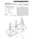
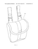
[0012] FIG. 1 is a front view of a closed embodiment of a multi-use and gun-protective apparatus 1000 for secure and hands-free carrying of a long gun in close proximity (in time, distance, and procedure) to a gunman carrier's gun firing position;
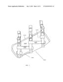
[0013] FIG. 2 is a front view of an open embodiment of the apparatus of FIG. 1;
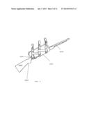
[0014] FIG. 3 is a front view of the apparatus 1000 of FIGS. 1 and 2 with a long-gun 5000 provided thereto;
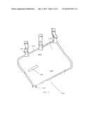
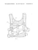
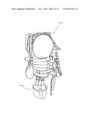
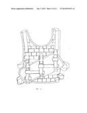
[0015] FIG. 4 is a front view of a MOLLE vest 2000 with the apparatus 1000 attached thereto;
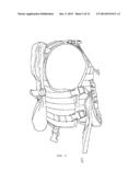
[0016] FIG. 5 is a right side view of the vest 2000 of FIG. 5;
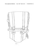
[0017] FIG. 6 is a back view of the vest 2000 of FIGS. 5 and 6;
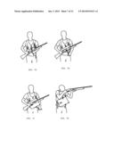
[0018] FIGS. 7A through 7D illustrate a preferred mode of operation for the disclosed apparatus 1000;
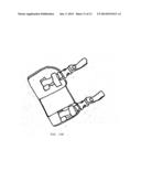
[0019] FIG. 8 is a perspective view of a basic embodiment of a pocket 3000 for carrying gun accessories;
[0020] FIG. 9 is a side view of the vest 2000 with the pocket 3000 of FIG. 8 attached thereto;
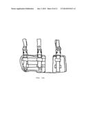
[0021] FIGS. 10A and 10B show alternative embodiments of the apparatus 1000; and,
[0022] FIG. 11 is a front view of an alternate embodiment of a vest 2000.
[0023] It is to be noted, however, that the appended figures illustrate only typical embodiments of the disclosed apparatus, and therefore, are not to be considered limiting of the scope of the disclosed subject matter, for the disclosed apparatus may admit to other equally effective embodiments that will be appreciated by those reasonably skilled in the relevant arts. Also, figures are not necessarily made to scale.
DETAILED DESCRIPTION OF PREFERRED EMBODIMENTS
[0024] In general, disclosed is a multi-use and gun-protective apparatus for secure and hands-free carrying of a long gun in close proximity (in time, distance, and procedure) to a gunman carrier's gun firing position. Basically, in one embodiment, the apparatus is a reversible, open-ended, and chest-mounted bi-fold pouch configured to fold around at least part of the receiver portions (the portions of the rifle that contains the operating parts, e.g., bolt carrying group, trigger group, or magazine port) of a long gun. In operation, a long gun may be provided to the pouch so that the gun is transversely oriented with respect to torso of the gun carrier whereby the barrel of the long gun extends out of one end of the pouch while the stock of the long gun extends out of the other end of the pouch. When gun firing or deployment is necessary, the gun is located on the chest of carrier so that the barrel or stock of the gun may be gripped while the pouch is concurrently unfolded to result in the carried gun falling from the pouch into the carrier's gun firing position. The more specific details of the disclosed apparatus and related methods are further disclosed with reference to the attached figures.
[0025] FIGS. 1 and 2 respectively show closed and open front views of an apparatus 1000 for carrying a long gun. Referring first to FIG. 1, the closed apparatus 1000 is preferably defined by a bi-folded pouch 1100 with three closed side-release clasps or buckle fasteners 1200 proportionately spaced along the disjointed 1110 side (i.e., the side of the apparatus 1000 that is opposite of the folded side). of the apparatus 1000. The fasteners 1200 may be of any type (e.g., snaps, buttons, or buckles), but side-release clasps or buckle fasteners (e.g., those fasteners disclosed by U.S. Pat. No. 5,546,642 (issued Aug. 20, 1996)) are preferable. Referring next to FIG. 2, the open apparatus is preferably defined by the unfolded bi-fold-pouch 1100 wherein the inside of the jointed rear and forward flaps 1120, 1130 of the bi-fold pouch is exposed. Suitably, the female portion 1210 of the fasteners 1200 are positioned along the disjointed side of the rear flap 1120 while the corresponding male portion 1220 of the fasteners 1200 are preferably positioned on the external side of the forward flap 1130. Referring to both FIGS. 1 and 2, the male portion 1220 of the fasteners 1200, in one embodiment, are secured to the external side of the forward flap 1130 with a vertically load distribution (e.g., the male portions 1220 are secured to the flap near the jointed side and near the disjointed side of the front flap 1130). Still referring to the figures, male portions 1220 of the fasteners 1200 are suitably provided with length supports 1230 so that bunching of the bi-fold pouch is restricted. As shown in the same figures, the apparatus 1000 features a snap-loops 1300 corresponding to the fasteners 1200 for, as discussed below, securing the apparatus 1000 to other items e.g., according to the standards for MOLLE (Modular Lightweight Load-carrying Equipment). Also discussed below, the bi-fold pouch 1100 may optionally feature an aperture 1400 for accommodating various projections in the receiving portion of a long gun (e.g., a trigger guard).
[0026] It should be noted that, even though the apparatus has been shown with three fasteners 1200 and three corresponding snap loops 1300, any number of fasteners and snap loops may be used depending on the size and type of gun carried in the apparatus 1000. For example for shorter guns, the length of the apparatus 1000 and number of fasteners and loops may be reduced. Conversely the length and number of fasteners and loops may be increased for heavier or longer firearms. It should also be noted that, the size, number and positions of aperture 1400 may be modified for accommodating various projections from the receiving portions of a fire arm (e.g., see FIGS. 10A an 10B for adaptations of the apertures for magazine clips and the like).
[0027] FIG. 3 shows a gun 5000 provided to the apparatus 1000. As shown, the apparatus 1000 is a reversible, open-ended, bi-fold pouch 1100 configured to fold around at least part of the receiver portions 5300 of a long gun 5000. In operation, a receiver portion 5300 of a long gun 5000 may be provided to the bi-fold pouch 1100 so that the barrel 5100 of the gun extends out of one end of the pouch 1100 while the stock 5200 of the long gun extends out of the other end of the pouch 1100.
[0028] FIGS. 4 through 6 illustrate respectively front, right side, and back views of a vest 2000 for supporting the apparatus 1000 depicted in connection with FIGS. 1 through 3. As shown, the vest 2000 is a standard issue MOLLE vest with various rows and columns of loops 2100 disposed thereon. Referring to FIG. 4, the apparatus 1000 may be provided to the vest via interlinking the loops 2100 of the vest 2000 with the snap loops 1300 of the apparatus 1000. Practically, a long gun (see, e.g., FIG. 3) may be provided to the apparatus 1000 so that the gun is transversely oriented with respect to torso or vest 2000 of the gun carrier whereby the barrel of the long gun 5000 extends out of one end of the pouch while the stock of the long gun extends out of the other end of the pouch. In one embodiment the position and transverse orientation of the apparatus 1000 may be customized to a carrier via adjusting the interlinking of the snap loops 1300 to various rows and columns of loops 2100 on the vest. Referring to FIG. 11, the rows and columns of the loops 2100 on the vest may be staggered so that the apparatus 1000 may be further restricted from bunching.
[0029] FIG. 7A through 7D illustrate a preferred mode of operation of the apparatus 100. As alluded to above and referring to the figures, the apparatus 1000 may be used for hands-free carrying of a long gun 5000. Suitably, whenever gun 5000 firing or deployment is necessary, the barrel or stock of the gun 5000 may be gripped while the pouch 1100 is concurrently unfolded so that the carried gun may fall from the pouch into the carrier's gun firing position (follow, e.g., from FIG. 7A through 7D). Preferably, quick unfolding of the apparatus accomplished either by a pull-release mechanism (e.g. fasteners purchased from National Molding, product number 10025, entitled 1'' Quick release buckle) of one or more of the fasteners 1200 or by one or more of the female portions 1210 of the fasteners 1200 being attached to the pouch 1200 by a releasable attachment means. In one embodiment, the releasable fastening means may be buttons, snaps, hook and loop fasteners (like Velcro ®) or the like. The release may operate in the fashion of a ripcord to expose the firearm. Referring to FIGS. 7D through 7A (in reverse alpha-numerical order) a gun may be provided to the apparatus 1000 via positioning the gun so that a receiving portion is inside an open pouch 1000, folding the pouch over the gun, and fastening the fasteners 1200. In a preferred embodiment, a gun 5000 is carried in the apparatus 1000 with only the center fastener 1200 closed, wherein the center fastener 1200 is a quick-release buckle so that pulling down on the center fastener 1200 accomplishes unfolding of the apparatus 1000 and deployment of the long gun 5000.
[0030] As alluded to above, the apparatus 1000 may be adapted to accommodate various types of long guns. For example, FIG. 10A depicts an apparatus wherein the forward flap 1300 is segmented so that a long gun with a magazine clip may be provided between the forward flap segments. For another example, FIG. 10B depicts an apparatus that has been shorted and segmented to accommodate an M-16 or other assault rifle. Other adaptations for various types of long guns will be appreciated by those of skill in the art after reading this disclosure.
[0031] FIGS. 8 and 9 depict a gun accessory pocket 3000. Suitably the pocket is water proof and configured for attachment to the vest 2000 as shown in FIG. 9. In one embodiment, the pocket 3000 is attached to the side of the vest.
[0032] It should be noted that FIGS. 1 through 11 and the associated description are of illustrative importance only. In other words, the depictions and descriptions of the present disclosure should not be construed as limiting of the subject matter in this application. Additional modifications may become apparent to one skilled in the art after reading this disclosure. For example, instead of a vest, the apparatus 1000 may be provided to a halter or other outfit for the torso of a person. For another example, instead of a snap-loop for attaching the apparatus 1000 according to MOLLE, the apparatus may be attached directly to the vest or other outfit by sewing, adhesive or other attaching mechanisms. Finally, the apparatus may suitably adapated to other weapons, like, for example, a bow or cross bow.
User Contributions:
Comment about this patent or add new information about this topic:
Images included with this patent application:
 |  |
 |  |
 |  |
 |  |
 |  |
 |  |
 |
| Similar patent applications: | |
| Date | Title |
|---|---|
| 2014-06-05 | Hands-free shoulder carrier for children |
| 2013-10-03 | Hands-free umbrella holder |
| 2014-05-29 | Clamp braces and related methods |
| 2013-05-02 | Recreational equipment carrier |
| 2014-04-24 | Band having stretchable pocket |
| New patent applications in this class: | |
| Date | Title |
|---|---|
| 2013-07-18 | Boot sling system |
| 2013-04-11 | Backpack frame and bag system |
| 2012-11-22 | Carrying device for elongated object |
| 2011-02-24 | Device for transportation of a rifle |
| 2010-03-04 | Magnetic gunstock holder |
| New patent applications from these inventors: | |
| Date | Title |
|---|---|
| 2015-08-20 | Hands-free support device, a subassembly of a hands-free support device and methods for operating the same |
| Top Inventors for class "Package and article carriers" | |
| Rank | Inventor's name |
|---|---|
| 1 | Chris Sautter |
| 2 | Zac Elder |
| 3 | Peter Douglas Hubbard |
| 4 | Douglas Harland Murdoch |
| 5 | Jeffrey M. Aftanas |