Patent application title: SNOW BLOWER WITH AN ADJUSTABLE BACK
Inventors:
Michel Girouard (Victoriaville, CA)
IPC8 Class: AE01H509FI
USPC Class:
37257
Class name: Snow or ice removing or grooming by portable device motorized rotary excavating tool screw-type auger
Publication date: 2014-03-20
Patent application number: 20140075792
Abstract:
A snow blower including an adjustable back that allows to blow snow in a
forward direction or backwards.
The adjustable back is actuated by a cylinder or a hydraulic motor that
makes rotate the back in a forward or backward direction of a
bidirectional auger rotating clockwise for clearing snow collecting in
its opening until snow is intercepted by the bidirectional auger and
directed on an arrangement of impellers arranged on the bidirectional
auger propelling snow toward the rotating ejection pallets until snow is
directed toward a discharge chute.
And when the snow level is high a movable cover secured to the structure
of the snow blower is lifted by a cylinder to let snow fall on the
bidirectional auger and to be directed on the arrangement of the
impellers propelling snow toward the rotating ejection pallets until snow
is directed toward the discharge chute.Claims:
1. A snow blower that is attached to a vehicle, said snow blower
comprises an adjustable back allowing to blow snow in a forward direction
or backwards, said adjustable back is actuated by a cylinder or a
hydraulic motor that makes rotate the back in a forward or backward
direction of a bidirectional auger rotating clockwise for clearing snow
collecting in its opening until snow is intercepted by the bidirectional
auger and to be directed on an arrangement of impellers arranged on said
bidirectional auger propelling snow toward the rotating ejection pallets
it until snow is directed toward a discharge chute that is actuated by a
cylinder and oriented in the desired direction by a motor.
2. A snow blower according to claim 1, characterized in that when the operator moves and blows snow in a forward direction with the vehicle to which is attached the snow blower, the adjustable back is to be the back wall of the snow blower for clearing snow collecting in its front opening until snow is intercepted by the bidirectional auger and to be directed on the arrangement of impellers arranged on said bidirectional auger propelling snow toward the it rotating ejection pallets until snow is directed toward the discharge chute.
3. A snow blower according to claim 1, characterized in that when the operator moves and blows snow backwards with the vehicle to which is attached to the snow blower, the adjustable back is to be the front wall of the snow blower for clearing snow collecting in its opening that is located rearwardly until snow is intercepted by the bidirectional auger and to be directed on the arrangement of the impellers arranged on said bidirectional auger propelling snow toward the rotating ejection pallets until snow is directed toward the discharge chute.
4. A snow blower according to claim 1, characterized in that when the snow level is high a movable cover secured to a structure of the snow blower is lifted by a cylinder to let snow fall on the bidirectional auger and to be directed on the arrangement of the impellers propelling snow toward the rotating ejection pallets until snow is directed toward the discharge chute.
Description:
BACKGROUND OF THE INVENTION
[0001] 1. Field of the Invention
[0002] This invention relates to snow blowers, and more particularly to a snow blower with an adjustable back that allows to blow snow in a forward direction or backwards.
[0003] 2. Description of the Related Art
[0004] A search of prior art records has unveiled the following patents:
[0005] 1. U.S. Pat. No. 6,154,985 issued in 200X) to Champagne et al.
[0006] 2. U.S. Pat. No. 3,886,675 issued in 1975 to Maisonneuve et al.
SUMMARY OF THE INVENTION
[0007] According to the present invention, it is described a snow blower having an adjustable back that allows to blow snow in a forward direction or backwards.
[0008] The adjustable back is actuated by a cylinder or a hydraulic motor that makes rotate the back in a forward or backward direction of a bidirectional auger rotating clockwise for clearing snow collecting in its opening until snow is intercepted by the bidirectional auger and directed on an arrangement of impellers arranged on the bidirectional auger propelling snow toward the rotating ejection pallets until snow is directed toward a discharge chute.
[0009] When the operator moves and blows snow in a forward direction with the vehicle to which is attached the snow blower, the adjustable back is to be the back wall of the snow blower for clearing snow collecting in its front opening until snow is intercepted by the bidirectional auger and to be directed on the arrangement of the impellers arranged on the bidirectional auger propelling snow toward the rotating ejection pallets until snow is directed toward the discharge chute.
[0010] When the operator moves and blows snow backwards with the vehicle to which is attached the snow blower, the adjustable back is to be the front wall of the snow blower for clearing snow collecting in its opening that is located rearwardly until snow is intercepted by the bidirectional auger and to be directed on the arrangement of the impellers arranged on the bidirectional auger propelling snow toward the rotating ejection pallets until snow is directed toward the discharge chute.
[0011] And when the snow level is high a movable cover secured to the structure of the snow blower is lifted by a cylinder to let snow fall on the bidirectional auger and to be directed on the arrangement of the impellers propelling snow toward the rotating ejection pallets until snow is directed toward the discharge chute.
DESCRIPTION OF THE DRAWING FIGURES
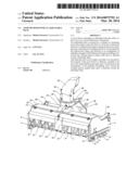
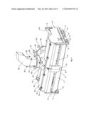
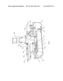
[0012] FIG. 1 is a perspective view of a snow blower comprising an adjustable back according to the embodiment of the present invention, and which a movable cover secured to the structure of the snow blower is in semi-upright position.
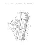
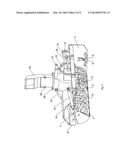
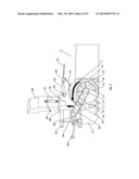
[0013] FIG. 2 is a side view of the snow blower comprising the adjustable back according to the embodiment of the present invention, and which in this position the adjustable back is used as rear wall of the snow blower.
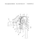
[0014] FIG. 3 is a side view of the snow blower when used backwards with a small amount of snow (A).
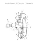
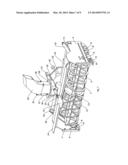
[0015] FIG. 4 is a perspective view of the snow blower comprising the adjustable back according to the embodiment of the present invention, and which in this position the adjustable back is used as front wall of the snow blower.
[0016] FIG. 5 is a side view of the snow blower comprising the adjustable back according to the embodiment of the present invention, and which in this position the adjustable back is used as front wall of the snow blower.
[0017] FIG. 6 is a side view of the snow blower when used forwards with a small amount of snow (B).
[0018] FIG. 7 is a perspective view of the snow blower comprising the adjustable back according to the embodiment of the present invention, and which in this position the adjustable back is used as rear wall of the snow blower.
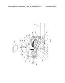
[0019] FIG. 8 is a side view of the snow blower comprising the adjustable back according to the embodiment of the present invention, and which in this position the movable cover secured to the structure of the snow blower is in raised position and the adjustable back is used as rear wall of the snow blower.
[0020] FIG. 9 is a side view of the snow blower when used backwards with a large amount of snow (C).
DETAILED DESCRIPTION
[0021] In the following description, as well as in the related views, the numbers refer to the numbered parts illustrated in the various figures.
[0022] Referring to the drawings and particularly to FIGS. 1-9, it is shown a snow blower including an adjustable back (1) that allows to blow snow in a forward direction or backwards.
[0023] The adjustable back (1) is actuated by a cylinder (10) or a hydraulic motor that makes rotate the back (1) in a forward or backward direction of a bidirectional auger (12) rotating clockwise for clearing snow collecting in its opening until snow is intercepted by the bidirectional auger (12) and to be directed on an arrangement of impellers (13) propelling arrow toward the rotating ejection pallets until snow is directed toward a discharge chute (29).
[0024] The arrangement of impellers (13) allows to improve the effectiveness of the loading of snow to the rotating ejection pallets.
[0025] The cylinder (10) used for the movement of the adjustable back (1) is arranged within the structure of the snow blower for protecting the cylinder against the external frictions and shocks, and that allows the user to pass more close to the low walls or the obstacles.
[0026] An interchangeable scraper blade (3) secured to the adjustable back (1) allows to scrape in a forward direction or backwards.
[0027] A gear wheel (17) is secured to one side (2) of the adjustable back (1) and to the bidirectional auger (12). The gear wheel (17) is joined to a gear wheel (16) by a drive chain (18). The gear wheel (16) is secured to a differential (25) and secured to the vehicle PTO by the PTO connection (26).
[0028] A movable cover (14) arranged above the bidirectional auger (12) is secured to the structure of the snow blower by hinges (21) and actuated by a cylinder (23) when the snow level is high to let snow fall on the bidirectional auger (12) and to be directed on the arrangement of the impellers (13) propelling snow toward the rotating ejection pallets until snow is directed toward the discharge chute (29) that is actuated by a cylinder (31) and oriented according to the desired direction by a motor (34). The cylinder (23) is secured to the structure of the snow blower and to a snow deflector (15) secured to the movable cover (14).
[0029] Each adjustable skid shoe (8) mounted under each of the sides (4) of the snow blower allows to scrape and push snow in the opening of the adjustable back in a forward direction or backwards.
[0030] A three-point fastener (27) is secured at the bottom of the discharge chute (29) and to the structure of the snow blower.
[0031] When the operator moves and blows snow in a forward direction with the vehicle which is attached the snow blower, the adjustable back (1) is to be the back wall of the snow blower for clearing snow collecting in its front opening until snow is intercepted by the bidirectional auger (12) and to be directed on the arrangement of the impellers (13) arranged on the bidirectional auger (12) propelling snow toward the rotating ejection pallets until snow is directed toward the discharge chute (29).
[0032] When the operator moves and blows snow backwards with the vehicle to which is attached the snow blower, the adjustable back (I) is to be the front wall of the snow blower for clearing snow collecting in its opening that is located rearwardly until snow is intercepted by the bidirectional auger (12) and to be directed on the arrangement of the impellers (13) arranged on the bidirectional auger (12) propelling snow toward the rotating ejection pallets until snow is directed toward the discharge chute (29).
[0033] Although the preferred form of embodiment of the invention is thoroughly described and illustrated hereto, it is understood that the invention is not limited to this particular form of embodiment and that many other modifications could be made without departing from the scope or spirit of the said invention.
[0034] Others forms of embodiment are possible but they must fall within the range of the following claims.
User Contributions:
Comment about this patent or add new information about this topic:
| People who visited this patent also read: | |
| Patent application number | Title |
|---|---|
| 20200259783 | METHOD AND APPARATUS FOR DETERMINING ETHERNET MAC ADDRESS |
| 20200259782 | SYSTEMS AND METHODS FOR MULTICAST DOMAIN NAME SYSTEM REDUNDANT QUERY SUPPRESSION |
| 20200259781 | 302 REDIRECTING METHOD, URL GENERATING METHOD AND SYSTEM, AND DOMAIN-NAME RESOLVING METHOD AND SYSTEM |
| 20200259780 | METHOD FOR DETECTING USER MIGRATION FROM ENTERPRISE NETWORK TO NON-ENTERPRISE NETWORK AND A DEVICE THEREOF |
| 20200259779 | SUPER CHAT |
Images included with this patent application:
 |  |
 |  |
 |  |
 |  |
 |  |
| Similar patent applications: | |
| Date | Title |
|---|---|
| 2013-10-03 | Snow plow rack and system |
| 2010-09-23 | Snowblower attachment |
| 2014-03-13 | Snow directing and discharging assembly |
| 2012-06-21 | Thumb with detachable body |
| 2013-06-27 | Adjustable blade rake |
| New patent applications in this class: | |
| Date | Title |
|---|---|
| 2016-05-19 | Self-propelled, single-stage snowthrower |
| 2016-02-11 | Snowblower skid shoe height adjustment mechanism |
| 2015-12-10 | Snow removal device |
| 2015-02-05 | Auger snow-removing machine |
| 2014-07-24 | Snow removal machine |
| Top Inventors for class "Excavating" | |
| Rank | Inventor's name |
|---|---|
| 1 | James Robert Lahood |
| 2 | Phillip J. Kunz |
| 3 | Robert N. Gamble, Ii |
| 4 | Mark D. Buckbee |
| 5 | Kent Winter |