Patent application title: Table apparatus for air movement
Inventors:
Timothy Paul Landvik (Port Angeles, WA, US)
Myrl J. Saarem (Carson City, NV, US)
Assignees:
Timothy Landvik
IPC8 Class: AA47B3704FI
USPC Class:
108 5013
Class name: Horizontally supported planar surfaces combined with heating or air moving means
Publication date: 2014-03-06
Patent application number: 20140060396
Abstract:
A table apparatus for distributing air or cooled air to those seated at
or near the table. The apparatus includes a motor, a fan and a means for
cooling air that is forced through upper and lower table portions.Claims:
1. An apparatus comprising: (a) a table comprising: (1) an upper portion,
(2) an exhaust panel structurally attached to said upper portion, (3) a
spacing means to separate said upper portion from said exhaust panel
comprising an air flow passageway between said upper portion and said
exhaust panel and an exhaust area around the perimeter of said upper
portion and said exhaust panel, (b) a base supporting said table, (c) a
motor, (d) a fan rotatably attached to said motor, whereby rotation of
said fan causes air to flow through said base, between said exhaust panel
and said upper portion of said table, and then to the surrounding
atmosphere.
2. The apparatus of claim 1 wherein said motor and said fan are structurally supported by said base.
3. The apparatus of claim 1 wherein said motor and said fan are structurally supported by said table.
4. The apparatus of claim 1 wherein the areas between said table exhaust panel and said table upper portion provide means for enhanced air flow.
5. The apparatus of claim 1 wherein the perimeter of said table contains exhaust means.
6. The apparatus of claim 1 wherein an evaporative cooling means is contained in said base.
7. The apparatus of claim 1 wherein an evaporative cooling means is contained in said table.
8. The apparatus of claim 6 or claim 7 wherein a water source connection is provided.
9. The apparatus of claim 6 or claim 7 wherein an electrically operated moisture dispensing means supplies control means for water supply to said evaporative cooling means.
10. The apparatus of claim 9 (claim 9 is a multiple dependent claim) wherein electrical power switching means supplies electric power to said moisture dispensing means and to said motor and that electric power is supplied to said moisture dispensing means only if electric power is being supplied to said motor.
Description:
BACKGROUND
[0001] 1. Field of Invention
[0002] This invention relates to an apparatus in the form of a table for moving air from surrounding atmosphere through the table and exhausting the air in a desired manner and direction. The air may be cooled as it passes through the table. This invention provides comfort to those in proximity of the table.
[0003] 2. Description of Prior Art
[0004] Air movement through a table is described U.S. Pat. No. 7,537,015. The table described has an umbrella, a table top, a base, a fan and a motor, and an air cooling means. Both the air entry and exhaust occur within the base.
PRESENT INVENTION
Objectives and Advantages
[0005] The present invention provides for convenient air flow and air cooling for those seated at or near the table invention, for example in a patio or deck.
DRAWING FIGURES
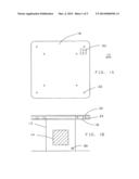
[0006] FIG. 1A and FIG. 1B are plan and side view of the invention.
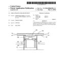
[0007] FIG. 2A and 2B are cross sections that show one configuration of the invention.
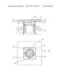
[0008] FIG. 3a and 3B show an alternate mounting means for the motor.
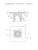
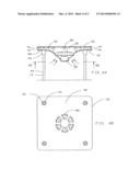
[0009] FIG. 4A and 4B show an alternate configuration of the table and the base.
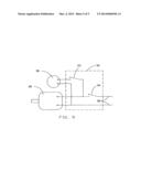
[0010] FIG. 5 shows a switching arrangement
DESCRIPTION
[0011] FIG. 1A and FIG. 1B show a plan view and front view, respectively, of the present invention 10. Base 12 has openings 14 on at least one side. The base 12 supports the lower portion 18 of the table 16. Lower portion 18 is attached to upper portion 20 by any convenient means, such as, but not limited to, screws 22 and dowels 24. Table 10 is shown essentially as square but can be rectangular, round, or any convenient shape.
[0012] FIG. 2A and FIG. 2B are cross sections of one example of the invention. Motor 26 is attached to base 12 by structures 28. Fan 30 is driveably attached to motor 26. Moisture dispensing tube 32 is arranged over, and allows moisture to disperse throughout excelsior (wood wool) pads 34 that are attached to base 12. The rate of dispersion is controlled by a moisture dispensing device 36, such as a solenoid valve, a rotating volume dispenser, or the like. The water input for device 36 is the water inlet 38 shown in FIG. 1B. When electric power causes motor 26 and fan 30 to rotate, air is drawn into base 12 through openings 14. Air passes through moist pads 34 and becomes humidified. The humid air then passes through fan 30, and exhausts between table lower portion 18 and table upper portion 20, thereby creating cool air around the perimeter of table 16.
[0013] FIG. 3a and FIG. 3B show the same detail as FIG. 2A and FIG. 2B with the exception that motor 26 and fan 30 are supported by structures 40 which are attached to the table lower portion 18.
[0014] FIG. 4A and FIG. 4B show a preferred embodiment of the invention. Table lower portion 18 is constructed of material (such as sheet metal or plastic) that can be formed into desirable configurations. Base 12 consists of sockets 42 that support legs 44. Fan 30 and motor 26 are supported by table lower portion 18, which contains air ports 48. Moisture pad 46 strategically occupies the space between table portions 18 and 20. Moisture pad 46 is made of porous material that can absorb moisture and can allow passage of air. Moisture dispensing tube 32 is dispersed throughout the moisture pad 46 and is controlled by moisture dispensing device 36. When electric power causes motor 26 and fan 30 to rotate, atmospheric air is drawn through air ports 48 and through fan 30 and forced through moisturized pad 46 and exhaust between table lower portion 18 and table upper portion 20, thereby creating cool air around the perimeter of table 16.
[0015] FIG. 4 shows a switching arrangement 50 wherein moisture dispensing device 36 can only receive electrical power if motor 26 is receiving electrical power.
Conclusion
[0016] Accordingly, this invention offers a unique means of providing comfort and enjoyment to those utilizing a table in an outdoor environment.
[0017] It will be appreciated that while particular embodiments of the invention have been shown and described, modifications may be made. It is intended in the claims to cover all modifications that come within the true spirit and scope of the invention.
User Contributions:
Comment about this patent or add new information about this topic:
Images included with this patent application:
 |  |
 |  |
 |  |
| Similar patent applications: | |
| Date | Title |
|---|---|
| 2014-04-17 | Table apparatus |
| 2014-06-12 | Adjustable desk platform |
| New patent applications in this class: | |
| Date | Title |
|---|---|
| 2016-06-16 | Fire pit table with lazy susan tabletop portion |
| 2016-04-14 | Visual display system for a high-gain reflective beam-splitter |
| 2016-03-31 | Laptop ventilated computer table |
| 2014-02-13 | Outdoor tables with heater access |
| 2012-12-20 | Table and fan combo |
| Top Inventors for class "Horizontally supported planar surfaces" | |
| Rank | Inventor's name |
|---|---|
| 1 | Mitch Johnson |
| 2 | Wendell Peery |
| 3 | David C. Winter |
| 4 | William P. Apps |
| 5 | Mustafa A. Ergun |