Patent application title: METHOD AND APPARATUS FOR HETERODYNE COHERENT DETECTION
Inventors:
Jianjun Yu (Basking Ridge, NJ, US)
Jianjun Yu (Basking Ridge, NJ, US)
Ze Dong (Morristown, NJ, US)
Ze Dong (Morristown, NJ, US)
Hung-Chang Chien (Bridgewater, NJ, US)
Hung-Chang Chien (Bridgewater, NJ, US)
Assignees:
ZTE (USA) INC.
IPC8 Class: AH04J1408FI
USPC Class:
370542
Class name: Communication techniques for information carried in plural channels combining or distributing information via time channels demultiplexing single input channel to plural output channels
Publication date: 2014-02-20
Patent application number: 20140050233
Abstract:
A simplified coherent receiver based on heterodyne detection with only
two balanced photo detectors (PD) and two analog-to-digital converters
(ADC) is disclosed. The polarization diversity hybrid can be simplified
relative to the conventional one. The detected intermediate frequency
signals are first down converted to baseband with I/Q separation.Claims:
1. A method of detecting an optical signal, the method comprising:
demultiplexing, by at least one optical filter, the optical signal into a
plurality of signals; splitting, by at least one beam splitter, each of
the plurality of signals into polarization components of each of the
plurality of signals respectively; applying a lightwave from one local
oscillator to the respective polarization components of at least two of
the plurality of signals to create respective mixed polarization
components; and detecting, by at least one photodiode, the respective
mixed polarization components.
2. The method of claim 1, wherein the at least one optical filter comprises one of a group of: an arrayed waveguide grating filter and a wave division multiplexed filter.
3. The method of claim 1, wherein a wavelength of the lightwave from the one local oscillator is the middle wavelength of the center wavelength of the respective polarization components of each of the plurality of signals.
4. The method of claim 1, further comprising dividing, by an optical coupler, the lightwave into two parts, wherein one of the two parts is applied to each of the plurality of signals to create respective mixed polarization components.
5. The method of claim 4, wherein the optical coupler is a polarization maintaining optical coupler.
6. An apparatus for detecting an optical signal, the apparatus comprising: means for demultiplexing the optical signal into a plurality of signals; means for splitting each of the plurality of signals into polarization components of each of the plurality of signals respectively; means for applying a lightwave to the respective polarization components of at least two of the plurality of signals to create respective mixed polarization components; and means for detecting the respective mixed polarization components.
7. The apparatus of claim 6, wherein a wavelength of the lightwave is the middle wavelength of the center wavelength of the respective polarization components of each of the plurality of signals.
8. The apparatus of claim 6, further comprising means for dividing the lightwave into two parts, wherein one of the two parts is applied to each of the plurality of signals to create respective mixed polarization components.
9. The apparatus of claim 8, wherein the optical coupler is a polarization maintaining optical coupler.
10. A system for detecting an optical signal, the system comprising: at least one optical filter configured to demultiplex the optical signal into a plurality of signals; at least one beam splitter configured to split each of the plurality of signals into polarization components of each of the plurality of signals respectively; one local oscillator configured to apply a lightwave to the respective polarization components of at least two of the plurality of signals to create respective mixed polarization components; and at least one photodiode configured to detect the respective mixed polarization components.
11. The system of claim 10, wherein the at least one optical filter comprises one of a group of: an arrayed waveguide grating filter and a wave division multiplexed filter.
12. The system of claim 10, wherein a wavelength of the lightwave from the one local oscillator is the middle wavelength of the center wavelength of the respective polarization components of each of the plurality of signals.
13. The system of claim 10, further comprising dividing, by an optical coupler, the lightwave into two parts, wherein one of the two parts is applied to each of the plurality of signals to create respective mixed polarization components.
14. The system of claim 13, wherein the optical coupler is a polarization maintaining optical coupler.
Description:
CROSS-REFERENCE TO RELATED APPLICATIONS
[0001] The present application claims benefit to U.S. Provisional Application No. 61/683,028, filed Aug. 14, 2012.
BACKGROUND OF THE INVENTION
[0002] With the development of electronic analog-to-digital converter (ADC) and photo detectors (PD) in bandwidth and speed, coherent detection with digital signal processing (DSP) has been attracting a great deal of interest again in recent years [1-4]. Thanks to DSP technology, optical transmission impartments can be equalized in electrical domain [2]. Homodyne detection has been discussed and investigated a lot in recent coherent communication system due to DSP in electrical domain [1-4]. However, inphase and quadrature (I/Q) signals should be separated in optical domain with full information. In this way, 4 balanced detectors with double hybrid structures and 4 channels ADCs are required.
[0003] Heterodyne coherent detection can simplify the coherent receiver with only half of the PDs and ADCs [1, 5]. The optical hybrid can be also simplified. However, this technique is limited by the bandwidth of PDs or ADCs which should have wider bandwidth for intermediate frequency (IF) signals. Thanks to the development of the PDs and ADCs, it gives a possibility to achieve a simplified coherent receiver with heterodyne detection, which has been investigated in subcarrier multiplexing system [6, 7] and radio over fiber system [8]. The most recent report on heterodyne detection is a limited 5 Gb/s 4 QAM signal over 20 km in [6] and limited 20 Mbaud 64 and 128 QAM over 525 km in [7].
BRIEF SUMMARY OF THE INVENTION
[0004] In this disclosure, we propose and experimentally demonstrate a simplified coherent receiver based on heterodyne detection with only two balanced photo detectors (PD) and two ADCs. The polarization diversity hybrid can be simplified relative to the conventional one. The detected intermediate frequency signals are first down converted to baseband with I/Q separation.
BRIEF DESCRIPTION OF THE DRAWINGS
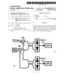
[0005] FIG. 1(a) shows the principle of simplified coherent receiver with heterodyne detection.
[0006] FIG. 1(b) also shows the principle of simplified coherent receiver with heterodyne detection.
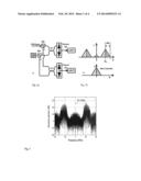
[0007] FIG. 2 shows the electrical spectrum of received IF signals with 22 GHz frequency offset after balanced detector and band-pass EA.
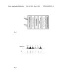
[0008] FIG. 3 shows digital signal processing for received signals after ADCs.
[0009] FIG. 4 shows homodyne coherent detection.
[0010] FIG. 5 shows heterodyne coherent detection (regular scheme).
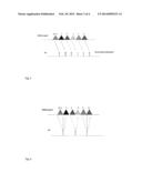
[0011] FIG. 6 shows heterodyne coherent detection with the proposed scheme.
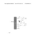
[0012] FIG. 7 shows details of heterodyne coherent detection.
DETAILED DESCRIPTION OF THE INVENTION
[0013] FIG. 1 shows the principle of proposed simplified coherent receiver with heterodyne detection. The proposed coherent receiver consists of two polarization beam splitter (PBS) for PDM signal and LO polarization diversity splitting, two optical couplers (OC) and two balanced PDs. We can see that only two balanced receivers and ADCs are needed. The polarization diversity hybrid is also simplified relative to conventional one. The I/Q signals are received at the same time at the intermediate frequency (IF) as shown in FIG. 1 (b). Here, the LO has a large frequency offset of fIF=fs-fLO to the signal and BW is the bandwidth of baseband signal. The IF signal can be down converted to base band in the electrical domain. After polarization splitter, the signal of one polarization can be expressed as
Es= {square root over (Ps)}exp [j2πfst+φs(t)] (1)
[0014] where fs is the optical frequency of signal, Ps is the signal power, and φs is phase information of signal. The LO can be also expressed as
ELO= {square root over (PLO)}exp[j2πfLOt+φLO(t)] (2)
[0015] where fLO is the optical frequency of LO, PLO is the power, and φLO is phase of LO. After the balanced photo detection, the alter-current (AC) from the balanced PDs without direct current (DC) part can be expressed as
BPD=2R {square root over (PsPLO)} cos [2πfIFt+φs(t)-φLO(t)] (3)
[0016] where R is the detector responsivity, and fIF=fs-fLO is IF or frequency offset of the LO and signal. The output current of balanced PD for the other polarization is similar to Eq. 3. For heterodyne detection with only two balanced PDs, in order to separate the I and Q part without crosstalk, the IF should fIF≧BW. Otherwise, it is not possible to separate I and Q part with only two balanced PDs without crosstalk. As analyzed in [5], assuming the ζ is the noise density of signal, the SNR for heterodyne detection is
SNR He = S He N He = 2 × 0.5 I BPD 2 2 B W ζ = 2 P S P LO R 2 / B W ζ ( 4 ) ##EQU00001##
[0017] However, for homodyne detection, a conventional 4*90° hybrid is needed with fIF=fs-fLO=0. In this way, the I or Q part of signal can be expressed as
IBPD--.sub.ilq=2R {square root over (PsPLO)} cos [φs(t)-φLO(t)] (5)
[0018] In this way, the SNR for homodyne detection is [5]
SNR Ho = S Ho N Ho = I BPD_i / q 2 B W ζ = 4 P S P LO R 2 / B W ζ ( 6 ) ##EQU00002##
[0019] which shows 3 dB SNR improvement compared with heterodyne detection. However, the homodyne detection cannot use the simplified 180° optical hybrid and only two balanced PDs and ADCs without destroying the I/Q information. FIG. 2 shows the electrical spectrum after heterodyne coherent detection when the LO is 22 GHz away from the detected channel.
[0020] FIG. 3 shows the offline digital signal processing for received signals after ADCs. The received signals are first down converted to baseband by frequency shifting. The compensation of chromatic dispersion (CD) is based on the known fiber CD transfer function in frequency-domain as the next step. The I/Q is separated as the subsequent step before the polarization de-multiplexing. Two complex-valued, 13-tap, T/2-spaced adaptive FIR filters, based on the classic constant modulus algorithm (CMA), are used to retrieve the modulus of the PDM- QPSK signal. The carrier recovery is performed in the subsequent step, where the 4-th power is used to estimate the frequency offset between the LO and the received optical signal. After frequency offset compensation, the phase recovery is obtained from the speed of the phase rotation using the 4th-power algorithm. Finally, differential decoding is used for bit-error-rate (BER) calculating after decision.
Homodyne Coherent Detection
[0021] Each WDM channel needs one individual local oscillator (LO) laser. For example, six WDM channels need six LO lasers. Usually the center wavelength of the LO should be equal to the center wavelength of the matched channel.
Heterodyne Coherent Detection (Regular Scheme)
[0022] For heterodyne coherent detection, the LO laser should be set some distance away from the center wavelength of the matched WDM channel. Each WDM channel should have one Individual LO laser as shown in the figure.
Heterodyne Coherent Detection with Proposed Scheme
[0023] In the proposed new scheme, we will reduce number of the LO laser. Here we use one LO laser for two different WDM channels. Such as LO 1 is used for channel 1 and channel 2. Here the wavelength of the LO1 is in the middle wavelength of channel 1 and channel 2. By this way we can reduce the number of the LO lasers. For example, if channel spacing of the WDM channel is 25 GHz, we will set each LO is 12.5 GHz away the neighboring WDM channels. If the center frequency of ch1 and ch 2 is f and f+25, then LO frequency is f+12.5 GHz.
[0024] As one example, we show heterodyne coherent channel 1 and 2. The WDM signals are demultiplexed by using one optical filter such as arrayed waveguide grating filter, WDM filter, or other optical filter. Here the heterodyne architecture is quite normal, not special. For example the polarization multiplexed channel 1 is divided into two parts by one optical polarization beam splitter, then we combine X or Y polarization component of LO1 by using one optical coupler before they are detected by a photodiode. Channel 1 and channel 2 share the LO1. Here the lightwave from LO1 is divided into two parts by using one polarization maintaining optical coupler (PM OC), and the wavelength of LO1 is the middle wavelength of the center wavelength of channel 1 and 2.
[0025] It should be understood that the methods and devices of the present invention may be executed employing machines and apparatus including simple and complex computers. Moreover, the architecture and methods described above can be stored, in part or in full, on forms of machine-readable media. For example, the operations of the present invention could be stored on machine-readable media, such as magnetic disks or optical disks, which are accessible via a disk drive (or computer-readable medium drive). Alternatively, the logic to perform the operations as discussed above, could be implemented in additional computer and/or machine readable media, such as discrete hardware components as large-scale integrated circuits (LSI's), application-specific integrated circuits (ASIC's), firmware such as electrically erasable programmable read-only only memory (EEPROM's); and the like. Implementations of certain embodiments may further take the form of machine-implemented, including web-implemented, computer software.
[0026] Many modifications and alterations of the new methods and systems described herein may be employed by those skilled in the art without departing from the spirit and scope of the invention which is limited only by the claims.
REFERENCES
[0027] E. Ip, A. P. T. Lau, D. J. F. Barros, J. M. Kahn, Opt. Express 16, 753-791 (2008)
[0028] S. J. Savory, J. of Selected Topics in Quantum Electronics, 16, 1164-1179 (2010)
[0029] X. Zhou, J. Yu, J. Lightw. Technol., 27, 3641-3653 (2009)
[0030] J. Yu, Z. Dong, H. Chien, Y., and N. Chi., IEEE Photon. Technol. Lett., 24, 264-266 (2012)
[0031] L. G. Kazovsky, J. Opt. Commun 1, 18-24 (1985)
[0032] R. Zhu, K. Xu, Y. Zhang, Y. Li, J. Wu, X. Hong, J. Lin, in Proc. Of APMP, 165-168 (2008)
[0033] M. Nakazawa, M. Yoshida, K. Kasai and J. Hongou. Electronic Lett. 42, 12 (2006)
[0034] X. Pang, A. Caballero, A. Dogadaev, IEEE Photonics Journal, vol. 4, no. 3, pp. 691-698, 2012.
User Contributions:
Comment about this patent or add new information about this topic:
| People who visited this patent also read: | |
| Patent application number | Title |
|---|---|
| 20150086752 | APPARATUS FOR LAMINATING THERMOPLASTIC FILM MATERIALS |
| 20150086751 | Laminates, and Systems and Methods for Laminating |
| 20150086750 | BULK TEXTURED MATERIAL SHEETING |
| 20150086749 | RELEASE FILM FOR PRODUCING GREEN SHEET |
| 20150086748 | HONEYCOMB STRUCTURE |
Images included with this patent application:
 |  |
 |  |
 |
| Similar patent applications: | |
| Date | Title |
|---|---|
| 2009-08-06 | Energy aware early detection |
| 2013-09-26 | Method and apparatus for control plane cpu overload protection |
| 2013-10-24 | Chunk-based double-dwell preamble detection |
| 2013-12-12 | Voice conference unit selection |
| 2013-12-26 | Method and apparatus for machine-to-machine event data recording |
| New patent applications in this class: | |
| Date | Title |
|---|---|
| 2015-12-24 | Data processing devices and data processing methods |
| 2015-05-21 | Recycled-carrier modulation |
| 2015-05-07 | Optical mode steering for wavelength stabilization |
| 2015-03-26 | Wavelength-selective switch for space-division multiplexed systems |
| 2015-03-12 | System and method using cascaded single partity check coding |
| New patent applications from these inventors: | |
| Date | Title |
|---|---|
| 2019-10-17 | Amplitude coherent detection for pulse amplitude modulation signals |
| 2018-06-07 | Chirp managed laser generation for next generation passive optical networks |
| 2017-06-22 | Techniques for receiving dft spreading modulation signals |
| 2017-06-15 | Training assisted joint equalization |
| Top Inventors for class "Multiplex communications" | |
| Rank | Inventor's name |
|---|---|
| 1 | Peter Gaal |
| 2 | Wanshi Chen |
| 3 | Tao Luo |
| 4 | Hanbyul Seo |
| 5 | Jae Hoon Chung |