Patent application title: SWITCH FOR A TRANSMISSION PATH FOR HIGH-VOLTAGE DIRECT CURRENT
Inventors:
Werner Hartmann (Weisendorf, DE)
Werner Hartmann (Weisendorf, DE)
Lutz-Ruediger Jaenicke (Mahlow, DE)
Sylvio Kosse (Erlangen, DE)
Sylvio Kosse (Erlangen, DE)
Reinhard Maier (Herzogenaurach, DE)
Anthoula Panagou (Zuerich, CH)
Norbert Trapp (Berlin, DE)
Assignees:
SIEMENS AKTIENGESELLSCHAFT
IPC8 Class: AH02H308FI
USPC Class:
361 87
Class name: Safety and protection of systems and devices with specific quantity comparison means current
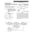
Publication date: 2014-01-16
Patent application number: 20140016236
Abstract:
A switch for a high-voltage direct current transmission path includes a
vacuum circuit breaker for disconnecting the transmission path and a
gas-insulated circuit breaker for disconnecting the transmission path.
The gas-insulated circuit breaker is connected in series with the vacuum
circuit breaker. A device is provided for building up a counter-current
against the current in the transmission path for the purpose of reducing
the current across the vacuum circuit breaker. The elements of the switch
are actuated by a control device in such a way that the switch is
switched off at or close to the zero crossing of the current.Claims:
1-10. (canceled)
11. A switch for a high-voltage direct current transmission path, the switch comprising: a series circuit including a first switching device and a second switching device, said first switching device configured for interrupting current and said second switching device configured for voltage isolation; and a device configured for building up a counter-current against a current in the transmission path for reducing a current through said switching devices.
12. The switch according to claim 11, wherein said first switching device has a vacuum circuit breaker.
13. The switch according to claim 11, wherein said second switching device has a gas-insulated, oil-insulated or low-oil-content circuit breaker.
14. The switch according to claim 11, wherein said device for building up a counter-current is connected in parallel with said first switching device and includes a high-voltage capacitor and a third switching device connected in series with said high-voltage capacitor.
15. The switch according to claim 14, wherein said third switching device is a thyristor.
16. The switch according to claim 14, wherein said third switching device is a gas-insulated circuit breaker.
17. The switch according to claim 11, which further comprises a device connected in series with said first switching device for limiting a current rise.
18. The switch according to claim 17, wherein said device for limiting a current rise includes an inductance in series with a parallel circuit having a nonlinear inductance and a capacitance.
19. The switch according to claim 11, which further comprises a control device configured to determine a change in a current with respect to time and to determine therefrom a presence of a short circuit and, if a short circuit is present, to output control signals causing said first switching device to open.
20. The switch according to claim 19, wherein said control device is configured to drive said device for building up a counter-current, if a short circuit is present, to build up a counter-current and to drive said first switching device to switch off at a lowest possible magnitude of a current.
21. The switch according to claim 20, wherein said lowest possible magnitude of the current is a zero crossing of the current.
Description:
[0001] The invention relates to a switch for a transmission path for
high-voltage direct current transmission.
[0002] Circuit breakers are required for high-voltage direct current transmission (HVDC), in particular for establishing HVDC multi-terminal and HVDC network systems. Said circuit breakers have to be able to reliably switch off both the rated currents and short-circuit currents. Present rated voltages are 550 kV. In the future the rated voltages may reach 800 kV or even 1000 kV. The rated currents are approximately 2 to 5 kA. The short-circuit currents to be switched off can amount to a multiple of the rated current. A circuit breaker for high-voltage direct current transmission must additionally ensure galvanic isolation. Previous HVDC installations have been embodied as point-to-point solutions. Shutdowns of these installations are performed by a closed-loop control of the respective convertor stations.
[0003] It is an object of the present invention to specify a switch for a transmission path for high-voltage direct current with which rated and short-circuit currents can reliably be switched off in conjunction with the simplest possible construction.
[0004] This object is achieved by means of a switch comprising the features of claim 1. The dependent claims relate to advantageous embodiments of the switch.
[0005] The switch according to the invention for a transmission path for high-voltage direct current comprises a series circuit comprising a first and a second switching device, wherein the first switching device is designed for interrupting current and the second switching device is designed for voltage isolation. Finally, the switch comprises a device for building up a counter-current against the current in the transmission path for the purpose of reducing the current through the switching devices. In this case, the first switching device preferably comprises a vacuum circuit breaker. The second switching device preferably comprises a gas-insulated, oil-insulated or low-oil-content circuit breaker.
[0006] For the invention it has been recognized that, advantageously, an improvement in the switching process can achieved by generating a counter-current that reduces the current flowing through the vacuum circuit breaker. In particular, a zero crossing of the current is generated in this case. This is possible since the polarity is known from the outset in the case of the HVDC installation, and does not change continuously, as in the case of alternating current.
[0007] Preferably, the device for building up a counter-voltage comprises a high-voltage capacitor and a switch. It is expedient if the elements are connected in parallel with the vacuum circuit breaker. In this case, in normal operation the high-voltage capacitor is charged, but is electrically decoupled at least on one side by the switch. If a current reduction is intended to take place, the switch is closed. The switch used can be a semiconductor switch such as a thyristor, for example, or else a second gas-insulated circuit breaker.
[0008] Preferably, the device for building up a counter-current comprises a high-voltage capacitor and a third switching device in series therewith and is connected in parallel with the first switching device. The third switching device used can be, for example, a thyristor or a further gas-insulated circuit breaker.
[0009] In one advantageous embodiment and development of the invention, the switch comprises a device for limiting the current rise connected in series with the first switching device. Said device can comprise, for example, an inductance in series with a parallel circuit comprising a nonlinear inductance and a capacitance. This advantageous solution obviates the cost- and energy-intensive superconducting solutions known from the prior art, which also always require a failsafe cryogenic engineering system.
[0010] The switch expediently comprises a control device. The latter is preferably designed to determine the change in the current with respect to time and to determine therefrom the presence of a short circuit, and, if a short circuit is present, to output control signals such that the first switching device is opened. The control device is furthermore preferably designed to drive the device for building up a counter-current, if a short circuit is present, to build up a counter-current and to drive the vacuum circuit breaker to switch off the current at the lowest possible magnitude of the current, in particular at a zero crossing of the current.
[0011] In a further embodiment of the invention, the control device sets the level of the counter-voltage on the basis of the measured change in the current. This results in a fast and reliable switch-off by the vacuum circuit breaker.
[0012] Preferred, but in no way restrictive, exemplary embodiments of the invention will now be explained in greater detail with reference to the figures of the drawing. In this case, the features are illustrated schematically. In the Figures:
[0013] FIG. 1 shows a schematic construction of a switch for a high-voltage direct current transmission path,
[0014] FIG. 2 shows a construction for a current change limiter,
[0015] FIG. 3 shows a construction for a device for generating a counter-current.
[0016] FIG. 1 schematically shows the construction for an exemplary embodiment of a switch. The switch is arranged in a high-voltage direct current transmission path 1 and can be connected to further lines by a terminus 2. The switch comprises a vacuum circuit breaker 3. The vacuum circuit breaker 3 is realized in a known manner.
[0017] Furthermore, the switch comprises a device 4 for generating a counter-current. One exemplary embodiment of such a device 4 for generating a counter-current is illustrated in FIG. 3. The device 4 for generating a counter-current comprises a high-voltage capacitor 21 and a thyristor 22 connected in series. As an alternative to the thyristor 22, here it is also possible to use some other semiconductor switch, such as an IGBT, for example.
[0018] The switch furthermore comprises a current change limiter 6. An exemplary construction for the current change limiter 6 is illustrated in FIG. 2. In this case, the current change limiter 6 comprises a parallel circuit comprising a nonlinear inductance 12 and a capacitor 13. This parallel circuit, for its part, is connected in series with a further inductance 11.
[0019] Furthermore, the switch comprises a gas-insulated circuit breaker 5, for example an SF6 circuit breaker. The gas-insulated circuit breaker 5, the vacuum circuit breaker 3 and current change limiter 6 are in this case connected in series. The device 4 for generating a counter-current is arranged in parallel with the vacuum circuit breaker 3.
[0020] Where necessary, a control device 7 is connected to the abovementioned elements. Thus, in this exemplary embodiment there is a connection from the control device 7 to the current change limiter 6, via which the control device 7 receives a measurement signal for the current change dI/dt. There is a further control connection between the control device 7 and the vacuum circuit breaker 3, and between the control device 7 and the device 4 for generating a counter-current. Finally, there is a connection between the control device 7 and the gas-insulated circuit breaker 5.
[0021] During operation, the control device 7 monitors the measured values for the change in the current with respect to time. In the case of a short circuit, the flowing current would rise greatly. The current change limiter 6 prevents this great rise for the time being. The control device 7 recognizes the presence of a short circuit from the current that is nevertheless rising. As a consequence, the control device 7 generates switching commands for the further elements of the switch. These control commands consist in opening the vacuum circuit breaker 3 and the gas-insulated circuit breaker 5, and in switching on the thyristor 22 in the device 4 for generating a counter-current. In this case, the control device 7 defines the temporal sequence of these commands. Expediently, a counter-current is generated rapidly. In this case, the generation of the counter-current is controlled in such a way that ideally a current zero crossing occurs. At the current zero crossing or close to the current zero crossing, the vacuum circuit breaker 3 is switched off. An additional switching-off of the gas-insulated circuit breaker 5 provides for the ultimately high dielectric strength and ensures that reignition does not take place in the vacuum circuit breaker 3.
User Contributions:
Comment about this patent or add new information about this topic:
Images included with this patent application:
 |  |
| New patent applications in this class: | |
| Date | Title |
|---|---|
| 2017-08-17 | Electronic circuit for single-event latch-up detection and protection |
| 2016-06-30 | Temperature-compensated current monitoring |
| 2016-06-23 | Residual current devices |
| 2016-06-23 | Circuit interruption apparatus providing automatic reduced arc mode and methods of operating the same |
| 2016-06-09 | Circuit and method for measuring a current |
| New patent applications from these inventors: | |
| Date | Title |
|---|---|
| 2022-09-15 | Switching device comprising two interrupter units connected in series |
| 2022-07-07 | Circuit breaker |
| 2022-03-10 | Motor apparatus for a switch drive of an electrical switch |
| 2021-06-17 | Arrangement and method for switching high voltages having a switching device and precisely one resistor stack |
| 2017-01-26 | Apparatus and method for dynamically adjusting an electric arc furnace |
| Top Inventors for class "Electricity: electrical systems and devices" | |
| Rank | Inventor's name |
|---|---|
| 1 | Zheng-Heng Sun |
| 2 | Levi A. Campbell |
| 3 | Li-Ping Chen |
| 4 | Robert E. Simons |
| 5 | Richard C. Chu |