Patent application title: PROCESS FOR THROTTLING A COMPRESSED GAS FOR EVAPORATIVE COOLING
Inventors:
Jiri Polansky (Pilsen, CZ)
Lukas Choulik (Pilsen, CZ)
Jorge E. Pacheco (Olean, NY, US)
Assignees:
DRESSER-RAND COMPANY
IPC8 Class: AF25B110FI
USPC Class:
62115
Class name: Refrigeration processes compressing, condensing and evaporating
Publication date: 2013-12-19
Patent application number: 20130333403
Abstract:
A system and method of cooling a compressed working fluid is disclosed.
The method includes compressing the working fluid above its critical
pressure point in a compression stage to generate a compressed working
fluid at or about local ambient temperature. The compressed working fluid
can be cooled to below ambient by throttling a portion of the compressed
working fluid to its saturated liquid-vapor state to generate a recycle
working fluid. The recycle working fluid may then be atomized using an
atomizing nozzle whereby the recycle working fluid evaporates and cools
working fluid entering a target compression stage.Claims:
1. A system for cooling a compressed working fluid, comprising: a
compressor having a series of compression stages for compressing a
working fluid, the series of compression stages including an evaporative
compression stage and a target compression stage, wherein the evaporative
compression stage compresses the working fluid to at least a critical
pressure; a series of heat exchangers fluidly coupled to the series of
compression stages such that at least one heat exchanger interposes
adjacent compression stages, the series of heat exchangers being
configured to decrease a temperature of the working fluid discharged from
a preceding compression stage; a valve fluidly coupled to a heat
exchanger following the evaporative compression stage, the valve being
configured to throttle a portion of the working fluid to at least its
saturated liquid-vapor state; and a fogging device fluidly coupled to the
valve and the target compression stage, the fogging device being
configured to evaporate the portion of the working fluid to evaporatively
cool the working fluid entering the target compression stage.
2. The system of claim 1, wherein the compressor is a centrifugal compressor.
3. The system of claim 1, wherein the working fluid is carbon dioxide.
4. The system of claim 1, wherein the series of heat exchangers are water-cooled or air-cooled heat exchangers.
5. The system of claim 1, wherein the series of heat exchangers are configured to reduce the temperature of the working fluid to at or near ambient temperature.
6. The system of claim 1, wherein the valve further throttles the portion of the working fluid to at or near a suction pressure of the target compression stage.
7. The system of claim 1, wherein the fogging device has an atomizing nozzle that atomizes the portion of the working fluid in the presence of the working fluid.
8. The system of claim 7, wherein the fogging device reduces the temperature of the working fluid to below ambient temperature.
9. The system of claim 1, wherein the evaporative compression stage and the target compression stage are the same compression stage.
10. A method of cooling a compressed working fluid, comprising: compressing a working fluid in a series of compression stages, the series of compression stages including an evaporative compression stage and a target compression stage; cooling the working fluid in a series of heat exchangers fluidly coupled to the series of compression stages, wherein at least one heat exchanger is interposed between each compression stage and each heat exchanger is configured to decrease a temperature of the working fluid discharged from a preceding compression stage; compressing the working fluid to at least a critical pressure in the evaporative compression stage; throttling a portion of the working fluid discharged from the evaporative compression stage with a valve fluidly coupled to the evaporative compression stage, the portion of the working fluid being throttled to at least its saturated liquid-vapor state; and atomizing the portion of the working fluid with a fogging device fluidly coupled to the valve and the target compression stage, whereby the portion of the working fluid evaporates and cools the working fluid entering the target compression stage.
11. The method of claim 10, wherein cooling the working fluid in a series of heat exchangers further comprises cooling the working fluid discharged from a preceding compression stage to at or near ambient temperature.
12. The method of claim 10, further comprising throttling the portion of the working fluid to at or near a suction pressure of the target compression stage.
13. The method of claim 10, wherein the fogging device comprises an atomizing nozzle.
14. The method of claim 13, further comprising atomizing the portion of the working fluid with the atomizing nozzle.
15. The method of claim 10, further comprising evaporatively cooling the working fluid entering the target compression stage to below ambient temperature.
16. A method of cooling a working fluid in a compressor, comprising: compressing the working fluid above a critical pressure in a first compression stage to generate a compressed working fluid; throttling a portion of the compressed working fluid to its saturated liquid-vapor state to generate a recycle working fluid; atomizing the recycle working fluid with an atomizing nozzle whereby the recycle working fluid evaporates and cools; and injecting the recycle working fluid at a suction inlet of a target compression stage to cool the working fluid therein.
17. The method of claim 16, wherein the working fluid is carbon dioxide.
18. The method of claim 16, further comprising throttling the portion of the compressed working fluid to at or near a suction pressure of the second compression stage.
19. The method of claim 16, wherein the target compression stage is the first compression stage.
20. The method of claim 16, further comprising cooling the working fluid entering the second compression stage to below ambient temperature.
21-37. (canceled)
Description:
CROSS-REFERENCE TO RELATED APPLICATIONS
[0001] The present application claims priority to U.S. Provisional Patent Application Ser. No. 61/376,133 entitled "Process for Throttling a Compressed Gas for Evaporative Cooling," which was filed on Aug. 23, 2010. The contents of the priority application are hereby incorporated by reference into the present disclosure in their entirety.
BACKGROUND
[0002] As a compressor increases the pressure of a working fluid, the temperature of the working fluid and the components of the compressor also increases. Increased temperatures oftentimes decrease compressor efficiency by amplifying the amount of work required to compress the fluid. This can result in damage to or premature failure of compressor components. To avoid compressor damage and simultaneously increase its efficiency, several cooling strategies are typically employed to achieve a more iso-thermal compression process.
[0003] For example, one common cooling strategy includes a continuous cooling system, where there is no direct contact between the incoming working fluid and the cooling medium. In a typical continuous cooling system arrangement, a finite number of compression stages are equipped with a series of external heat exchangers interposed between each stage and configured to intercool the working fluid to at or near local ambient conditions. Decreasing the temperature of the cooling medium to below local ambient, however, requires additional work and results in an increased power demand and decreased efficiency.
[0004] Another common compressor cooling strategy is evaporative cooling where cooling is achieved by directly mixing the working fluid with the cooling medium. In a typical evaporative cooling arrangement, the cooling medium is injected directly into the gas loop of the compressor where it is atomized and evaporated into the working fluid. In operation, the evaporative cooling strategy relies on the evaporation and adiabatic saturation of the cooling medium to decrease the temperature of the working fluid.
[0005] While there are several compressor cooling strategies known, it is nonetheless desirable to find improved and more efficient methods of cooling.
SUMMARY
[0006] Embodiments of the disclosure may provide a system for cooling a compressed working fluid. The system may include a compressor having a series of compression stages for compressing a working fluid, the series of compression stages including an evaporative compression stage that compresses the working fluid to at least a critical pressure, and a series of heat exchangers fluidly coupled to the series of compression stages, wherein at least one heat exchanger is interposed between each compression stage and configured to decrease a temperature of the working fluid discharged from a preceding compression stage. The system may also include a valve communicably coupled to the at least one heat exchanger following the evaporative compression stage and configured to receive and throttle a portion of the working fluid as a recycle working fluid, wherein the valve throttles the recycle working fluid to at least its saturated liquid-vapor state, and a fogging device fluidly coupled to the valve and a target compression stage, the fogging device being configured to receive the recycle working fluid and evaporatively cool the working fluid entering the target compression stage.
[0007] Embodiments of the disclosure may further provide a method of cooling a compressed working fluid. The method may include compressing a working fluid in a series of compression stages, the series of compression stages including an evaporative compression stage that compresses the working fluid to at least a critical pressure, and cooling the working fluid in a series of heat exchangers fluidly coupled to the series of compression stages, wherein at least one heat exchanger is interposed between each compression stage and each heat exchanger is configured to decrease a temperature of the working fluid discharged from a preceding compression stage. The method may also include throttling a portion of the working fluid discharged from the evaporative compression stage to at least its saturated liquid-vapor state with a valve fluidly coupled to the evaporative compression stage, and atomizing the portion of the working fluid with a fogging device fluidly coupled to the valve and a target compression stage. The method may further include evaporatively cooling the working fluid entering the target compression stage.
[0008] Embodiments of the disclosure may further provide another method of cooling a working fluid in a compressor. The method may include compressing the working fluid above a critical pressure in a first compression stage to generate a compressed working fluid, and throttling a portion of the compressed working fluid to its saturated liquid-vapor state to generate a recycle working fluid. The method may further include atomizing the recycle working fluid with an atomizing nozzle whereby the recycle working fluid evaporates and cools, injecting the recycle working fluid at a suction inlet of a target compression stage to cool the working fluid therein.
BRIEF DESCRIPTION OF THE DRAWINGS
[0009] The present disclosure is best understood from the following detailed description when read with the accompanying Figures. It is emphasized that, in accordance with the standard practice in the industry, various features are not drawn to scale. In fact, the dimensions of the various features may be arbitrarily increased or reduced for clarity of discussion.
[0010] FIG. 1 illustrates an exemplary system for cooling a compressed working fluid, according to one or more embodiments disclosed.
[0011] FIG. 2 illustrates a representative pressure versus enthalpy diagram for the working fluid used in the system of FIG. 1, according to one or more embodiments disclosed.
[0012] FIG. 3 illustrates another exemplary system for cooling a compressed gas, according to one or more embodiments disclosed.
[0013] FIG. 4 illustrates another representative pressure versus enthalpy diagram for the working fluid used in the system of FIG. 3, according to one or more embodiments disclosed.
[0014] FIG. 5 illustrates a flow chart of a method for cooling a working fluid, according to one or more embodiments disclosed.
DETAILED DESCRIPTION
[0015] It is to be understood that the following disclosure describes several exemplary embodiments for implementing different features, structures, or functions of the invention. Exemplary embodiments of components, arrangements, and configurations are described below to simplify the present disclosure; however, these exemplary embodiments are provided merely as examples and are not intended to limit the scope of the invention. Additionally, the present disclosure may repeat reference numerals and/or letters in the various exemplary embodiments and across the Figures provided herein. This repetition is for the purpose of simplicity and clarity and does not in itself dictate a relationship between the various exemplary embodiments and/or configurations discussed in the various Figures. Moreover, the formation of a first feature over or on a second feature in the description that follows may include embodiments in which the first and second features are formed in direct contact, and may also include embodiments in which additional features may be formed interposing the first and second features, such that the first and second features may not be in direct contact. Finally, the exemplary embodiments presented below may be combined in any combination of ways, i.e., any element from one exemplary embodiment may be used in any other exemplary embodiment, without departing from the scope of the disclosure.
[0016] Additionally, certain terms are used throughout the following description and claims to refer to particular components. As one skilled in the art will appreciate, various entities may refer to the same component by different names, and as such, the naming convention for the elements described herein is not intended to limit the scope of the invention, unless otherwise specifically defined herein. Further, the naming convention used herein is not intended to distinguish between components that differ in name but not function. Additionally, in the following discussion and in the claims, the terms "including" and "comprising" are used in an open-ended fashion, and thus should be interpreted to mean "including, but not limited to." All numerical values in this disclosure may be exact or approximate values unless otherwise specifically stated. Accordingly, various embodiments of the disclosure may deviate from the numbers, values, and ranges disclosed herein without departing from the intended scope. Furthermore, as it is used in the claims or specification, the term "or" is intended to encompass both exclusive and inclusive cases, i.e., "A or B" is intended to be synonymous with "at least one of A and B," unless otherwise expressly specified herein.
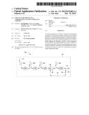
[0017] FIG. 1 illustrates an exemplary system 100 for cooling a compressed working fluid, according to one or more disclosed embodiments. The system 100 includes a compressor 102, such as a multi-stage compressor, that has a series of compression stages 104a, 104b, 104c, and 104d. In one or more embodiments, the compressor 102 is a centrifugal compressor and may form an integral part of an industrial compression system. In other embodiments, the compressor 102 may be an axial or reciprocating compressor. While only four compression stages 104a-d are illustrated, it will be appreciated that more or less compression stages may be implemented without departing from the scope of the disclosure. For instance, embodiments contemplated herein include as many as eight or ten compression stages.
[0018] The system 100 may employ a continuous cooling strategy including a series of heat exchangers 106a, 106b, 106c, and 106d fluidly coupled to and interposing succeeding compression stages 104a, 104b, 104c, and 104d, respectively. The heat exchangers 106a-d may be external heat exchangers, or they may form an integral part of the compressor 102 assembly. The heat exchangers 106a-d may any type of heat exchanging device, such as, but not limited to, direct contact heat exchangers, trim coolers, water-cooled heat exchangers, air-cooled heat exchangers, mechanical refrigeration units, combinations thereof, and the like. While only four heat exchangers 106a-d are illustrated, it will be appreciated that more or less than four may be implemented without departing from the scope of the disclosure. For instance, other embodiments contemplated herein include multiple heat exchangers interposed between each compression stage 104a-d.
[0019] The system 100 employs an evaporative cooling strategy including at least one valve 108 and at least one fogging device 110. The valve 108 may be a throttling valve such as an expansion valve. In other embodiments, the valve 108 may be an expander or a turbine configured to recover a portion of power through the expansion of the compressed working fluid. The fogging device 110 may be configured to convert the working fluid into a "fog," or atomized droplets, for injection into a target compression stage, such as the succeeding fourth compressor stage 104d. To atomize the fluid and generate the fog, a high-pressure atomizing nozzle 112 may be employed within the fogging device 110. In at least one embodiment, the atomizing nozzle 112 may be operable at pressures ranging from about 7,000 KPa to about 20,000 KPa. It will be appreciated, however, that the operable pressure ranges for the atomizing nozzle 112 may vary as a function of the gas properties. Also, while only one evaporative cooling strategy is depicted in FIG. 1, embodiments contemplated herein include having two or more evaporative cooling strategies implemented in the same compressor 102, without departing from the scope of the disclosure.
[0020] In exemplary operation, a working fluid to be compressed and/or conveyed is introduced into the system 100 and the compressor 102 via line 114. The working fluid may be a compressible gas such as, but not limited to, carbon dioxide (CO2). The first compression stage 104a compresses the incoming working fluid, thereby increasing both the pressure and the temperature of the working fluid. The suction pressure of the succeeding compression stage (i.e., the second compression stage 104b) is directly affected by its suction temperature. A cooler suction temperature will demand less power to operate the compression stage for the same mass flow to reach the same discharge pressure. Accordingly, in order to maintain a substantially iso-thermal compression process within the compressor 102, and thereby maintain or otherwise improve compressor efficiency, the first compression stage 104a conveys the working fluid to the first heat exchanger 106a where the temperature of the working fluid is decreased to at or about ambient temperature.
[0021] Once cooled in the first heat exchanger 106a, the working fluid may then be discharged to the second compression stage 104b and subsequent second heat exchanger 106b, where the compression and cooling process is generally repeated. As depicted, similar compression/cooling processes are repeated a third and a fourth time in the third compression stage 104c and third heat exchanger 106c, and the fourth compression stage 104d and fourth heat exchanger 106d, respectively. The compressor 102 then discharges a compressed working fluid via line 107 to be used, for example, in downstream applications. In one embodiment, downstream applications may include carbon dioxide sequestration and/or storage.
[0022] Lowering the working fluid temperature, especially below ambient temperature, prior to any of the compression stages 104a-d reduces the total amount of compression work required and thereby increases the efficiency of the compressor 102. For example, in order to lower the temperature of the working fluid to below ambient temperature for the fourth compression stage 104d, a portion of the working fluid discharged from the fourth heat exchanger 106d may be extracted as a recycled working fluid and directed into line 116. The extracted working fluid may be throttled through the valve 108 to bring the recycle working fluid to its saturated liquid state, resulting in a liquid or partially-liquid recycle working fluid discharged into line 118. Throttling the recycle working fluid through the valve 108 may be configured to reduce the static pressure of the recycle working fluid to at or near the suction inlet pressure of the fourth compression stage 104d.
[0023] The recycle working fluid in line 118 may then be introduced to the fogging device 110 which is fluidly coupled to a target compression stage, i.e., the compression stage that is to be evaporatively cooled. In the illustrated embodiment, the fogging device 110 is arranged to evaporatively cool the working fluid discharged from the third heat exchanger 106c before the working fluid is introduced into the inlet of the fourth compression stage 104d. Specifically, the atomizing nozzle 112 disposed within the fogging device 110 receives and atomizes the recycle working fluid derived from line 118. Atomizing the recycle working fluid facilitates its quick evaporation in the presence of the incoming working fluid from the third heat exchanger 106c, and thereby cools the incoming working fluid.
[0024] In exemplary operation, the atomizing nozzle 112 may generate a droplet size and general distribution that promotes the evaporation of the droplets before the droplets reach downstream impeller blades or other sensitive parts of the succeeding compression stage (e.g., the fourth compression stage 104d). As can be appreciated, therefore, atomization of the fluid substantially prevents machinery erosion and/or rotordynamic vibrational issues.
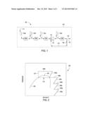
[0025] Referring to FIG. 2, depicted is a representative pressure versus enthalpy diagram 200 for the system 100 as generally described above. The diagram 200 depicts a thermodynamic phase dome 202 corresponding to a working fluid that can be used in the system 100. For instance, the phase dome 202 may be representative of CO2. The phase dome 202 is generally centered around the critical pressure point 204 of the working fluid, where the saturated liquid and saturated vapor lines meet. Above the critical point 204 and outside of the phase dome 202, the working fluid exists as a dense gas, while below the critical point 204 and inside or below the phase dome 202, the working fluid exists as a saturated liquid-vapor.
[0026] As depicted in the diagram 200, the working fluid is compressed and cooled in several stages corresponding to the system 100 described above. For example, line 206a represents compression of the working fluid in the first compression stage 104a, and line 208a represents cooling the working fluid in the first heat exchanger 106a. Likewise, lines 206b, 206c, and 206d represent compression of the working fluid in the second, third, and fourth compression stages 104b, 104c, and 104d, respectively, and lines 208b, 208c, and 208d represent cooling the working fluid in heat exchangers 106b, 106c, and 106d, respectively.
[0027] Embodiments of the system 100 described herein take advantage of the working fluid being compressed above its critical pressure, or otherwise outside the thermodynamic phase dome 202. Although an evaporative cooling strategy may be implemented at any point during the compression process, in order to maximize the regenerative cooling effect, the working fluid throttled through the valve 108 should be at or above the critical pressure point 204 of the working fluid. Since the fourth compression stage 104d (corresponding to line 206d) compresses the working fluid to either meet or exceed the critical pressure point 204, it may be characterized as an "evaporative compression stage," and evaporative cooling of the working fluid may be effectively undertaken thereafter as generally described above.
[0028] Consequently, the dashed line 210 in the diagram 200 represents the flow of the recycle working fluid via line 116 as it is throttled through the valve 108 (FIG. 1) to a saturated liquid state or saturated liquid-vapor state at or inside the thermodynamic vapor dome 202. It will be appreciated by those skilled in the art that in embodiments employing a turbine in place of the valve 108, as described above, that the dashed line 210 would proceed along an adiabatic curve. In one or more embodiments, the valve 108 may be configured to throttle the recycle working fluid to a pressure at or near the suction inlet pressure 212 of a target compression stage, such as the fourth or evaporative compression stage 104d (i.e., line 206d).
[0029] It will be appreciated that the target compression stage may also be the evaporative compression stage itself, as depicted, or any compression stage that precedes the evaporative compression stage. When the conditions of the recycle working fluid are right (e.g., at or above its critical pressure point 204), the recycle working fluid may be throttled and then subsequently atomized and injected back into the target compression stage using the atomizing nozzle 112 disposed within the fogging device 110 (FIG. 1). As the recycle working fluid is ejected from the atomizing nozzle 112, it quickly evaporates and provides regenerative cooling to the target compression stage which lowers the temperature of the working fluid below ambient temperature.
[0030] Evaporatively cooling the working fluid lowers the inlet temperature for any succeeding compression stages, and thereby reduces the total amount of work required during the compression process. Consequently, even taking into account the additional work required to re-compress the recycled working fluid and the increase in mass flowrate for succeeding compression stages, the overall power requirement demand for the system 100 is notably lowered, therefore increasing its overall efficiency.
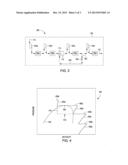
[0031] Referring now to FIG. 3, depicted is another exemplary system 300 for cooling a compressed gas, according to embodiments described herein. In some respects, the system 300 may be substantially similar to the system 100 of FIG. 1. As such, FIG. 3 may be best understood with reference to FIG. 1 where like numerals represent like components that will not be described again in detail. Similar to FIG. 1, the system 300 of FIG. 3 includes a multi-stage compressor 102 having a series of compression stages 104a-d alternatingly interposed by a corresponding series of heat exchangers 106a-d. As illustrated, however, the evaporative cooling strategy, including the valve 108 and the fogging device 110, may target the third compression stage 104c, thereby characterizing the third compression stage 104c as the evaporative compression stage. As will be described in more detail below, any compression stage that successfully compresses the working fluid to at or above the critical pressure of the working fluid may be characterized as the evaporative compression stage.
[0032] The working fluid is introduced into the system 300 via line 114 and directed to the first compression stage 104a to compress the working fluid. In order to maintain at least a substantially iso-thermal compression process, the first compression stage 104a may be configured to convey the working fluid to the first heat exchanger 106a where the temperature of the working fluid decreased to at or around ambient temperature. Once cooled, the working fluid may then be discharged from the first heat exchanger 106a, and the process may be repeated in succeeding compression stages 104b, 104c and heat exchangers 106b, 106c.
[0033] A portion of the working fluid discharged from the third heat exchanger 106c may be separated into line 302 as the recycle working fluid. The recycle working fluid is then throttled to its saturated liquid-vapor state using the valve 108 and directed to the fogging device 110 via line 304 as a liquid or partially-liquid recycle working fluid. After being atomized by the atomizing nozzle 112 disposed within the fogging device 110, the recycle working fluid evaporates in the presence of the incoming working fluid from the second heat exchanger 106b, thereby evaporatively cooling the incoming working fluid to a temperature below ambient.
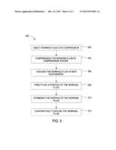
[0034] Referring to FIG. 4, depicted is a pressure versus enthalpy diagram 400 for the system 300 generally described above. The diagram 400 includes an exemplary thermodynamic phase dome 402 having a critical pressure point 404 corresponding to the working fluid used in the system 300. The working fluid is compressed and cooled in several stages corresponding to the system 300 described above. For instance, line 406a represents the compression of the working fluid in the first compression stage 104a, and line 408a represents the working fluid being cooled in the first heat exchanger 106a. Likewise, lines 406b-d represent compression of the working fluid in the second, third, and fourth compression stages 104b-d, respectively, and lines 408b-d represent cooling of the working fluid in heat exchangers 106b-d, respectively.
[0035] As illustrated, the third compression stage 104c (corresponding to line 406c in the diagram 400) is capable of compressing the working fluid to either meet or exceed the critical pressure point 404 of the working fluid. Consequently, the third compression stage 104c may be used as the evaporative compression stage in system 300, and evaporative cooling of the working fluid as described herein may be effectively undertaken at any point thereafter. Thus, the dashed line 410 in the diagram 400 represents the flow of the recycle working fluid as it is throttled through the valve 108 (FIG. 3) to a saturated liquid-vapor state inside the thermodynamic vapor dome 402. Again, it will be appreciated by those skilled in the art that in embodiments employing a turbine in place of the valve 108, that the dashed line 410 would proceed along an adiabatic curve. The recycle working fluid may be throttled to a suction inlet pressure 412 of a desired target compression stage, or the compression stage where the evaporative cooling is to take place. As illustrated in FIGS. 3 and 4, the target compression stage may be the third compression stage 104c (i.e., line 406c). Consequently, the valve 108 may be configured to throttle the recycle working fluid to at or near the suction inlet pressure 412 of the third compression stage 104c. Again, it will be appreciated that the target compression stage may be the evaporative compression stage itself or any other compression stage that precedes the evaporative compression stage.
[0036] The recycle working fluid may then be atomized and injected back into the working fluid at the third compression stage 104c via line 406c using the atomizing nozzle 112 disposed within the fogging device 110 (FIG. 3). As the recycle working fluid is ejected from the atomizing nozzle 112, it evaporatively cools the target compression stage, which allows the temperature of the working fluid to be lowered below ambient.
[0037] Referring now to FIG. 5, illustrated is a flow chart of a method 500 for cooling a working fluid. The method 500 may include injecting a working fluid into a compressor, as at 502. The working fluid may be compressed in a series of compression stages arranged in the compressor, as at 504. In at least one embodiment, one of the series of compression stages may be an evaporative compression stage that compresses the working fluid to at least its critical pressure. The working fluid may then be cooled in a series of heat exchangers fluidly coupled to the series of compression stages, as at 506. In one or more embodiments, at least one heat exchanger is interposed between each compression stage. Moreover, each heat exchanger may be configured to decrease the temperature of the working fluid discharged from a preceding compression stage to at or near ambient temperature. A portion of the working fluid may then be throttled to at least its saturated liquid-vapor state, as at 508. The portion of the working fluid may be throttled using a valve fluidly coupled to a heat exchanger following the evaporative compression stage. In other embodiments, the working fluid is throttled using an expander or turbine. The portion of the working fluid may then be atomized with a fogging device fluidly coupled to both the valve and at least one compression stage, as at 510, such as a target compression stage. The working fluid entering the at least one compression stage may then be evaporatively cooled through evaporative cooling of the throttled portion of the working fluid, as at 512.
[0038] The foregoing has outlined features of several embodiments so that those skilled in the art may better understand the present disclosure. Those skilled in the art should appreciate that they may readily use the present disclosure as a basis for designing or modifying other processes and structures for carrying out the same purposes and/or achieving the same advantages of the embodiments introduced herein. Those skilled in the art should also realize that such equivalent constructions do not depart from the spirit and scope of the present disclosure, and that they may make various changes, substitutions and alterations herein without departing from the spirit and scope of the present disclosure.
User Contributions:
Comment about this patent or add new information about this topic:
Images included with this patent application:
 |  |
 |  |
| New patent applications in this class: | |
| Date | Title |
|---|---|
| 2022-05-05 | Transport refrigeration system energy management system and method |
| 2019-05-16 | Refrigeration cycle apparatus |
| 2019-05-16 | Speed estimation apparatus for ac motor, driving apparatus for ac motor, refrigerant compressor, and refrigeration cycle apparatus |
| 2018-01-25 | Reversible heat pump with cycle enhancements |
| 2016-09-01 | Air conditioning system and control method thereof |
| Top Inventors for class "Refrigeration" | |
| Rank | Inventor's name |
|---|---|
| 1 | Michael F. Taras |
| 2 | Alexander Lifson |
| 3 | Koji Yamashita |
| 4 | Hiroyuki Morimoto |
| 5 | Patrick J. Boarman |