Patent application title: FILLER NECK FOR FILLING A FLUID SYSTEM
Inventors:
Thomas Calhoun (Southfield, MI, US)
Kip Eberle (Clarkston, MI, US)
David Forsyth (Sylvan Lake, MI, US)
Richard Obradovich (Livonia, MI, US)
IPC8 Class: AB65B304FI
USPC Class:
220 861
Class name: Receptacles container attachment or adjunct filling member
Publication date: 2013-12-12
Patent application number: 20130327767
Abstract:
A filler neck for filling a fluid system, especially for filling a
radiator assembly or an engine coolant system is provided. The filler
neck avoids breaking of joints and waiving of leak tests by a filler tube
and a filler beginning connected with the filler tube.Claims:
1. A filler neck for filling a fluid system, the filler neck comprising:
a filler tube; and a filler beginning connectable with the filler tube,
wherein the filler tube and the filler beginning are formed in one piece,
wherein the filler tube is curved and the filler beginning is directed
approximately perpendicular to a fluid system opening, wherein the filler
beginning has a larger diameter than a diameter of the filler tube,
wherein a flanged socket is fixed substantially perpendicular to the
filler beginning, and wherein the filler neck is configured for filling a
radiator assembly or an engine coolant system.
2-8. (canceled)
9. An engine coolant system comprising: a radiator having an opening lying in a first plane; a filler neck extending from the radiator opening, the filler neck comprising a curved filler tube having an outer diameter of a first size and a cylindrical filler beginning integrally formed with the filler tube at an end of the filler tube opposite the radiator, the filler beginning having an outer diameter of a second size greater than the first size, the filler tube including a flared portion at the filler beginning, the outer diameter of the filler tube increasing from the first size to the second size along the flared portion.
10. The engine coolant system according to claim 9, wherein the outer diameter of the flared portion increases continuously from the first size to the second size.
11. The engine coolant system according to claim 10, wherein the filler beginning includes an end lying in a second plane substantially perpendicular to the first plane.
12. The engine coolant system according to claim 11, wherein a radius of curvature of the filler tube is constant from the radiator opening to the filler beginning.
13. The engine coolant system according to claim 12, including a flanged socket projecting perpendicularly from the filler beginning.
14. The engine coolant system according to claim 13, wherein the filler beginning includes a projecting flange at a location spaced from the filler tube.
15. The engine coolant system according to claim 9, wherein a radius of curvature of the filler tube is constant from the radiator opening to the filler beginning.
16. A filler neck for filling a fluid system, the filler neck comprising: a filler tube portion and a filler beginning portion integrally formed with the filler tube portion, the filler tube portion having a first end connectable to an opening in the fluid system and a second end spaced from the first end, the filler neck including a flared portion between the filler tube portion second end and the filler beginning portion, the filler tube portion having a substantially constant first outer diameter, the filler beginning portion being cylindrical and having a substantially constant second outer diameter greater than the first outer diameter and the flared portion having an outer diameter that increases from the first outer diameter at the second end of the filler tube portion to the second outer diameter at the filler beginning portion, the filler tube portion being arc shaped and having a substantially constant radius of curvature from the first end to the flared portion and extending through a 90 degree arc, the filler beginning portion including a flanged socket projecting perpendicularly therefrom and an end flange at an end of the filler beginning portion opposite the filler tube portion.
Description:
BACKGROUND OF THE INVENTION
[0001] 1. Field of the Invention
[0002] The invention refers to a filler neck for filling a fluid system, especially for filling a radiator assembly or an engine coolant system.
[0003] 2. Description of the Background Art
[0004] After fabrication of radiator assemblies or engine coolant systems a cooling fluid is brought into the radiator assembly or the engine coolant system. Hence, a filler neck is necessary to fill the fluid into the radiator assembly or the engine coolant system. The filler neck is arranged in an opening of the radiator assembly or the engine coolant system. The filler neck comprises a spin welded cap or a plug to seal an end of port for cantilevered filler necks.
[0005] Spin weld of caps or plugs to seal end of port require secondary operation for leak tests. Additionally, a high risk exists of debris from spin welding process of caps. The debris can cause breaking off from joint which can lead to an engine or water pump damage.
SUMMARY OF THE INVENTION
[0006] The problem addressed in this invention is to provide a filler neck, which avoids breaking of joints and waiving of leak tests.
[0007] In an embodiment, a filler tube and a filler beginning connected with the filler tube creates the filler neck. Because of abstinence of spin weld of caps or plug to seal end of port radiator assemblies and engine coolant systems are protected for damages. The coolant flow is improved and the pressure drop during the filling cycle is reduced. Consequently, customer costs are reduced.
[0008] In addition, the filler tube and the filler beginning are formed in one piece. A leak test of the filler neck can consequently be omitted. Hence, the fill speed is improved.
[0009] Furthermore, the filler neck comprises rotary device. Hence, fixing of the filler neck to the fluid system can be achieved by very simple handling.
[0010] In another aspect of the invention, the filler tube can be curved wherein the filler beginning is directed approximately perpendicular to a fluid system opening. The new design of filler neck allows an easy method for filling the fluid into the fluid system like the radiator or the engine coolant system, because the fluid flow is improved.
[0011] Moreover, the filler beginning has a larger diameter compared to the diameter of the filler tube. The filler beginning can contain a lot of fluid wherein the filling cycle is accelerated because an uninterrupted fluid supply to the fluid system is ensured.
[0012] In addition, a flanged socket is fixed to the filler beginning. This flanged socket serves pressure compensation between the environment and the inner fluid system.
[0013] Furthermore, the flanged socket is fixed perpendicularly to the filler beginning. Consequently, the pressure drop is reduced during the filling cycle.
[0014] Further scope of applicability of the present invention will become apparent from the detailed description given hereinafter. However, it should be understood that the detailed description and specific examples, while indicating preferred embodiments of the invention, are given by way of illustration only, since various changes and modifications within the spirit and scope of the invention will become apparent to those skilled in the art from this detailed description.
BRIEF DESCRIPTION OF THE DRAWINGS
[0015] The present invention will become more fully understood from the detailed description given hereinbelow and the accompanying drawing which is given by way of illustration only, and thus, is not limitive of the present invention, and wherein the FIGURE illustrates an example embodiment, showing a cross-sectional view of an adjustment fitting with sealing of the eccentric receiving space.
DETAILED DESCRIPTION
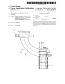
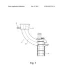
[0016] The figure shows a first embodiment of the filler neck 1 according to the invention. Such a filler neck 1 is used by filling a fluid system with fluid. Such fluid systems are especially radiator assemblies or engine coolant systems, which are filled with a coolant.
[0017] The filler neck 1 includes a filler tube 2 and a filler beginning 3. The filler tube 2 is arranged on the fluid system 4 wherein the filler tube 2 is curved. Hence, the filler beginning 3, which is designed at the filler tube 2 opponent to the fluid system 4, is directed perpendicularly to an opening of the fluid system 4 not depicted in addition. Laterally, a flanged socket 5 extends to the filler beginning 3. The diameter of the filler beginning 3 is larger as the diameter of the filler tube 2.
[0018] The whole filler neck 1 comprises the filler tube 2, the filler beginning 3 and the flanged socket 5 and is fabricated as one piece. Advantageously, the filler neck is formed of plastic material. The filler neck 1 is fixed at the fluid system 4 by a rotary device.
[0019] The described embodiment allows a low cost assembling of the filler neck, because leak tests are not necessary because no joints are between the filler tube 2 and the filler beginning 3. Contaminations due to assembling processes of the filler neck 1 are omitted. The design of filler neck 1 improves the coolant flow during filling cycle and reduce pressure drop during filling cycle.
[0020] The invention being thus described, it will be obvious that the same may be varied in many ways. Such variations are not to be regarded as a departure from the spirit and scope of the invention, and all such modifications as would be obvious to one skilled in the art are to be included within the scope of the following claims.
User Contributions:
Comment about this patent or add new information about this topic:
Images included with this patent application:
 |  |
| Similar patent applications: | |
| Date | Title |
|---|---|
| 2013-01-03 | Filler neck for a fuel tank |
| 2014-05-08 | Retractable handle for electronic devices and protective cases and method of use |
| 2013-05-02 | Apparatus for sublimating solid state precursors |
| 2014-05-08 | Internal support structure and food container system |
| 2014-05-08 | Receptacle of gel card type equipped with a lid comprising a precut |
| New patent applications in this class: | |
| Date | Title |
|---|---|
| 2016-06-02 | Component for filling a liquid into a liquid container |
| 2016-05-26 | Trash receptacle attachment |
| 2016-05-12 | Check valve and receptacle structure |
| 2016-03-24 | Garbage can caddy |
| 2015-12-31 | Fuel tank ground assembly |
| New patent applications from these inventors: | |
| Date | Title |
|---|---|
| 2008-10-30 | Heater core assembly |
| 2008-09-18 | Cooling system for a motor vehicle |
| 2008-08-28 | Cooling system for a motor vehicle |
| Top Inventors for class "Receptacles" | |
| Rank | Inventor's name |
|---|---|
| 1 | Daniel Lee Bizzell |
| 2 | Frank Yang |
| 3 | Terry Vovan |
| 4 | William P. Apps |
| 5 | Lowell L. Wood, Jr. |