Patent application title: Boxing machine
Inventors:
Dean Derek Scully (Dublin, IE)
Daniel Sheridan (Dublin, IE)
IPC8 Class: AA63B6922FI
USPC Class:
482 87
Class name: Striking multidirectionally movable bag or pad specifically supported
Publication date: 2013-09-05
Patent application number: 20130231223
Abstract:
This is a wall mounted machine which has one moving part and can be
adjusted to the height of the person using it. It is a machine which can
replicate any form of combat which uses punches, elbows and kicks. The
machine is mounted to a wall by way of the frame. The rotating bar has
two targets at each end. The targets are double sided and are covered
with padding. This means the machine has four targets front and back of
each pad.Claims:
1. A boxing machine for training purposes comprising of; a wall mounted
frame (5); a main support bar (9); secondary support bars (3+8) to
reinforce stability to the main support bar; a chamber (4) attached to
the main bar used to hold the rod; an internal insert positioned inside
the chamber to reduce noise and vibration; a threaded/non-threaded rod
(2) in the chamber (4); a rotating bar (1) with two targets positioned at
either end; this rotating bar having the ability to move up/down the
threaded rod or remain at a designated position with a non-threaded rod;
lock nuts (6) used to stop rod (2) rotating in the chamber (4).
2. A boxing machine claimed in claim 1; the targets can be double sided giving four possible targets; the targets can be covered with a padding of any suitable material in any design and shape.
3. A boxing machine as herein described with reference to the accompanying drawings.
Description:
FIELD OF INVENTION
[0001] The machine replicates combat training using striking pads.
DESCRIPTION
[0002] The machine is mounted to a wall by way of a frame (5). The frame (5) is a cross shape design with infusions at the end of each axis. The rotating bar (1) screws onto the rod (2) which is held in place by the chamber (4). The chamber (4) contains an internal insert made of plastic (not shown in drawings). The internal insert is to reduce noise and vibration. The rod (2) is secured by the lock nuts (6) top and bottom of the chamber (4) to stop it from rotating. The rod (2) can be threaded or unthreaded depending on the requirements. The chamber (4) is attached to the frame (5) by way of the main support bar (9). The main support bar (9) has three secondary support bars (3+8). The bars which give support are situated on the left (3) and on the right (3) and directly below (8) the main bar (9).The secondary support bars (3+8) give support to the main bar (9) when the machine is being struck. It stops the main bar (9) from moving left and right when hit with force.
[0003] The rotating bar (1) has two round targets at each end. The targets are double sided and are covered with padding this means the machine has four targets front and back of each pad, meaning you can work on multiple combinations when striking it. When using a threaded rod (2) the rotating bar (1) rotates up, down, left and right meaning the targets are always moving just like an opponent would in a fight. This is excellent for your timing, hand eye coordination and also footwork. It helps footwork because the rotating bar rotates 360 degrees meaning you can work on angles and strike it while moving left and right. The rotating bar can rotate extremely quickly. It can move as fast as you can hit it. This will help with speed and endurance. When using a threaded rod (2) the rotating bar (1) rotates to the top and bottom of the rod (2) meaning it can be adjusted to a height that suits the person using it. When using a non-threaded rod (2) the rotating bar will only move in a 360 degree motion and will not move up or down.
DRAWINGS
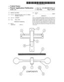
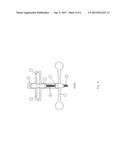
[0004] FIG. 1 is a front view of the machine with a threaded rod (2) rotating bar (2) and lock nuts (6) shown not connected to the machine.
[0005] FIG. 2 is a front view of the machine with every part ready to put together.
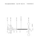
[0006] FIG. 3 is a new view looking directly down on the machine you can see the secondary support bars (3) connected to the main support bar (9) leading to the chamber (4) and the rotating bar (1).
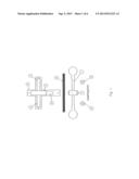
[0007] FIG. 4 is a front view of the machine with every part in place and ready to be used. The rotating bar (1) is on the threaded rod (2). The threaded rod (2) is connected to the chamber (4) the lock nuts (6) are secured in place top and bottom of the chamber (4).
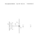
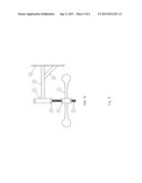
[0008] FIG. 5 is a side view of the machine you can see the support bar (8) underneath the main frame (5) to the main support bar (9) the main bar going from the frame to the chamber (4) the threaded rod (2) screwed into the chamber (4) and held in place by the lock nuts (6) the rotating bar threaded onto the threaded rod (2).
[0009] FIG. 6 is a view of the machine at every angle, all parts connected and disconnected.
User Contributions:
Comment about this patent or add new information about this topic:
Images included with this patent application:
 |  |
 |  |
 |  |
 |  |
| Similar patent applications: | |
| Date | Title |
|---|---|
| 2014-10-02 | Core exercising machine |
| New patent applications in this class: | |
| Date | Title |
|---|---|
| 2018-01-25 | Adjustable swivel mount device for heavy punching bag |
| 2017-08-17 | Combat training device |
| 2016-06-23 | Athletic training apparatus |
| 2016-01-28 | Martial arts training bag |
| 2015-12-31 | Rotary training equipment |
| Top Inventors for class "Exercise devices" | |
| Rank | Inventor's name |
|---|---|
| 1 | William T. Dalebout |
| 2 | Scott R. Watterson |
| 3 | Raymond Giannelli |
| 4 | Leao Wang |
| 5 | Bruce Hockridge |