Patent application title: TRAY FOR A FOOD PRODUCT
Inventors:
Samir R. Parikh (Brampton, CA)
Sajith Chenat (Brampton, CA)
Assignees:
PAR-PAK LTD.
IPC8 Class: AB65D2102FI
USPC Class:
206507
Class name: Structural features for vertical stacking, i.e., similar receptacles having specified means for nesting instead of stacking by selective orientation of superposed receptacles
Publication date: 2013-08-08
Patent application number: 20130199959
Abstract:
A tray for a food product is thin-walled, unitary, and plastic. The tray
comprises a central portion. The central portion comprises a plurality of
downwardly extending recesses for receiving at least one of the food
products, and a plurality of upwardly extending posts interspersed
amongst the recesses. A first set of the posts is positioned on a first
side of a horizontal axis of the tray, and a second set of the posts is
positioned on a second side of the horizontal axis. The first set of
posts and the second set of posts are positioned asymmetrically on either
side of the horizontal axis. Each post comprises a plurality of
reinforcing ribs extending lengthwise therealong. The reinforcing ribs
are integral to the posts. The tray further comprises an outer wall
portion extending about the central portion. A plurality of webs extend
between the outer wall portion and the central portion.Claims:
1. A thin-walled unitary plastic tray for a plurality of food products,
comprising: a) a central portion comprising: i) a plurality of downwardly
extending recesses for receiving at least one of the food products; ii) a
plurality of upwardly extending posts interspersed amongst the recesses,
a first set of the posts positioned on a first side of a horizontal axis
of the tray, and a second set of the posts positioned on a second side of
the horizontal axis, the first set of posts and the second set of posts
positioned asymmetrically on either side of the horizontal axis; and iii)
each post comprising a plurality of reinforcing ribs extending lengthwise
therealong, the reinforcing ribs integral to the posts; b) an outer wall
portion extending generally upright about the central portion; and c) a
plurality of webs extending between an inner surface of the outer wall
portion and the central portion.
2. The tray of claim 1, wherein: a) the posts are shaped to align with and nest within posts of a second, like tray when the tray is in a first orientation relative to the second tray, to allow vertically collapsed nesting of the tray with the second tray; b) the posts misalign with the posts of the second tray when the tray is in a second orientation, to prevent nesting of the tray with the second tray and allow vertically expanded stacking of the tray with the second tray; and c) to move between the first orientation and the second orientation, the tray is rotated about a vertical axis relative to the second tray.
3. The tray of claim 2, wherein the tray is rotated about the vertical axis by an angle of about 180 degrees.
4. The tray of claim 2, further comprising a plurality of abutment members interspersed amongst the posts and recesses.
5. The tray of claim 4, wherein: a) a first set of the abutment members and the second set of posts are positioned symmetrically on either side of the horizontal axis; and b) a second set of the abutment members and the first set of posts are positioned symmetrically on either side of the horizontal axis.
6. The tray of claim 5, wherein the abutment members comprise a downwardly extending depression having a bottom abutment surface.
7. The tray of claim 6, wherein the bottom abutment surfaces each comprise a locating dimple for receiving an upper portion of a respective one of the posts of the second tray when in the second orientation.
8. The tray of claim 5, wherein when the tray is in the second orientation, the first set of posts abuts the second set of abutment members of the other tray, and the second set of posts abuts the first set of abutment members of the other tray.
9. The tray of claim 4, wherein the webs extend between the outer wall portion and the abutment members.
10. The tray of claim 1, wherein the first set of posts includes a first number of posts, and the second set of posts includes a second number of posts, and the first number is different from the second number.
11. The tray of claim 1, wherein the tray comprises five webs extending between the outer wall portion and the central portion.
12. The tray of claim 1, wherein the reinforcing ribs extend from a bottom portion of the posts to a top portion of the posts.
Description:
FIELD
[0001] The disclosure relates to trays for storing and/or transporting food products, such as muffins.
BACKGROUND
[0002] U.S. patent application publication No. U.S.20110132796A1 (Epstein) purports to disclose a multi-compartment food tray that includes at least a first compartment and a second compartment formed from a paperboard material. Each compartment includes a compartment lip, and a carrier constructed from a paperboard material and including openings receiving the first and second compartments. Each compartment lip may be mechanically coupled to the carrier to create an interface. The interface may remain coupled during food reconstitution, and may include at least one surface having a coating. The first compartment may have a different volume than the second compartment.
SUMMARY
[0003] The following summary is intended to introduce the reader to various aspects of the applicant's teaching, but not to define any invention.
[0004] According to one broad aspect, a tray for a plurality food products is disclosed. The tray is thin-walled, unitary, and plastic. The tray comprises a central portion. The central portion comprises a plurality of downwardly extending recesses for receiving at least one of the food products, and a plurality of upwardly extending posts interspersed amongst the recesses. A first set of the posts is positioned on a first side of a horizontal axis of the tray, and a second set of the posts is positioned on a second side of the horizontal axis. The first set of posts and the second set of posts are positioned asymmetrically on either side of the horizontal axis. Each post comprises a plurality of reinforcing ribs extending lengthwise therealong. The reinforcing ribs are integral to the posts. The tray further comprises an outer wall portion extending about the central portion. A plurality of webs extend between the outer wall portion and the central portion.
[0005] The posts may align with and nest within posts of another tray when the tray is in a first orientation, to allow nesting of the tray with the other tray. The posts may mis-align with the posts of the other tray with the tray is in a second orientation, to prevent nesting of the tray with the other tray and allow stacking of the tray with the other tray. To move the tray between the first orientation and the second orientation, the tray may be rotated about a vertical axis. The tray may be rotated about the vertical axis by an angle of about 180 degrees.
[0006] The tray may further comprise a plurality of abutment members interspersed amongst the posts and recesses. The tray may comprise a first set of abutment members. The first set of abutment members and the second set of posts may be positioned symmetrically on either side of the horizontal axis. The tray may further comprise a second set of abutment members. The first set of abutment members and the first set of posts may be positioned symmetrically on either side of the horizontal axis.
[0007] The abutment members may comprise a downwardly extending depression having a bottom abutment surface. The bottom abutment surfaces may each comprise a locating dimple for receiving one of the posts of another tray. When the tray is in the second orientation, the first set of posts may abut the second set of abutment members of the other tray, and the second set of posts may abut the first set of abutment members of the other tray.
[0008] The webs may extend between the outer wall portion and the abutment members.
[0009] The first set of posts may include a first number of posts, and the second set of posts may include a second number of posts. The first number may be different from the second number.
[0010] The tray may comprise five webs extending between the outer wall portion and the central portion.
[0011] The reinforcing ribs may extend from a bottom portion of the posts to a top portion of the posts.
BRIEF DESCRIPTION OF THE DRAWINGS
[0012] The drawings included herewith are for illustrating various examples of articles, methods, and apparatuses of the present specification and are not intended to limit the scope of what is taught in any way. In the drawings:
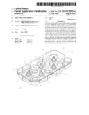
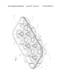
[0013] FIG. 1 is a perspective illustration of a tray;
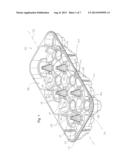
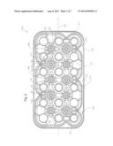
[0014] FIG. 2 is a top plan view of the tray of FIG. 1;
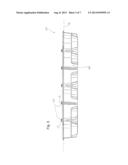
[0015] FIG. 3 is a side plan view of the tray of FIG. 1;
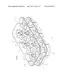
[0016] FIG. 4 is a perspective illustration of the tray of FIG. 1, nested within another tray;
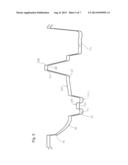
[0017] FIG. 5 is a cross-section taken along line 5-5 in FIG. 4;
[0018] FIG. 6 is a perspective illustration of the tray of FIG. 1, with another tray stacked thereon; and
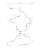
[0019] FIG. 7 is a cross-section taken along line 7-7 in FIG. 6.
DETAILED DESCRIPTION
[0020] Various apparatuses or processes will be described below to provide an example of an embodiment of each claimed invention. No embodiment described below limits any claimed invention and any claimed invention may cover processes or apparatuses that differ from those described below. The claimed inventions are not limited to apparatuses or processes having all of the features of any one apparatus or process described below or to features common to multiple or all of the apparatuses described below. It is possible that an apparatus or process described below is not an embodiment of any exclusive right granted by issuance of this patent application. Any invention disclosed in an apparatus or process described below and for which an exclusive right is not granted by issuance of this patent application may be the subject matter of another protective instrument, for example, a continuing patent application, and the applicants, inventors or owners do not intend to abandon, disclaim or dedicate to the public any such invention by its disclosure in this document.
[0021] Referring to FIGS. 1 to 3, an exemplary tray 100 is shown. The tray 100 may be used to store and/or transport a food product. In the example shown, the tray 100 is configured to store and/or transport a muffin, or similarly shaped food product. In alternate examples, a tray may be configured to store and/or transport another type of food product.
[0022] In the example shown, the tray 100 is fabricated from a plastic, such as polyethylene terephthalate (PETE), and is thin-walled and unitary. For example, the tray 100 may be thermoformed from a sheet of plastic. In alternate examples, a tray may be formed from another material.
[0023] Referring still to FIGS. 1 to 3, the tray 100 includes a central portion 102, which receives the food products, and an outer wall portion 104 extending about the central portion 102.
[0024] Referring still to FIGS. 1 to 3, the central portion 102 includes a plurality of downwardly extending recesses 106. Each recess 106 may receive at least one of the food products. In the example shown, the central portion 102 includes eighteen recesses 106 that are arranged in a three by six grid, and each recess 106 is configured to receive one muffin. Specifically, each recess is generally inverted frustoconical in shape. In alternate examples, a central portion may include an alternate number of recesses, such as twelve recesses, and the recesses may be arranged in an alternate fashion, such as a three by four grid. Further, the recesses may be of an alternate shape, such as cylindrical or cubic.
[0025] Referring still to FIGS. 1 and 2, the central portion 102 further includes a plurality of upwardly extending posts 108 interspersed amongst the recesses 106 (only two of the posts are labeled in the Figures). The posts 108 serve to provide structural rigidity to the central portion 102, and also allow the tray 100 to selectively stack or nest with other trays, as will be explained further below with reference to FIGS. 4 to 7.
[0026] Referring still to Figures and 2, in the example shown, the posts 108 are generally frustoconical, and have a top portion 110, a bottom portion 112, and a length extending therebetween. The posts 108 extend generally vertically upwardly. In alternate examples, posts may be another shape, such as cylindrical, or cubic.
[0027] Referring still to FIGS. 1 to 3, the posts 108 further include a plurality of reinforcing ribs 114, which are integral to the posts 108. The reinforcing ribs 114 extend generally lengthwise along the posts 108.
[0028] In the example shown, each post includes eight reinforcing ribs 114, which extend in a generally linear fashion from the top portion 110 to the bottom portion 112 of each post 108.
[0029] As mentioned above, the posts 108 allow the tray 100 to selectively stack or nest with other trays. Referring still to FIGS. 1 to 3, the tray 100 extends along a horizontal axis 116. A first set 118 of the posts 108 is positioned on a first side of the horizontal axis 116, and a second set 120 of the posts 108 is positioned on a second side of the horizontal axis 116. The first set 118 of posts 108 and the second set 120 of posts 108 are positioned asymmetrically on either side of the horizontal axis 116. That is, the first set 118 of posts 108 and the second set 120 of posts 108 are not positioned in a mirror image fashion on either side of the horizontal axis 116. In the example illustrated, the first set 118 has three posts 108, and the second set 120 has to posts 108.
[0030] Referring now to FIGS. 4 and 5, the tray 100 is shown in a first orientation with respect to another second, upper tray 200. The second tray 200 is essentially identical to the tray 100, and like features in tray 200 are identified by like reference characters, incremented by 100. In this orientation, the posts 108 of the tray 100 align with and nest within the hollow interiors of the posts 208 of the other tray 200. Specifically, the first set 118 of posts 108 of the tray 100 aligns with and nests within the first set 218 of posts 208 of the other tray 200, and the second set 120 of posts 108 of the tray 100 aligns with and nests within the second set 220 of posts 208 of the other tray 200, to allow nesting of the tray 100 with the other tray 200 in a vertically compact or compressed manner. Such nesting may be useful, for example, in storing and/or transporting empty trays.
[0031] Referring now to FIGS. 6 and 7, the tray 100 is shown in a second orientation with respect to the second tray 200. In this orientation, the tray 100 has been rotated by 180 degrees about a vertical axis 122 with respect to the other tray 200, so that the horizontal axis 116 of the tray 100 has been rotated by 180 degrees. In this orientation, the posts 108 of the tray 100 mis-align with the posts 208 of the other tray 200. Specifically, the first set 118 of posts 108 of the tray 100 aligns with neither the first set 218 of posts 208 nor the second set 220 of posts 108 of the other tray 200, and the second set 120 of posts 108 of the tray 100 aligns with neither the second set 220 of posts 208 nor the first set 218 of posts 208 of the other tray 200. In this orientation, nesting of the tray 100 with the other tray 200 is prevented, and stacking of the tray 100 with the other tray 200 is allowed in a vertically expanded manner. Such stacking may be useful, for example, in storing and/or transporting full trays. The bottom surface of the upper tray 200 can remain spaced apart from muffins in the lower tray 100 (FIG. 7), when the trays are stacked.
[0032] In the example shown, the first set 118 of posts 108 includes a first number of posts, and the second set 120 of posts 108 includes a second number of posts that is different from the first number. Specifically, the first set 118 of posts 108 includes three posts 108, and the second set 120 of posts 108 includes two posts 108. The posts 108 of the first set 118 are arranged generally in a first row, and are generally evenly spaced apart along the length of the tray 100. The posts 108 of the second set 120 are spaced apart along the length of the tray 100 and aligned along a second row, and as mentioned above, are not positioned in a mirror image fashion with any of the posts 108 of the first set 118.
[0033] In alternate examples, posts may be positioned in another manner. For example, the first number of posts and the second number of posts may be equal.
[0034] Referring back to FIGS. 1 to 3, in the example shown, the tray 100 further includes a plurality of abutment members 124 interspersed amongst the posts 108 and recesses 106 (only two of the abutment members are labeled in the Figures). Specifically, the tray includes a first set 126 of abutment members 124 interspersed amongst the first set 118 of posts 108, and a second set 128 of abutment members 124 interspersed amongst the second set 120 of posts 108. The first set 126 of abutment members 124 and the second set 128 of posts 108 are positioned symmetrically on either side of the horizontal axis 116. The second set 128 of abutment members 124 and the first set 118 of posts 108 are positioned symmetrically on either side of the horizontal axis 116. That is, the first set 126 of abutment members 124 and the second set 128 of posts 108 are positioned in a mirror image fashion on either side of the horizontal axis 116, and the second set 128 of abutment members 124 and the first set 118 of posts 108 are positioned in a mirror image fashion on either side of the horizontal axis 116.
[0035] In the example shown, the abutment members 124 are downwardly extending depressions, which have a bottom abutment surface 132 (shown in FIGS. 5 and 7). The bottom abutment surface includes a locating dimple 134 (shown in FIGS. 5 and 7).
[0036] Referring back to FIGS. 6 and 7, when the tray 100 is in the second orientation, the posts 108 abut the abutment members 224 of the other tray 200, to support the other tray 200 and prevent lateral sliding of the other tray 200. Specifically, the first set 118 of posts 108 abuts the second set 228 of abutment members 224 of the other tray 200, and the second set 120 of posts 108 abuts the first set 226 of abutment members 224 of the other tray 200. Further, the top portions 110 of the posts 108 are received in the locating dimples 234 of the other tray 200, to prevent lateral shifting of the trays when the trays are stacked.
[0037] Referring back to FIGS. 1 to 3, the tray further includes a plurality of webs 136 extending between the outer wall portion 104 and the central portion 102. The webs 136 may provide structural support to the tray 100. In the example shown, the tray 100 includes five webs 136, and the webs 136 each extend between an inner surface of the outer wall portion 104 and one of the abutment members 124.
[0038] In alternate examples, a tray may include another number of webs. Further, the webs may be positioned in another manner. For example, the webs may extend between the outer wall portion and the posts.
[0039] Referring to FIGS. 1 and 2, in the example shown, the webs 136 include a pair of opposed side walls 138, 140, and a top wall 142 (labeled only on one of the webs). The top wall 142 is sloped generally downwardly.
[0040] In alternate examples, webs may be of another shape and/or configuration. For example, the webs may include only a single generally vertically extending wall.
[0041] While the above description provides examples of one or more processes or apparatuses, it will be appreciated that other processes or apparatuses may be within the scope of the accompanying claims.
User Contributions:
Comment about this patent or add new information about this topic:
| People who visited this patent also read: | |
| Patent application number | Title |
|---|---|
| 20140335558 | Method for the Characterization of Microorganisms on Solid or Semi-Solid Media |
| 20140335557 | APPARATUS FOR COUNTING VIABLE PARTICLES IN LIQUID IN REAL TIME, DIALYSIS FLUID MONITORING SYSTEM AND PURIFIED WATER MONITORING SYSTEM USING THE APPARATUS, AND METHOD OF COUNTING VIABLE PARTICLES IN LIQUID IN REAL TIME |
| 20140335556 | MASS SPECTROMETRIC DETERMINATION OF MICROBIAL RESISTANCES |
| 20140335555 | AUTOMATED VITRIFICATION DEVICE |
| 20140335554 | APPARATUS AND METHODS FOR ALIQUOTTING FROZEN SAMPLES |
Images included with this patent application:
 |  |
 |  |
 |  |
 |  |
| Similar patent applications: | |
| Date | Title |
|---|---|
| 2014-06-05 | Agriculturally active product |
| 2014-06-26 | Tray for carton packages |
| 2014-06-19 | Container for storing a drug such as insulin |
| New patent applications in this class: | |
| Date | Title |
|---|---|
| 2016-03-17 | Adjustable base device, system and method of use |
| 2014-10-30 | Reinforced nestable container |
| 2014-09-11 | Helically stackable container |
| 2014-05-08 | Front-to-front low position tray |
| 2012-09-27 | Bakery tray |
| New patent applications from these inventors: | |
| Date | Title |
|---|---|
| 2017-06-22 | Container for food items |
| 2015-06-25 | Tamper evident container with frangible hinge |
| 2013-01-03 | Container for food items |
| 2010-04-29 | Tamper evident container with frangible hinge |
| Top Inventors for class "Special receptacle or package" | |
| Rank | Inventor's name |
|---|---|
| 1 | Donald E. Weder |
| 2 | Brett R. Glass |
| 3 | Daniel Lee Bizzell |
| 4 | Andrea Biondi |
| 5 | Nicole E. Glass |