Patent application title: SAFETY GAUGE TO PREVENT SLING USERS FROM EXCEEDING A SAFE WORKING LOAD OF A SLING
Inventors:
Mark Conrad Erickson (Ellabell, GA, US)
IPC8 Class: AG01D700FI
USPC Class:
116201
Class name: Signals and indicators indicators methods
Publication date: 2013-08-01
Patent application number: 20130192512
Abstract:
A safety gauge prevents sling users from exceeding the safe working load
of a sling. Unlike conventional devices, the safety gauge described
herein has no interference from internal yarns and can be preset to a
prescribed load. A strand of yarn (indicator yarn) can be disposed
between inner and outer jackets of the sling, in a choke configuration,
and attached to an indicator. The outer jacket is then closed in the
traditional manner and a window tag in the outer layer is strategically
placed over the indicator to permit a user to view the indicator during
use of the sling. When pressure is applied, the indicator yarn begins to
move in direct relation to the load being applied, causing the indicator
to move in the window tag. At a predetermined point, a red color shows,
alerting the user that they are in danger of an overload.Claims:
1. A safety gauge for a sling, comprising: a tag yarn disposed between an
outer layer and an inner layer of the sling; a ring formed in a first end
of the tag yarn, a second end of the tag yarn extending through the ring
and attached to an indicator; and an outer cover tag window disposed in
the outer layer, wherein the indicator is viewable through the outer
cover tag window such that a white color region of the indicator is
viewable when no force is applied to the sling and a red color region of
the indicator is viewable as the force applied to the sling approaches a
working load limit of the sling.
2. The safety gauge of claim 1, wherein the tag yarn is formed from a single strand of the material used for internal yarn of the sling.
3. The safety gauge of claim 1, wherein the indicator is a polymeric indicator tag.
4. The safety gauge of claim 1, further comprising an outer cover tag comprising an outer cover tag print region and the outer cover tag window.
5. A safety gauge for a sling, comprising: an inner layer of the sling; internal yarn disposed within the inner layer of the sling; a tag yarn disposed between an outer layer of the sling and the inner layer, the tag yarn formed from at least one strand of the internal yarn; a ring formed in a first end of the tag yarn, a second end of the tag yarn extending through the ring and attached to an indicator; and an outer cover tag window disposed in the outer layer, wherein the indicator is viewable through the outer cover tag window such that a white color region of the indicator is viewable when no force is applied to the sling and a red color region of the indicator is viewable as the force applied to the sling approaches a working load limit of the sling.
6. The safety gauge of claim 5, wherein the indicator is a polymeric indicator tag.
7. The safety gauge of claim 5, further comprising an outer cover tag comprising an outer cover tag print region and the outer cover tag window.
8. A method for preventing a user from exceeding a working load limit of a sling, the method comprising: disposing a tag yarn between an inner layer and an outer layer of a sling, a first end of the tag yarn formed in a ring and the second end of the tag yarn passing through the ring and attached to an indicator viewable through a window formed in the outer layer; and discontinuing use of the sling when a red color region of the indicator is visible in the window.
9. The method of claim 8, wherein the tag yarn is formed from a single strand of the material used for internal yarn of the sling.
10. The method of claim 8, further comprising providing sling instructions on an outer cover tag print region of the sling.
Description:
CROSS-REFERENCE TO RELATED APPLICATION
[0001] This application claims the benefit of priority of U.S. provisional application number 61/591,586, filed Jan. 27, 2012, the contents of which are herein incorporated by reference.
BACKGROUND OF THE INVENTION
[0002] The present invention relates to safety devices and, more particularly, to a safety gauge to prevent sling users from exceeding a safe working load of a sling.
[0003] Often, sling users do not know the exact load weight and are at risk of overload. Without having an indicator as to if they are over the safe working load of the sling, overload can occur, which can lead to injury or death.
[0004] Conventional load weight devices have interference from internal yarns, causing unreliable results. Some conventional devices can be easily tampered with, making for unreliable output.
[0005] As can be seen, there is a need for an improved safety gauge to prevent sling users from exceeding a safe working load of a sling.
SUMMARY OF THE INVENTION
[0006] In one aspect of the present invention, a safety gauge for a sling, comprises a tag yarn disposed between an outer layer and an inner layer of the sling; a ring formed in a first end of the tag yarn, a second end of the tag yarn extending through the ring and attached to an indicator; and an outer cover tag window disposed in the outer layer, wherein the indicator is viewable through the outer cover tag window such that a white color region of the indicator is viewable when no force is applied to the sling and a red color region of the indicator is viewable as the force applied to the sling approaches a working load limit of the sling.
[0007] In another aspect of the present invention, a safety gauge for a sling, comprises an inner layer of the sling; internal yarn disposed within the inner layer of the sling; a tag yarn disposed between an outer layer of the sling and the inner layer, the tag yarn formed from at least one strand of the internal yarn; a ring formed in a first end of the tag yarn, a second end of the tag yarn extending through the ring and attached to an indicator; and an outer cover tag window disposed in the outer layer, wherein the indicator is viewable through the outer cover tag window such that a white color region of the indicator is viewable when no force is applied to the sling and a red color region of the indicator is viewable as the force applied to the sling approaches a working load limit of the sling.
[0008] In a further aspect of the present invention, a method for preventing a user from exceeding a working load limit of a sling comprises disposing a tag yarn between an inner layer and an outer layer of a sling, a first end of the tag yarn formed in a ring and the second end of the tag yarn passing through the ring and attached to an indicator viewable through a window formed in the outer layer; and discontinuing use of the sling when a red color region of the indicator is visible in the window.
[0009] These and other features, aspects and advantages of the present invention will become better understood with reference to the following drawings, description and claims.
BRIEF DESCRIPTION OF THE DRAWINGS
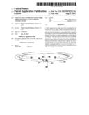
[0010] FIG. 1 is a perspective view of a sling having a safety gauge according to an exemplary embodiment of the present invention;
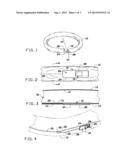
[0011] FIG. 2 is a detailed front view of the safety gauge of FIG. 1;
[0012] FIG. 3 is a cross-sectional view taken along line 3-3 of FIG. 1;
[0013] FIG. 4 is a partially cut-away perspective view of the sling with the safety gauge of FIG. 1, in a relaxed state;
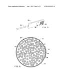
[0014] FIG. 5 is a perspective view of a polymer color indicator tag of the safety gauge of FIG. 1;
[0015] FIG. 6 is a cross sectional view taken along line 6-6 of FIG. 2;
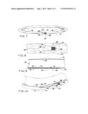
[0016] FIG. 7 is a perspective view of the sling of FIG. 1, shown in a force-applied state;
[0017] FIG. 8 is a detailed front view of the safety gauge of FIG. 7, shown in a force-applied state;
[0018] FIG. 9 is a cross-sectional view taken along line 9-9 of FIG. 7; and
[0019] FIG. 10 is a partially cut-away perspective view of the sling with the safety gauge of FIG. 7, in a force-applied state.
DETAILED DESCRIPTION OF THE INVENTION
[0020] The following detailed description is of the best currently contemplated modes of carrying out exemplary embodiments of the invention. The description is not to be taken in a limiting sense, but is made merely for the purpose of illustrating the general principles of the invention, since the scope of the invention is best defined by the appended claims.
[0021] Broadly, an embodiment of the present invention provides a safety gauge that can prevent sling users from exceeding the safe working load of a sling. Unlike conventional devices, the safety gauge described herein has no interference from internal yarns and can be preset to a prescribed load. A strand of yarn (indicator yarn) can be disposed between inner and outer jackets of the sling, in a choke configuration, and attached to an indicator. The outer jacket is then closed in the traditional manner and a window tag in the outer layer is strategically placed over the indicator to permit a user to view the indicator during use of the sling. When pressure is applied, the indicator yarn begins to move in direct relation to the load being applied, causing the indicator to move in the window tag. At a predetermined point, a red color shows, alerting the user that they are in danger of an overload.
[0022] Referring now to FIGS. 1 through 10, a sling can have an inner cover 12 and an outer cover 10 encasing internal yarn 14 disposed within an internal yarn cavity 34. An indicator 16 can be disposed to be viewable through an outer cover tag window 28 formed in an outer cover tag 24 of the outer cover 10. An outer cover tag information print region 26 can be disposed on the outer cover tag 24. This region 26 can provide information about the sling, its load limits, and the like.
[0023] The indicator 16 can be, for example, a polymeric color indicator tag having a white color region 18 and a red color region 20 viewable through the outer cover tag window 28.
[0024] A tag yarn 22 can extend about the sling, between the inner cover 12 and the outer cover 10. The tag yarn 22 can be, for example, made of the same material as the internal yarn 14. The tag yarn 22 can pass from a first end formed in a ring 30, around the sling, back through the ring 30 to turn the tag yarn 22 back about 180 degrees to attach to the indicator 16. The tag yarn 22 can be, for example, a polyester or a high performance aramid fiber.
[0025] When a force is applied (indicated, for example, by arrows 32 in FIG. 7), the indicator 16 can show more of the red color region 20, indicating that the user is approaching a load limit of the sling.
[0026] The indicator 16 is disposed into the sling so as to eliminate any misuse on the end user. The end user simply uses the sling in the traditional manner and the warning indicator is self-evident during use. The warning indicator can be designed to indicate various load limits. For example, the warning indicator can be designed to show an entire red color through the window at a load of 4,000 pounds. Of course, other weight load limits can be designed.
[0027] It should be understood, of course, that the foregoing relates to exemplary embodiments of the invention and that modifications may be made without departing from the spirit and scope of the invention as set forth in the following claims.
User Contributions:
Comment about this patent or add new information about this topic:
| People who visited this patent also read: | |
| Patent application number | Title |
|---|---|
| 20190234460 | Protective Structure for Magnetic Bearing and Magnetic Bearing Assembly |
| 20190234458 | BEARING DEVICE |
| 20190234456 | TILTING PAD BEARING ASSEMBLIES; BEARING APPARATUSES AND METHODS OF USING THE SAME |
| 20190234455 | MANUFACTURING METHOD FOR CONNECTING ROD |
| 20190234454 | Pump Apparatus and Brake Apparatus |
Images included with this patent application:
 |  |
 |  |
| Similar patent applications: | |
| Date | Title |
|---|---|
| 2013-08-15 | Device for facilitating detection of hygienic hand washing |
| 2010-09-23 | Free shape gauge by laser pointer |
| 2012-05-03 | Wrap preventing flag apparatus |
| 2013-08-01 | Method for determinig stress in flexible joints by use of leveling means |
| 2010-04-15 | Portable fuel gauge for fuel tank |
| New patent applications in this class: | |
| Date | Title |
|---|---|
| 2017-08-17 | Landscape feature placement tool, system, and methods |
| 2017-08-17 | Time validation indicator |
| 2016-12-29 | Process variable measurement and local display with multiple ranges |
| 2016-12-29 | Container filling device having an indicator |
| 2016-06-30 | Time validation indicator |
| Top Inventors for class "Signals and indicators" | |
| Rank | Inventor's name |
|---|---|
| 1 | Dawn E. Smith |
| 2 | Vyacheslav B. Birman |
| 3 | Dene H. Taylor |
| 4 | Clinton A. Branch |
| 5 | Alfred S. Braunberger |