Patent application title: ATTACHMENT MECHANISM FOR ELECTRONIC COMPONENT
Inventors:
Zheng-Heng Sun (Tu-Cheng, TW)
Assignees:
HON HAI PRECISION INDUSTRY CO., LTD.
IPC8 Class: AH05K706FI
USPC Class:
361760
Class name: For electronic systems and devices printed circuit board connection of components to board
Publication date: 2013-07-11
Patent application number: 20130176696
Abstract:
An attachment mechanism for an electronic component includes a circuit
board and a fastener. A first connector is fastened to the circuit board
to be connected to a second connector of the electronic component. The
first connector includes a mounting portion fastened to the circuit board
and a main body on a top of the mounting portion. The fastener includes
an engaging portion and a rotating portion rotatably connected to a first
end of the engaging portion. The engaging portion sandwiches the main
body. The rotating portion includes a top wall and two abutting walls
extending from opposite ends of the top wall to abut a top of the main
body. One of the abutting walls is rotatably connected to the first end
of the engaging portion. A stop wall extends from the other abutting wall
to be detachably connected a second end of the engaging portion.Claims:
1. An attachment mechanism for fastening an electronic component,
comprising: a circuit board; a first connector fastened to the circuit
board to be connected to a second connector of the electronic component,
the first connector comprising a mounting portion fastened to the circuit
board, and a main body on a top of the mounting portion to connect to the
second connector; and a fastener comprising an engaging portion and a
rotating portion rotatably connected to a first end of the engaging
portion, the engaging portion sandwiching the main body, the rotating
portion comprising a top wall, and two abutting walls extending from
opposite ends of the top wall to abut against a top of the main body, one
of the abutting walls rotatably connected to the first end of the
engaging portion, a stop wall extending from the other abutting wall to
be detachably connected to a second end of the engaging portion for
abutting against a first side of the electronic component.
2. The attachment mechanism of claim 1, wherein the engaging portion comprises two opposite sidewalls to abut against opposite sides of the main body, a bar extends from one of the sidewalls to abut against a bottom of the main body.
3. The attachment mechanism of claim 2, wherein the engaging portion further comprises a connection wall connected between the first ends of the sidewalls to abut against a second side of the electronic component, the rotating portion is rotatably connected to the connection wall.
4. The attachment mechanism of claim 2, wherein two L-shaped hooks extend up from the second ends of the corresponding sidewalls, opposite to each other, two U-shaped latching portions extend from opposite ends of the stop wall to engage with the corresponding hooks.
5. The attachment mechanism of claim 2, wherein two blocks extend from opposite ends of the stop wall, a through slot is defined in each block, an extension portion extends up from the second end of each sidewall, a latch protrudes from each extension portion to engage in a corresponding through slot.
6. The attachment mechanism of claim 1, wherein the top wall is U-shaped, arched up.
7. A circuit board assembly, comprising: a circuit board; a first connector comprising a mounting portion fastened to the circuit board and a main body on a top of the mounting portion; an electronic component comprising a second connector to be connected to the main body of the first connector; and a fastener comprising an engaging portion and a rotating portion rotatably connected to a first end of the engaging portion, the engaging portion sandwiching the main body, the rotating portion comprising a top wall, and two abutting walls extending from opposite ends of the top wall to abut a top of the main body, one of the abutting walls rotatably connected to the first end of the engaging portion, a stop wall extending from the other abutting wall to be detachably connected to a second end of the engaging portion for abutting against a first side of the electronic component.
8. The circuit board assembly of claim 7, wherein the engaging portion comprises two opposite sidewalls to abut against opposite sides of the main body, a bar extends from one of the sidewalls to abut against a bottom of the main body.
9. The circuit board assembly of claim 8, wherein the engaging portion further comprises a connection wall connected between the first ends of the sidewalls to abut against a second side of the electronic component, the rotating portion is rotatably connected to the connection wall.
10. The circuit board assembly of claim 8, wherein two L-shaped hooks extend up from the second ends of the corresponding sidewalls, opposite to each other, two U-shaped latching portions extend from opposite sides of the stop wall to engage with the corresponding hooks.
11. The circuit board assembly of claim 8, wherein two blocks extend from opposite ends of the stop wall, a through slot is defined in each block, an extension portion extends up from the second end of each sidewall, a latch protrudes from each extension portion to engage in a corresponding through slot.
12. The circuit board assembly of claim 7, wherein the top wall is U-shaped, arched up.
Description:
CROSS-REFERENCE TO RELATED APPLICATIONS
[0001] Relevant subject matter is disclosed in seven pending U.S. patent applications, all titled "ATTACHMENT MECHANISM FOR ELECTRONIC COMPONENT", respectively filed on Mar. 20, 2012, with the application Ser. No. 13/424,390, on Mar. 22, 2012, with the application Ser. No. 13/426,629, on Mar. 23, 2012, with the application Ser. No. 13/427,923, on Mar. 29, 2012, with the application Ser. No. 13/434,791, on Apr. 12, 2012, with the application Ser. No. 13/444,874, on Apr. 13, 2012, with the application Ser. No. 13/445,935, and on Apr. 23, 2012, with the application Ser. No. 13/452,956, which are assigned to the same assignee as this patent application.
BACKGROUND
[0002] 1. Technical Field
[0003] The present disclosure relates to a mechanism for attaching an electronic component to a device.
[0004] 2. Description of Related Art
[0005] Certain components in a server, such as expansion cards, need to be attached to the motherboard of the server. Taking such an expansion card for example, an end of the expansion card is fastened to the motherboard, and a connector at an opposite end of the expansion card is connected to a connector of the motherboard. However, the connection of the connectors may not be solid enough and the expansion card may disengage from the connector of the motherboard, which adversely influences the data transmission of the server.
BRIEF DESCRIPTION OF THE DRAWINGS
[0006] Many aspects of the present embodiments can be better understood with reference to the drawings. The components in the drawings are not necessarily drawn to scale, the emphasis instead being placed upon clearly illustrating the principles of the present embodiments. Moreover, in the drawings, all the views are schematic, and like reference numerals designate corresponding parts throughout the several views.
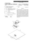
[0007] FIG. 1 is an exploded, isometric view of an exemplary embodiment of an attachment mechanism, together with an electronic component, wherein the attachment mechanism includes a fastener.
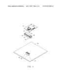
[0008] FIG. 2 is an enlarged view of the fastener of FIG. 1.
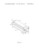
[0009] FIG. 3 is an assembled, isometric view of FIG. 1.
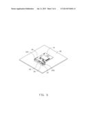
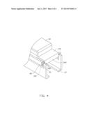
[0010] FIG. 4 is an isometric view of a part of a second embodiment of the fastener of FIG. 1.
DETAILED DESCRIPTION
[0011] The disclosure, including the accompanying drawings, is illustrated by way of example and not by way of limitation. It should be noted that references to "an" or "one" embodiment in this disclosure are not necessarily to the same embodiment, and such references mean at least one.
[0012] FIG. 1 shows an exemplary embodiment of an attachment mechanism for fastening an electronic component 10. The attachment mechanism includes a circuit board 30 and a fastener 20. The electronic component 10 includes a first connector 12 mounted to a first end of a bottom surface of the electronic component 10.
[0013] A second connector 32 is fastened to the circuit board 30. The second connector 32 includes a small mounting portion 31 fastened to the circuit board 30 and a large main body 35 on a top of the mounting portion 31.
[0014] FIG. 2 shows the fastener 20 including an engaging portion 21 and a rotating portion 26 rotatably connected to the engaging portion 21. The engaging portion 21 includes two opposite sidewalls 23 and a connection wall 25 connected between first ends of the sidewalls 23. The connection wall 25 extends out of tops of the sidewalls 23. Two bars 27 perpendicularly extend from bottoms of the corresponding sidewalls 23 toward each other. Two L-shaped hooks 232 extend up from second ends of the corresponding sidewalls 23, opposite to each other. The second ends of the sidewalls 23 are opposite to the first ends. The rotating portion 26 includes a U-shaped top wall 22, arched up. Two abutting walls 241 extend from opposite ends of the top wall 22, away from each other. One of the abutting walls 241 is perpendicularly and rotatably connected to the connection wall 25. A stop wall 242 extends down from a side of the other abutting wall 241 away from the top wall 22. Two U-shaped latching portions 243 extend from opposite ends of the stop wall 242, facing each other. The hooks 232 engage with the corresponding latching portions 243.
[0015] FIG. 3 shows in assembly, the sidewalls 23 are manipulated to allow the hooks 232 to be toward each other. The rotating portion 26 is rotated up to disengage the latching portions 243 from the corresponding hooks 232. The end of the fastener 20 away from the connection wall 25 aligns with an end of the second connector 32. The sidewalls 23 are manipulated away from each other, and then the fastener 20 is moved toward the second connector 32. When the connection wall 25 abuts against the main body 35, the sidewalls 23 are released to abut against opposite sides of the main body 35. The fastener 20 is manipulated up to allow the bars 27 to abut against opposite sides of a bottom of the main body 35. The rotating portion 26 is rotated up, the first connector 12 is connected to the second connector 32. The rotating portion 26 is rotated down to allow the latching portions 243 to engage with the corresponding hooks 232. The abutting walls 241 abut against a top of the electronic component 10. The stop wall 242 and the connection wall 25 abut against opposite sides of the first end of the electronic component 10.
[0016] FIG. 4 shows a second embodiment of the fastener 20. The rotating portion 26 is mounted to the second end of the engaging portion 21 in a different way. Two blocks 28 perpendicularly extend from opposite ends of the stop wall 242. A through slot 282 is defined in each block 28. An extension portion 29 perpendicularly extends up from the second end of each sidewall 23. A latch 291 protrudes from each extension portion 29 to engage in a corresponding through slot 282.
[0017] It is believed that the present embodiments and their advantages will be understood from the foregoing description, and various changes may be made thereto without departing from the spirit and scope of the description or sacrificing all of their materials advantages, the examples hereinbefore described merely being exemplary embodiments.
User Contributions:
Comment about this patent or add new information about this topic:
Images included with this patent application:
 |  |
 |  |
 |
| Similar patent applications: | |
| Date | Title |
|---|---|
| 2014-01-30 | Tilt mechanism for a monitor |
| 2014-02-06 | Cased electrical component |
| 2012-04-12 | Attachment mechanism |
| 2012-12-27 | Electronic component |
| 2013-01-10 | Electronic component |
| New patent applications in this class: | |
| Date | Title |
|---|---|
| 2019-05-16 | A method of manufacturing a component carrier |
| 2019-05-16 | Printed board joining method, electronic apparatus, and manufacturing method therefor |
| 2019-05-16 | Multi-led system |
| 2019-05-16 | Flexible electromagnetic shielding sheet and electronic device provided with same |
| 2016-09-01 | Electronic module power supply |
| New patent applications from these inventors: | |
| Date | Title |
|---|---|
| 2014-05-01 | Fan device |
| 2014-03-27 | Mounting device for hard disk drive |
| 2014-02-27 | Electronic device with fan module |
| 2014-01-09 | Front panel assembly with identification plate |
| 2013-12-26 | Electronic device and expansion card of the same |
| Top Inventors for class "Electricity: electrical systems and devices" | |
| Rank | Inventor's name |
|---|---|
| 1 | Zheng-Heng Sun |
| 2 | Levi A. Campbell |
| 3 | Li-Ping Chen |
| 4 | Robert E. Simons |
| 5 | Richard C. Chu |