Patent application title: PORTABLE EXTERNAL POWER-SUPPLYING DEVICE
Inventors:
Hung-Pin Shen (Tainan City, TW)
Lung-Hua Wu (Yuli Township, TW)
Yen-Ling Chen (Kaohsiung City, TW)
IPC8 Class: AH05K100FI
USPC Class:
361736
Class name: For electronic systems and devices module with printed circuit boards
Publication date: 2013-07-11
Patent application number: 20130176688
Abstract:
A portable external power-supplying device is disclosed. The portable
external power-supplying device implements a unique mechanism to
detachably assemble battery units whose number can be adjusted according
to user needs, which means the overall aggregate capacity of the portable
external power-supplying device is adjustable. The portable external
power-supplying device is adaptive to connect and charge a portable
electronic deviceClaims:
1. A portable external power-supplying device, comprising a power control
module 1 and one or more individual battery units 2, 3, 4, 5; the power
control module 1 having an enclosure 11 containing therein a circuit
board 12, the circuit board 12 including a charge controller loop 121, a
buck-boost converter loop 122, a power manager loop 123, a button switch
124, an indicator light set 125, a first port 126, a power inlet 127 and
a power outlet 128, the enclosure 11 having a back provided with a
positioning hole 13 and a fixing hole 14; each of the individual battery
units 2, 3, 4, 5 having an enclosure 21 atop provided with an
accommodating recess 22, the individual battery unit 2 including a
controller 23, a cell 24, a second port 25 and a third port 26, the
controller 23 being electrically connected to the cell 24, the second
port 25 and the third port 26, wherein the second port 25 faces the
accommodating recess 22 of the enclosure 21 and the third port third port
26 is provided at a side of the enclosure 21, the accommodating recess 22
of the enclosure 21 of the individual battery unit 2 having a positioning
pin 27 and a retaining hook 28, each of the individual battery units 2,
3, 4, 5 having a back provided with a positioning hole 271 and a fixing
hole 281 corresponding to the positioning pin 27 and the retaining hook
28 of another said individual battery unit 2, 3, 4 or 5, respectively;
for assembling the portable external power-supplying device, the power
control module 1 sliding into the accommodating recess 22 of the
individual battery unit 2 enclosure 21 such that the first port 126 of
the power control module 1 is electrically connected to the second port
25 open to the accommodating recess 22 of the individual battery unit 2,
while the positioning hole 13 and the fixing hole 14 of the power control
module 1 are engaged with the positioning pin 127 and the retaining hook
28 of the individual battery unit 2, respectively; after the power
control module 1 and the individual battery unit 2 is combined, the
second individual battery unit 3, the third individual battery unit 4 and
the fourth individual battery unit 5 are successively assembled so that
the second port 25 of one said individual battery unit 2, 3, 4 or 5 is
electrically connected to and posited by the third port 26 of another
said individual battery unit 2, 3, 4 or 5.
2. The portable external power-supplying device of claim 1, wherein in the power control module 1, the power inlet 127 is electrically connected to the charge controller loop 121, while the charge controller loop 121, the buck-boost converter loop 122 and the power manager loop 123 are electrically connected together, and the power manager loop 123 is electrically connected to the button switch 124 and the indicator light set 125 while the buck-boost converter loop 122 is electrically connected to the power outlet 128 and the first port 126.
3. The portable external power-supplying device of claim 1, wherein in the power control module 1, the button switch 124, the indicator light set 125, the first port 126, the power inlet 127 and the power outlet 128 of the circuit board 12 are exposed outside the enclosure 11 of the power control module 1 to be visible, accessible and operable to a user from exterior of the portable external power-supplying device.
4. The portable external power-supplying device of claim 1, wherein the power inlet 127 of the power control module 1 serves to connect a terminal of an external adapter and convey a DC power to the power control module 1 and the power outlet 128 of the power control module 1 serves to connect a power supply of an external portable electronic device to be charged.
5. The portable external power-supplying device of claim 1, wherein the first port 126 of the power control module 1 and the third port 26 of each said individual battery unit 2, 3, 4 or 5 are provided at backs of the enclosures 11, 21, respectively, so that the power control module 1 and the individual battery unit 2 and additional said individual battery units 3, 4, 5 are vertically stacked as an integral.
Description:
BACKGROUND OF THE INVENTION
[0001] 1. Technical Field
[0002] The present invention relates to external power supply for consumer electronics, and more particularly, to a power-supplying device adaptive to connect a portable electronic device and act as a backup power source that provides a variable power capacity.
[0003] 2. Description of Related Art
[0004] Currently, a rechargeable battery is a common power source for various portable consumer electronics, such as mobile phones, laptops, digital cameras, music players, etc.
[0005] For charging such a rechargeable battery, a specific charger is required to adjust the AC power from the power grid into a certain potential. Where the power grid is inaccessible, charging is impossible and the portable device using the battery cannot serve when the battery is exhausted.
[0006] To avoid this plight, a portable power supply, or a "power pack", has been developed. By using the same, users can charge their consumer electronics everywhere despite the accessibility of the power grid.
[0007] The existing portable power supply is mainly composed of a rechargeable battery and a control circuit that are packed in an enclosure. The commercialized products are provided with different battery capacities. While a portable power supply having a small capacity is usually compact and light, it cannot serve long. On the other hand, a portable power supply having a small capacity serves long yet is bulky and less portable. In addition, the existing rechargeable battery has its life subject to its age and/or frequency of use and once the battery become poor in performance or broken, the whole power supply is unusable.
SUMMARY OF THE INVENTION
[0008] In view of the shortcomings of the prior-art device as stated above, the present invention provides a portable external power-supplying device with a variable power capacity. The power-supplying device has detachably combined battery units whose number can be adjusted according to user needs, which means the overall volume and weight of the power-supplying device is manageable. The individual battery units are replaceable, so the performance of the power-supplying device can be easily maintained. This helps to preserve resources.
[0009] To this end, according to the present invention, a portable external power-supplying device comprises a power control module and one or more battery units whose aggregate capacity is variable. The power control module includes a circuit board, an indicator light set, a first port, a power inlet, a power outlet and others. The individual battery unit includes a controller, a cell, a second port and a third port.
[0010] When communicated with the battery units, the control module charges the battery units through the power inlet for later use. In use, the control module supplies power to a portable electronic device through the power outlet.
[0011] The control module can charge one or more battery units. These charged battery units can be easily assembled or separated so that one or more battery units can be used to charge according to practical needs. As each battery is subject to its cycle life, once any of the individual battery units is out of use, the power-supplying device can be replenished by replacing the broken battery unit with a new one. As compared with retiring the whole prior-art device, this significantly reduces costs and is friendlier to the environment.
BRIEF DESCRIPTION OF THE DRAWINGS
[0012] The invention as well as a preferred mode of use, further objectives and advantages thereof will be best understood by reference to the following detailed description of illustrative embodiments when read in conjunction with the accompanying drawings, wherein:
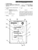
[0013] FIG. 1 is a top view of an individual battery unit according to the present invention;
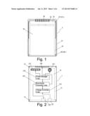
[0014] FIG. 2 is a schematic drawing illustrating a power control module according to the present invention;
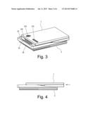
[0015] FIG. 3 is a perspective view of the assembled power control module and individual battery unit according to the present invention;
[0016] FIG. 4 is a lateral view of the assembly of FIG. 3;
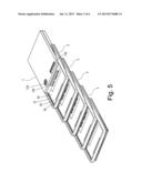
[0017] FIG. 5 shows the power control module and plural said individual battery units to be assembled;
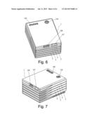
[0018] FIG. 6 is a perspective view of the assembled power control module and individual battery units according to the present invention;
[0019] FIG. 7 is another perspective view of the assembly of FIG. 6;
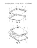
[0020] FIG. 8 is a schematic drawing showing the power control module to be stacked with the individual battery;
[0021] FIG. 9 is another schematic drawing showing the power control module to be stacked with the individual battery unit; and
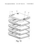
[0022] FIG. 10 is a schematic drawing showing the power control module to be stacked with plural said individual battery unit.
DETAILED DESCRIPTION OF THE INVENTION
[0023] Referring to FIG. 1 and FIG. 2, in the present invention, a portable external power-supplying device primarily comprises a power control module 1 and one or more individual battery units 2, 3, 4, 5.
[0024] As shown in FIG. 2, the power control module 1 has an enclosure 11 containing therein a circuit board 12. On the circuit board 12, there are a charge controller loop 121, a buck-boost converter loop 122, a power manager loop 123, a button switch 124, an indicator light set 125, a first port 126, a power inlet 127 and a power outlet 128. The enclosure 11 has its back provided with a positioning hole 13 and a fixing hole 14.
[0025] The power inlet 127 of the power control module 1 is electrically connected to the charge controller loop 121, while the charge controller loop 121, the buck-boost converter loop 122, and the power manager loop 123 are electrically connected together. The power manager loop 123 is electrically connected to the button switch 124 and the indicator light set 125. Meantime, the buck-boost converter loop 122 is electrically connected to the power outlet 128 and the first port 126.
[0026] The button switch 124, the indicator light set 125, the first port 126, the power inlet 127, and the power outlet 128 of the circuit board 12 are exposed outside the enclosure 11 of the power control module 1 to be visible, accessible and operable to a user from exterior.
[0027] Therein, the power inlet 127 is adaptive to connect a terminal of an adapter and input a DC power to the power control module 1. The power outlet 128 is adaptive to connect a battery of a portable electronic device that is to be charged.
[0028] As shown in FIG. 1, the enclosure 21 of each of the individual battery units 2, 3, 4, 5 has its top formed with an accommodating recess 22. The individual battery unit 2 has therein a controller 23, a cell 24, a second port 25 and a third port 26. The controller 23 is electrically connected to the cell 24, the second port 25 and the third port 26. The second port 25 faces the accommodating recess 22 of the enclosure 21, and the third port 26 is located at a side of the enclosure 21. The enclosure 21 of the individual battery unit 2 has a positioning pin 27 and a retaining hook 28 in the accommodating recess 22. Each of the individual battery units 2, 3, 4, 5 has its back provided with a positioning hole 271 and a fixing hole 281 corresponding to the positioning pin 27 and the retaining hook 28 on another said individual battery unit, respectively.
[0029] As shown in FIG. 3 and FIG. 4, to assemble the components, the power control module 1 slides into the accommodating recess 22 of the enclosure 21 of the individual battery unit 2, such that the first port 126 of the power control module 1 gets electrically connected to the second port 25 open to the accommodating recess 22 of the individual battery unit 2, and, at the same time, the positioning hole 13 and the fixing hole 14 of the power control module 1 get engaged with the positioning pin 127 and the retaining hook 28 of the individual battery unit 2, respectively.
[0030] As shown in FIG. 5 through FIG. 7, after the power control module 1 is assembled with the individual battery unit 2, the second individual battery unit 3, third individual battery unit 4, fourth individual battery unit 5 and so on can be successively combined in the manner described previously to make the second port 25 of one battery unit electrically connected to and positioned by the third port 26 of another battery unit.
[0031] By doing so, the device of the present invention can have the number of the individual battery units 2, 3, 4, 5 increased or decreased according to practical needs. Such a slide-in operation as shown in FIG. 5 through FIG. 7 allows a user to use as many battery units as he/she needs. The individual battery units 2, 3, 4, 5 thus assembled are convenient to carry for the user to charge his/her portable electronic devices anywhere and anytime.
[0032] Referring to FIG. 8 and FIG. 10, the power control module 1 and each of the individual battery units 2, 3, 4, 5 may alternatively have their first port 126 and third port 26 located at the backs of their enclosures 11, 21, respectively. In such a case, the user can assemble the power control module 1 and the individual battery unit 2 and/or the additional battery units 3, 4, 5 through a stacking operation instead of the foregoing slide-in operation where the components are stacked vertically as an integral.
User Contributions:
Comment about this patent or add new information about this topic:
Images included with this patent application:
 |  |
 |  |
 |  |
 |
| Similar patent applications: | |
| Date | Title |
|---|---|
| 2013-07-04 | Method for providing power supply, and a power supply device |
| 2013-07-11 | Portable terminal with support plate |
| 2012-02-02 | Portable networking device |
| 2013-06-20 | Portable terminal device |
| 2011-04-14 | Stand-up external data access device |
| New patent applications in this class: | |
| Date | Title |
|---|---|
| 2016-12-29 | Assembly structure and electronic device having the same |
| 2016-06-30 | Stacked package structure |
| 2016-06-02 | Electronic assembly and method of manufacturing same |
| 2016-05-26 | Printed circuit board copper plane repair |
| 2016-03-10 | Module |
| Top Inventors for class "Electricity: electrical systems and devices" | |
| Rank | Inventor's name |
|---|---|
| 1 | Zheng-Heng Sun |
| 2 | Levi A. Campbell |
| 3 | Li-Ping Chen |
| 4 | Robert E. Simons |
| 5 | Richard C. Chu |