Patent application title: FIXING APPARATUS FOR WAVEGUIDE PLATE
Inventors:
Jun-Wei Wang (Shenzhen City, CN)
Jun-Wei Wang (Shenzhen City, CN)
IPC8 Class: AH05K700FI
USPC Class:
2483091
Class name: Supports brackets article holding means
Publication date: 2013-05-02
Patent application number: 20130105654
Abstract:
A fixing apparatus for fixing a waveguide plate includes a number of
conductive fixing members fixed to corresponding sides of the waveguide
plate, and a bracket. Each fixing member includes a fixing portion having
an identical length to the corresponding sidewall and a resilient
abutting portion extending from a side of the fixing portion. Each fixing
portion is in tight contact with the corresponding side of the waveguide
plate. The waveguide plate is received in the bracket. The resilient
abutting portions resiliently abut against an inner surface of the
bracket.Claims:
1. A fixing apparatus for a waveguide plate, the fixing apparatus
comprising: a plurality of conductive fixing members respectively fixed
to corresponding sides of the waveguide plate, each fixing member
comprising a fixing portion having the same length as the corresponding
side to tightly contact the corresponding side of the waveguide plate,
and a resilient abutting portion extending from a side of the fixing
portion; and a bracket comprising a plurality of sidewalls to receive the
waveguide plate and the fixing members among the sidewalls, wherein the
resilient abutting portions resiliently abut against inner surfaces of
the corresponding sidewalls.
2. The fixing apparatus of claim 1, wherein the number of corresponding sides of the waveguide plate is four, and the sidewalls of the bracket comprise two opposite first sidewalls and two opposite second sidewalls connected between corresponding ends of the first sidewalls, a wedged-shaped block protrudes from an inner surface of each first sidewall, adjacent to a front side of the first sidewall and blocking a front side of a corresponding fixing member.
3. The fixing apparatus of claim 2, wherein a bar is connected between rear sides of the second sidewalls, blocking a rear side surface of the waveguide plate.
4. The fixing apparatus of claim 1, wherein each resilient abutting portion is arc-shaped, and extends towards an opposite side of the fixing portion.
5. The fixing apparatus of claim 1, wherein the fixing portions are welded to the corresponding sides of the waveguide plate.
Description:
BACKGROUND
[0001] 1. Technical Field
[0002] The present disclosure relates to an apparatus for fixing a waveguide plate.
[0003] 2. Description of Related Art
[0004] The chassis of an electrical device generally defines a plurality of holes for dissipating heat, which easily leads to a leakage problem of electromagnetic waves. To solve the problem, a waveguide plate is fixed to the chassis. However, the waveguide plate is generally fixed to the chassis with screws, leaving a clearance between the waveguide plate and the chassis. Electromagnetic waves generated by the electrical device can escape through the clearance.
BRIEF DESCRIPTION OF THE DRAWINGS
[0005] Many aspects of the present embodiments can be better understood with reference to the drawings. The components in the drawings are not necessarily drawn to scale, the emphasis instead being placed upon clearly illustrating the principles of the present embodiments. Moreover, in the drawing, all the views are schematic, and like reference numerals designate corresponding parts throughout the several views.
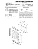
[0006] FIG. 1 is an exploded, isometric view of an exemplary embodiment of a fixing apparatus together with a waveguide plate, wherein the fixing apparatus includes four fixing members.
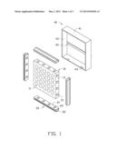
[0007] FIG. 2 is an assembled, isometric view of the waveguide plate and the fixing members of FIG. 1.
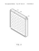
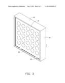
[0008] FIG. 3 is an assembled, isometric view of the fixing apparatus and waveguide plate of FIG. 1.
DETAILED DESCRIPTION
[0009] The disclosure, including the accompanying drawings, is illustrated by way of example and not by way of limitation. It should be noted that references to "an" or "one" embodiment in this disclosure are not necessarily to the same embodiment, and such references mean at least one.
[0010] Referring to FIG. 1, an exemplary embodiment of a fixing apparatus for fixing a waveguide plate 10 includes four conductive fixing members 20 and a bracket 40.
[0011] The waveguide plate 10 is rectangular. The waveguide plate 10 defines a plurality of through holes 11 extending through opposite side surfaces of the waveguide plate 10. A plurality of protrusions 15 protrudes from each of four sidewalls 13 each perpendicularly connected between corresponding sides of the side surfaces.
[0012] The fixing members 20 have the same lengths as the corresponding sidewalls 13. Each fixing member 20 includes an elongated fixing portion 21, and an arc-shaped resilient abutting portion 22 extending from a first side of the fixing portion 21 towards a second side of the fixing portion 21 opposite to the first side. The fixing portion 21 defines a plurality of spaced mounting holes 23, corresponding to the protrusions 15 of the corresponding sidewall 13.
[0013] The bracket 40 is a rectangular frame, including two opposite first sidewalls 41 and two opposite second sidewalls 42 perpendicularly connected between corresponding ends of the first sidewalls 41. Two wedged-shaped blocks 43 protrude from the inner surface of each first sidewall 41, adjoining the front side of the bracket 40. The slanting wall of each block 43 is arranged at the front side of the block 43. A bar 45 is connected between middle rear sides of the second sidewalls 42.
[0014] Referring to FIGS. 2 and 3, in assembly, the protrusions 15 are respectively extended through the mounting holes 23, to allow the fixing portions 21 to be in tight contact with the corresponding sidewalls 13. The protrusions 15 are welded to the corresponding fixing portions 21. The waveguide plate 10 together with the fixing members 20 is placed into the bracket 40 from the front side of the bracket 40. The blocks 43 block the front sides of the corresponding fixing members 20. The bar 45 blocks the rear side of the waveguide plate 10. The resilient abutting portions 22 resiliently abut against the inner surfaces of the corresponding first sidewalls 41 and second sidewalls 42.
[0015] Because the fixing portions 21 are in tight contact with the corresponding sidewalls 13, and the resilient abutting portions 22 are in tight contact with the inner surface of the corresponding first sidewalls 41 and second sidewalls 42, leaving almost no clearance between the waveguide plate 10 and the bracket 40. The fixing members 20 are conductive, so the fixing members 20 have an effect of electromagnetic wave attenuation. Therefore, the fixing apparatus is good at preventing electromagnetic leakage.
[0016] To detach the waveguide plate 10 from the bracket 40, the top and bottom resilient abutting portions 22 are deformed toward the waveguide plate 10. Then the waveguide plate 10 is pushed forward, the waveguide plate 10 together with the fixing members 20 can be taken out of the bracket 40.
[0017] Even though numerous characteristics and advantages of the embodiments have been set forth in the foregoing description, together with details of the structure and the functions of the embodiments, the disclosure is illustrative only, and changes may be made in details, especially in the matters of shape, size, and arrangement of parts within the principles of the embodiments to the full extent indicated by the broad general meaning of the terms in which the appended claims are expressed.
User Contributions:
Comment about this patent or add new information about this topic:
| People who visited this patent also read: | |
| Patent application number | Title |
|---|---|
| 20190162665 | ANALYSIS METHOD AND SYSTEM FOR ANALYZING A NUCLEIC ACID AMPLIFICATION REACTION |
| 20190162664 | DEVICE FOR OPTICALLY EXCITING FLUORESCENCE |
| 20190162663 | Methods, Systems, and Devices for Measuring in Situ Saturations of Petroleum and NAPL in Soils |
| 20190162662 | SUBSTRATES WITH INDEPENDENTLY TUNABLE TOPOGRAPHIES AND CHEMISTRIES FOR QUANTIFIABLE SURFACE-INDUCED CELL BEHAVIOR |
| 20190162661 | MICRO OBJECT DETECTION APPARATUS |
Images included with this patent application:
 |  |
 |  |
| Similar patent applications: | |
| Date | Title |
|---|---|
| 2009-03-05 | Pumping apparatus |
| New patent applications in this class: | |
| Date | Title |
|---|---|
| 2016-02-25 | Method for producing an instrument panel support |
| 2015-10-15 | Toy display frame with restickable surface |
| 2015-05-21 | Expansion joint bracket |
| 2015-04-30 | Surgical sponge distribution systems and methods |
| 2015-04-23 | Mounting driver for undermounted sinks |
| New patent applications from these inventors: | |
| Date | Title |
|---|---|
| 2014-04-10 | Waveguide member |
| 2013-12-19 | Memory card module with electromagnetic radiation shield |
| 2013-06-27 | Connector with decreased electromagnetic radiation emmission |
| 2013-06-06 | Chassis for electronic device |
| 2013-04-04 | Video graphics array connector |
| Top Inventors for class "Supports" | |
| Rank | Inventor's name |
|---|---|
| 1 | Jeffrey D. Carnevali |
| 2 | Yun-Lung Chen |
| 3 | Wen-Tang Peng |
| 4 | Zheng-Heng Sun |
| 5 | Zhan-Yang Li |