Patent application title: COLLAPSIBLE BOTTLE
Inventors:
David B. Haynie (Palo Alto, CA, US)
IPC8 Class: AB65D3700FI
USPC Class:
220 6
Class name: Receptacles sectional folding
Publication date: 2013-03-28
Patent application number: 20130075393
Abstract:
A collapsible fluid container having an expanded and a collapsed
configuration, including a rigid top portion having an open mouth with
structure onto which a closure member may be disposed, a rigid base
portion bottom, and a resilient medial portion disposed between the upper
portion and base portion. When in the expanded configuration the
container is substantially cylindrical. It is placed into a collapsed
configuration by twisting the upper portion and base portion in relation
to one another or pushing the upper portion toward the base portion until
they approximate one another. Retention structure is employed to hold the
container in the collapsed configuration. When the retention structure is
disengaged, the resilient material of the medial portion urges the
container back into a fully expanded configuration.Claims:
1. A collapsible fluid container having an expanded and a collapsed
configuration, comprising: a generally rigid top portion having an open
mouth with structure onto which a closure member may be disposed; a
generally rigid base portion having a bottom with a planar portion for
placement on a flat surface; a flexible and resilient medial portion
disposed between said upper portion and said base portion; and retention
structure for securing the container in the collapsed configuration;
wherein when in the expanded configuration said collapsible fluid
container is substantially cylindrical, and said apparatus is placed into
a collapsed configuration by removing any closure member from said mouth
and then either twisting said upper portion and said base portion in
relation to one another or pushing said upper portion toward said base
portion until said retention structure is engaged so as to hold said
fluid container in the collapsed configuration.
2. The fluid container of claim 1, wherein said medial portion is fabricated from food grade silicone rubber.
3. The fluid container of claim 1, wherein said medial portion has an upper edge connected to a lower rim of said upper portion and a lower edge connected to an upper rim of said base portion.
4. The fluid container of claim 3, wherein the diameters of said upper rim and said lower rim and the diameter of said medial portion at the points of connection are substantially the same.
5. The fluid container of claim 3, wherein said upper portion is sized to nest snugly into said base portion, such that when said fluid container is twisted or pushed into the collapsed configuration said base portion captures and retains said upper portion.
6. The fluid container of claim 1, wherein said upper portion has a lower rim with a diameter and said base portion has an upper rim with a diameter substantially the same as the diameter of said lower rim, and wherein to move said fluid container from a fully expanded configuration to a fully collapsed configuration, said closure member is removed so as to allow air to escape and then rotating said upper portion in relation to said base portion, such that said flexible and resilient medial portion folds and overlaps itself within the confines of the upper and lower portions until said lower rim and said upper rim are generally approximated, thereby bringing said retention elements into engagement, thereby securing said fluid container in the collapsed configuration.
7. The fluid container of claim 6, wherein said retention structure comprises a female element disposed on either of said upper or base portions and a male element disposed on either of said upper or base portions and insertable into said male element, wherein to engage said male element with said female element said upper portions is twisted such that said male element slightly bypasses said female element sufficiently for the male element to insert into the female element as said flexible and resilient medial portion urges said upper and said base portions to rotate and maintain the insertion.
8. The fluid container of claim 6, wherein said retention structure comprises a resilient band.
9. The fluid container of claim 1, wherein said retention structure comprises a resilient band.
10. The fluid container of claim 1, wherein said upper portion has a lower rim with a contoured edge and said base portion has an upper rim with a contoured edge complementary to the contoured edge of said lower rim, and wherein to move said fluid container from a fully expanded configuration to a fully collapsed configuration, said closure member is removed so as to allow air to escape and then rotating said upper portion in relation to said base portion, such that said flexible and resilient medial portion folds and overlaps itself within the confines of the upper and lower portions until said lower rim and said upper rim are generally approximated, thereby bringing said contoured edges of said upper and lower rims into contact so as to prevent twisting of said medial portion in a direction opposite that of the direction in which it was twisted to collapse.
11. The fluid container of claim 1, wherein said upper portion includes a rounded overhang spaced apart from said medial portion, said overhang including a circumferential interior rim, and where said base portion includes an exterior circumferential rim that engages said circumferential interior rim when said fluid container is placed in the collapsed configuration to prevent the top and bottom portions from separating from one another.
12. The fluid container of claim 1, wherein said upper portion has a slightly smaller outside diameter than the interior diameter of said base portion, such that when said upper portion is twisted or pushed in relation to said base portion, said medial portion collapses and folds within the confines of the base portion and said upper portion fits snugly within said folds of said medial portion.
13. The fluid container of claim 12, wherein said base portion is fabricated from silicone rubber and is integral with said medial portion, and wherein said base portion has a thickness slightly greater than the thickness of said medial portion such that it is sufficiently rigid to capture and retain said upper portion and to retain the bottle in a collapsed configuration.
14. The fluid container of claim 1, wherein said upper portion has an inner diameter larger than the exterior diameter of said base portion, such that when said upper portion is twisted or pushed in relation to said base portion, said medial portion collapses and folds within the confines of said upper portion and said bottom portion fits snugly within said base portion.
15. A collapsible fluid container, comprising: an upper portion having an open mouth; a base portion; a medial portion fabricated from resilient material, said medial portion disposed between said upper portion and said base portion; and retention structure; wherein said fluid container has an expanded configuration and a collapsed storage configuration and is translated from the expanded configuration to the collapsed configuration by twisting said upper portion in relation to said base portion, and wherein when said fluid container is in the collapsed configuration, said resilient material imparts a force to each of said upper and base portions urging said upper and base portions to rotate in a direction opposite that of the rotation of twist used to place said fluid container in the collapsed configuration, and said retention elements uses such force as a means to maintain engagement with one another and thereby to retain said fluid container in the collapsed configuration.
16. The fluid container of claim 15, wherein said retention structure comprises complementary clasp elements disposed on each of said upper portion and said base portion.
17. The fluid container of claim 15, wherein said retention structure comprises a resilient band.
18. The fluid container of claim 15, wherein said retention structure comprises a contoured lower edge in said upper portion and a contoured upper edge in said base portion that engage one another when said fluid container is in said collapsed configuration prevent rotation of said upper portion in relation to said base portion.
19. The fluid container of claim 15, wherein said upper portion and said base portion have different diameters, such that when said fluid container is placed into the collapsed configuration, either of said upper portion or said lower portion fits within the other of said upper portion or said base portion.
20. A collapsible fluid container, comprising: an upper portion with a mouth; a base portion shaped for placement on a flat surface such that said fluid container is in a generally upright orientation; a medial portion fabricated from resilient material and disposed between said upper portion and said base portion; wherein said fluid container has an expanded configuration and a collapsed configuration, and when in the collapsed configuration said medial portion is distorted so as to reduce the volume within said fluid container and so as to bring said upper portion and said lower portion into engagement with one another, and wherein when said upper portion and said lower portion are released from such engagement, said resilient material will urge said fluid container back into the expanded configuration.
Description:
CROSS REFERENCES TO RELATED APPLICATIONS
[0001] The present application claims priority to U.S. Provisional Patent Application Ser. No. 61/524,201, filed 08/16/2011 (Aug. 16, 2011).
STATEMENT REGARDING FEDERALLY SPONSORED RESEARCH OR DEVELOPMENT
[0002] Not applicable.
NAMES OR PARTIES TO A JOINT RESEARCH AGREEMENT
[0003] Not applicable.
INCORPORATION-BY-REFERENCE OF MATERIAL SUBMITTED ON A COMPACT DISC
[0004] Not applicable.
BACKGROUND OF THE INVENTION
[0005] 1. Field of the Invention
[0006] The present invention relates generally to fluid containers, and more specifically to collapsible fluid containers, and more particularly still to a fluid container that can be repeatedly moved between an expanded configuration for holding fluid and a collapsed configuration for compact storage and easy transport.
[0007] 2. Background Discussion
[0008] The need for regular and sufficient hydration has people increasingly carrying a ready supply of water or other fluids. Runners, hikers, backpackers, skiers, cyclists, tourists and sightseers, hunters and fishermen, airline travelers, and the like, now routinely carry water bottles containing plain water or (ofttimes) electrolyte replacement fluids. To facilitate ease in carrying such bottles, a number of vendors offer bottle carrying apparatus, such as grips for handheld water bottles, hip and backpacks for hydration packs that hold bottles, and hands free hydration systems, typically comprising a pack for holding a water bladder to which a lengthy straw is connected (such as many versions of the now famous CAMELBAK®), [CAMELBAK is a registered trademark of Camelbak, Inc, of Petaluma, Calif.]
[0009] There are, of course, numerous uses for bottles other than for carrying fluids into environments where fluid is not readily available. For instance, bottles are everywhere employed as simple fluid or food storage containers. Reusable food and fluid storage containers minimize waste, reduce the volume of products that find their way into landfills, reduce energy required to manufacture the containers, and so forth.
[0010] In both environments of use, there arises the problem of what to do with the bottle when it is emptied of its contents. When a runner, cyclist, hunter, backpacker or other outdoors sportsman empties a water bottle (or numerous water bottles), he or she generally carries those bottles home. As anyone who has done this can attest, there is no small measure of irritation associated with having to carry one or more large empty bottles over a long distance, sometimes with the bottle bouncing and clanging annoyingly against one's body or pack. In the home, while there is no significant inconvenience associated with having to carry around an empty bottle; it is instead the clutter connected with loose and empty containers that causes the irritation and inconvenience. And unless a container is capable of nesting in other food/fluid storage containers, considerable space may be required to store empty storage containers. This, too, is a longstanding source of irritation.
[0011] There is therefore a need for a fluid container that when emptied can be collapsed or otherwise configured such that it takes up much less space than when filled and that can be easily carried in a pocket or stored in large numbers in a drawer.
[0012] Several vendors of hydration systems have developed collapsible bottles, including Vapur, Prima Bottled Water, Platypus, and others. There are also a number of patent publications that teach collapsible bottles of one kind or another, including U.S. Pat. No. 4,930,644, to Robbins, III, which discloses a collapsible thin film plastic container that includes a unitary extrusion blow molded container body having a cylindrical side wall, and a closed lower end and an open upper end. The side wall has thickened upper and lower minor portions, the upper minor portion provided with means for receiving a removable lid. The thickened upper and lower portions permit the container to remain in a substantially upright, self-supporting position, but permit the main peripheral side wall portion to collapse upon exertion of an axially directed compressive force.
[0013] Further, U.S. Pat. No. 5,226,551, also to Robbins, III, teaches a reusable and re-collapsible one-piece container having telescoping portions in a peripheral side wall that permits collapse from an extended to a collapsed condition.
[0014] Yet another patent to Robbins, III, U.S. Pat. No. 5,549,213, shows a reusable re-collapsible container and re-sealable cap that includes a one-piece, extruded and blow molded container formed with a peripheral side wall divided into upper, intermediate and lower portions, with the upper and lower portions having significantly greater wall thicknesses than the intermediate portion, all of which permits the intermediate portion to reverse fold as the upper and lower portions are moved toward one another in a telescoping relationship.
[0015] U.S. Pat. No. 4,875,576 teaches a container having a medial sidewall portion with a bellows-type configuration to permit selective collapse and extension of the container. It employs helical creases which spiral or angle between first and second portions of the container side wall to facilitate collapse.
[0016] U.S. Pat. No. 4,873,100 describes an expandable plastic bottle that also employs a bellows-type side wall.
[0017] U.S. Pat. No. 2,880,902 discloses a collapsible, drinking cup having a side wall with alternating thick and thin portions.
[0018] U.S. Pat. Appl. Pub. No. 20050017015, by Higuchi, shows a collapsible container including a top tap, a small width in the height direction at the bottom, and a horizontal bellows formed on the whole or part in a longitudinal direction of the container body, except the top tap, and the width in the height direction.
[0019] These publications and products reflect the current state of the art of which the present inventor is aware. Reference to, and discussion of, these publications is intended to aid in discharging Applicant's acknowledged duty of candor in disclosing information that may be relevant to the examination of claims to the present invention. However, it is respectfully submitted that none of the above-indicated publications disclose, teach, suggest, show, or otherwise render obvious, either singly or when considered in combination, the invention described and claimed herein.
BRIEF SUMMARY OF THE INVENTION
[0020] The present invention is a collapsible fluid container having an expanded configuration and a collapsed configuration. The apparatus includes a relatively rigid upper portion with a mouth, a relatively rigid base portion, and a medial portion fabricated from resilient material and disposed between the upper portion and base portion. When in the collapsed configuration, the medial portion is distorted so as to reduce the volume within the fluid container so as to bring the upper portion into engagement with the lower portion. Retention structure disposed on the upper and lower portions may be engaged and employed to secure the container in the collapsed configuration, or an element physically separable from the container may also be so employed (a resilient band, for instance). When the retention element(s) are disengaged and the upper portion and lower portion are allowed to separate from one another, the resilient material of the medial portion urges the container back into a fully extended and expanded configuration.
[0021] This summary broadly sets out the essential and important features of the present invention so that the detailed description that follows may be better understood, and so that the present contributions to the art may be better appreciated. There are additional features of the invention that will be described in the detailed description of the preferred embodiments of the invention which will form the subject matter of the claims appended hereto.
[0022] Accordingly, before explaining the preferred embodiment of the disclosure in detail, it is to be understood that the disclosure is not limited in its application to the details of the construction and the arrangements set forth in the following description or illustrated in the drawings. The inventive apparatus described herein is capable of other embodiments and of being practiced and carried out in various ways. As such, those skilled in the art will appreciate that the conception, upon which this disclosure is based may readily be used as a basis for designing other structures, methods, and systems for carrying out the several purposes of the present invention. It is important, therefore, that the claims are regarded as including such equivalent constructions as far as they do not depart from the spirit and scope of the present invention.
[0023] For a better understanding of the present invention, its advantages and the specific objects attained by its uses, reference should be made to the accompanying drawings and descriptive matter in which there are illustrated the preferred embodiment.
BRIEF DESCRIPTION OF THE SEVERAL VIEWS OF THE DRAWINGS
[0024] The invention will be better understood and objects other than those set forth above will become apparent when consideration is given to the following detailed description thereof. Such description makes reference to the annexed drawings wherein:
[0025] FIG. 1 is side view in elevation of the collapsible bottle of the present invention, showing the bottle in the full expanded configuration and with a cap installed over the top opening;
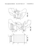
[0026] FIG. 1B is a side view in elevation showing the cap removed and a user in the process of twisting the collapsible bottle into a collapsed configuration;
[0027] FIG. 1C is a side view in elevation showing the bottle in a collapsed configuration and retained in this configuration with one or more integral clasps;
[0028] FIG. 1D is a schematic top plan view showing the twisting pattern for moving the bottle from the expanded to the collapsed configuration;
[0029] FIG. 2 is a cross-sectional side view in elevation of the inventive collapsible bottle in the expanded configuration;
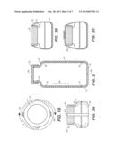
[0030] FIGS. 3A-3C are schematic side views in elevation showing an alternative means of retaining the bottle in the collapsed configuration, in this instance employing a resilient band;
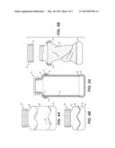
[0031] FIG. 4A is a schematic side views in elevation showing an alternative embodiment of the present invention in the expanded configuration, this embodiment having alternative means of retaining the bottle in the collapsed configuration, in this instance employing contoured upper and lower rigid portions that mate and couple to prevent rotation of the portions in relation to one another;
[0032] FIG. 4B is a side view in elevation showing the bottle of FIG. 4A in the collapsed configuration;
[0033] FIG. 5A is a cross-sectional side view in elevation showing another preferred embodiment of the inventive collapsible bottle having snap-fit and friction retention means for keeping the bottle in a collapsed configuration;
[0034] FIG. 5B is a partial cross-sectional side view in elevation showing the bottle of FIG. 5A as it is being twisted into a collapsed configuration and showing an upper portion overhang and rim configuration in cross-section;
[0035] FIG. 5C is a schematic partial cross-sectional side view showing the bottle of FIGS. 5A-5B in the fully collapsed configuration and with the upper portion overhang rim capturing the base portion rim;
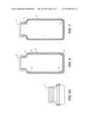
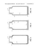
[0036] FIGS. 6-10 are each cross-sectional side views in elevation showing various ways of molding and assembling the relatively rigid and the flexible/resilient bottle components;
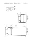
[0037] FIG. 11A is a cross-sectional side view in elevation of another alternative embodiment of the collapsible bottle of the present invention, this view showing the bottle in the fully expanded configuration;
[0038] FIG. 11B is a cross-sectional side view in elevation showing the bottle of FIG. 11A in the collapsed configuration;
[0039] FIG. 12 is a detailed cross-sectional side view taken along section line 12-12 of FIG. 11A;
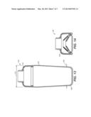
[0040] FIG. 13 is a cross-sectional side view in elevation of another embodiment of the inventive collapsible bottle, shown in the fully expanded configuration; and
[0041] FIG. 14 shows the bottle of FIG. 13 in the collapsed configuration.
DETAILED DESCRIPTION OF THE INVENTION
[0042] FIGS. 1-2 illustrate a first preferred embodiment of the inventive collapsible fluid container or bottle, generally denominated 10, herein. These views, collectively, show that the novel apparatus includes a generally rigid upper portion 12 having a mouth 14 preferably with male threads 16 suitable for closure with a cap 18 having complementary female threads 20. A snap fit or hinged lid may also be employed as a closure member. The bottle further includes a generally rigid bottom 22 having a substantially planar base 24, or a planar portion of a base, such that the container can be stably placed on a flat surface to stand in a substantially upright orientation.
[0043] Disposed between the upper and base portions is a flexible and resilient medial portion 26, preferably fabricated from food grade silicone rubber, and having an upper edge 28 and a lower edge 30 connected to the upper and lower portions, respectively, either by being welded to, incorporated into, or both, the lower rim 32 of the upper portion 12 and the upper rim 34 of the lower portion 22, each of which are made from generally or relatively rigid material (the rigidity being relative to the flexible and resilient medial portion). In a preferred embodiment, the diameters of the lower and upper rims and the medial portion at these points of connection are substantially the same. In an alternative embodiment, the upper portion may be slightly smaller than that of the base portion so as to provide a snug fit of the former into the latter when the medial portion is folded and collapsed down. As will be appreciated, the medial portion is generally cylindrical in shape, though a contoured medial portion having either a slightly tapering or a slightly bulging waist region 36 are possible without materially affecting apparatus function.
[0044] The bottle may be moved from a fully expanded and extended configuration (FIG. 1A) to a fully collapsed and stored configuration (FIG.1C). This is accomplished by removing the cap 18 (to allow air escape the collapsing and decreasing volume) and then rotating the upper portion 12 in relation to the base portion 22 (in this instance, clockwise as viewed from above). As the twisting proceeds, the medial portion 26 begins to fold and overlap itself within the confines of the rims of the upper and lower portions 12, 22, until the lower rim 32 of the upper portion and the upper rim 34 of the base portion are substantially approximated, at which time the medial portion 26 will be in a generally folded and collapsed state and contained within the volume formed by the coupled upper and base portions (see FIG. 1C). This will also bring retention structures into contact so that the apparatus can be maintained in the collapsed configuration. Such retention structure may include male elements 38, 40, and the female elements 42, 44 of one or more clasps 46, 48. The upper and base portions can be twisted such that the male element bypasses the female opening just sufficiently for the male element to insert into the female element as the resilient silicone material seeks to resume its untwisted state and thereby urges the upper and base portions to rotate in a counterclockwise direction (i.e., the opposite direction of that involved in the twisting collapse) and to spring back into an expanded configuration. In so doing, and provided with such potential energy, the clasp is brought into a locked configuration (FIGS. 1C-1D) that will retain the bottle in a collapsed configuration.
[0045] FIGS. 3A-3C show an alternative embodiment 50 of the present invention, in which a resilient band or keeper 52 is employed as a retention element to keep the bottle in the collapsed configuration when the resilient silicone medial portion 26 is twisted down in the manner described in connection with FIGS. 1-2. The band may be kept in a generally centered positioned by channels 54, 56 in the cap and base portions, shown in FIG. 2. In an alternative approach 58 (FIG. 3c) the resilient keeper band may be affixed to the top of the cap and provided with hook and loop material or similar fastening material that obviates the need for a channel in the cap and base portions.
[0046] FIGS. 4A-4B show another embodiment of the inventive bottle 60, this iteration including an alternative means of retaining the upper portion 62 and base portion 64 in the collapsed configuration. These means include a contoured lower edge 66 of the upper portion 62 and an upper edge 68 of the base portion 64 having a complementary contour, such that when the bottle is twisted into a collapsed configuration the contoured edges cooperate to prevent counterclockwise (i.e., release) twisting that permits the upper and base portions to separate and move into a fully expanded configuration.
[0047] It will be appreciated that in each the embodiments shown in FIGS. 1A-2 and FIGS. 4A-4B, the twisting of the flexible and resilient medial portion into the collapsed configuration reduces the volume within the bottle and thereby facilitates not only space-saving folding of the medial portion material into the interior space defined by the base and upper portions; rather, when in the collapsed configuration, the twisted resilient material imparts to the upper and base portions a rotational force urging them to rotate in opposing directions in relation to one another, and thus out of the collapsed configuration and into the expanded configuration. Either a clasp such as that shown in FIGS. 1A-1D or contoured rims shown in FIGS. 4A-4B cooperates with that rotational force and exploits it as the means to retain the bottle in the collapsed configuration. Other retention structure may be employed, but it will be appreciated that this is an entirely novel approach to this mechanical collapse-and-closure function.
[0048] FIGS. 5A-5C show yet another embodiment 70 in which the upper edge 72 of the medial portion 74 is welded or otherwise connected to the upper portion 76 in such a manner that the rounded edge slightly overlaps the upper edge 72 so as to create an overhang 78 in the upper portion and so as to define a narrow circumferential space 80 between the interior side of the overhang and the exterior side of the medial portion. The overhang includes a circumferential interior rim 82. The base portion 84 includes an exterior circumferential rim 86 that engages the upper portion's interior rim, such that when the bottle is placed in the collapsed configuration (FIG. 5C), the rims engage in a snap fit to prevent the upper and base portions from separating from one another.
[0049] FIGS. 6-11 are various views showing possible various ways of molding and assembling the bottle components. The embodiment 90 of FIG. 6 features a general rigid upper portion 92 and generally rigid (plastic) base portion 94 fused to the exterior surface 96 of a medial resilient (silicon) portion 98 at the upper and lower ends 100, 102, respectively, of the medial portion where it is thinned slightly to create a uniform total thickness of the rigid and resilient materials.
[0050] FIG. 7 shows yet another embodiment 110 in which the medial portion 112 is fused or welded to the exterior surfaces of the rigid upper and base portions, 114, 116, again with thinning of either or both materials to create a generally uniform combined thickness.
[0051] FIG. 8 is still another embodiment 120 in which the rigid upper portion 122 is inserted into and fused within an annular slot in the upper end 124 of the resilient medial portion 124, while the rigid base portion 126 is incorporated into and surrounded by resilient material, preferably during product molding.
[0052] FIG. 9 shows yet another embodiment 130 in which the discrete rigid base portion is eliminated and replaced by thickened resilient material 132 having sufficient structural rigidity to function as a support for a filled bottle, and the upper portion 134 is welded to the upper end 136 of the resilient medial portion 138 in any one of a number of suitable ways, in this instance generally the same way shown in FIG. 7, but with thickened material in the upper portion and medial portion connection 140.
[0053] FIG. 10 shows an embodiment 150 having a rigid disc 152 inserted into a resilient material base portion 154 and a upper portion 156 fused to the upper end 158 of the resilient medial portion 160, which is contiguous with the base portion.
[0054] FIGS. 11A-12 show yet another embodiment 170 of the collapsible bottle of the present invention. In this embodiment the upper portion 172 has a slightly smaller outside diameter 174 than the interior diameter 176 of the base portion 178, such that when the upper portion is twisted or pushed downwardly in relation to the base portion, the medial portion 180 collapses and folds such that the upper portion is contained within folds of the medial portion, and those same folds of the medial portion are contained within the confines of the base portion. Thus, the upper portion is snugly retained within the base portion. The base portion is fabricated from silicone material and is preferably integral with the medial portion, but it is slightly thickened in relation to the medial portion such that it is sufficiently rigid to capture and retain the outside edge of the upper portion and to retain the bottle in a collapsed configuration. FIG. 12 is a detailed cross-sectional side view taken along section line 12-12 of FIG. 11A and shows how the upper portion 172 is slipped into a circumferential groove 182 formed by a circumferential flap 184 integrally extending around the upper region 186 of the interior side 188 of the medial portion 180.
[0055] FIGS. 13-14 show yet another embodiment 190 of the inventive bottle. In this embodiment the upper portion 192 is configured similarly to the embodiment shown in FIGS. 11-12, except that the inner diameter 194 of the upper portion is larger than the exterior diameter 196 of the base portion 198, and the size differential is sufficient to create both an elegant tapered appearance for the bottle, as well as to provide space within which the folds 200 of the medial portion 202 are contained when the bottle is twisted into the collapsed configuration.
[0056] In every instance the twisting of the resilient medial portion into the collapsed configuration facilitates when the bottle is twisted into the collapsed configuration, the twisted resilient material contains a rotational force urging the upper and base portions to rotate in opposing directions in relation to one another, and thus out of the collapsed configuration and into the expanded configuration. Expansion into the expanded configuration is prevented either by preventing rotation of the upper and base portions by the retention elements, or simply by preventing any release of the upper portion from the base portion.
[0057] From the foregoing it will be seen that in its most essential aspect, the present invention is a collapsible fluid container comprising an upper portion with a mouth; a base portion shaped for placement on a flat surface such that said fluid container is in a generally upright orientation; a medial portion fabricated from resilient material and disposed between the upper portion and the base portion; wherein the container has an expanded configuration and a collapsed configuration, and when in the collapsed configuration the medial portion is distorted so as to reduce the volume within said fluid container and so as to bring the upper portion and the lower portion into engagement with one another such that they can be secured with a retention element or elements. Then, when the upper portion and lower portion are released from such engagement, the resilient material of the medial portion will urge the container back into the expanded configuration.
[0058] The above disclosure is sufficient to enable one of ordinary skill in the art to practice the invention. The description also provides the best mode of practicing the invention presently contemplated by the inventor. However, while there is provided herein a full and complete disclosure of the preferred embodiments of this invention, the written description and the drawings do not limit the invention to the exact construction, dimensional relationships, and operation shown and described. Various modifications, alternative constructions, changes and equivalents will readily occur to those skilled in the art and may be employed, as suitable, without departing from the true spirit and scope of the invention.
[0059] Therefore, the above description and illustrations should not be construed as limiting the scope of the invention, which is defined instead by the appended claims.
User Contributions:
Comment about this patent or add new information about this topic:
Images included with this patent application:
 |  |
 |  |
 |  |
 |  |
| Similar patent applications: | |
| Date | Title |
|---|---|
| 2012-04-19 | Collapsible box |
| 2011-06-16 | Collapsible bin |
| 2013-08-01 | Collapsible bin |
| New patent applications in this class: | |
| Date | Title |
|---|---|
| 2017-08-17 | Collapsible cake carrier |
| 2016-03-17 | Container with collapsible applicator |
| 2015-04-23 | Collapsible containers |
| 2015-03-19 | Foldable sealing container apparatus |
| 2015-03-12 | Collapsible hopper bin |
| Top Inventors for class "Receptacles" | |
| Rank | Inventor's name |
|---|---|
| 1 | Daniel Lee Bizzell |
| 2 | Frank Yang |
| 3 | Terry Vovan |
| 4 | William P. Apps |
| 5 | Lowell L. Wood, Jr. |