Patent application title: WIDTH-ADJUSTABLE CHAIR
Inventors:
Wan-Ching Ku (New Taipei City, TW)
IPC8 Class: AA47C714FI
USPC Class:
2972843
Class name: Chairs and seats bottom or back with means to alter contour having a plurality of adjacent relatively adjustable sections
Publication date: 2013-03-21
Patent application number: 20130069404
Abstract:
The chair of the invention includes a stand, a first seat and a second
seat. The stand includes a mount and a supporting bar horizontally
connected thereto. The first seat connects to a side of the supporting
bar. The second seat connects to the other side of the supporting bar to
associate with the first seat. The first seat and the second seat can be
horizontally moved to adjust a distance therebetween.Claims:
1. A width-adjustable chair comprising: a stand comprising a mount and a
supporting bar horizontally connected thereto; a first seat connected to
a side of the supporting bar; a second seat connected to the other side
of the supporting bar to associate with the first seat, wherein the first
seat and the second seat can be horizontally moved to adjust a distance
therebetween.
2. The width-adjustable chair of claim 1, wherein the first seat comprises a first cushion and a first armrest vertically extending therefrom.
3. The width-adjustable chair of claim 2, wherein the first seat further comprises a first post fixed under the first seat, and the supporting bar is formed with a first trough for slidably engaging with the first post.
4. The width-adjustable chair of claim 3, wherein the first post is pivotally provided with a first link, the first trough is formed with a plurality of first perforations corresponding to the first link, and one of the first perforations is inserted by the first link.
5. The width-adjustable chair of claim 3, wherein the first seat further comprises a first adjusting rod, the first post has a first threaded hole, and the first adjusting rod passes through the first threaded hole to be fixed in the mount.
6. The width-adjustable chair of claim 5, wherein the first adjusting rod is provided with a knob.
7. The width-adjustable chair of claim 1, wherein the second seat comprises a second cushion and a second armrest vertically extending therefrom.
8. The width-adjustable chair of claim 7, wherein the second seat further comprises a second post fixed under the second seat, and the supporting bar is formed with a second trough for slidably engaging with the second post.
9. The width-adjustable chair of claim 8, wherein the second post is pivotally provided with a second link, the second trough is formed with a plurality of second perforations corresponding to the second link, and one of the second perforations is inserted by the second link.
10. The width-adjustable chair of claim 8, wherein the second seat further comprises a second adjusting rod, the second post has a second threaded hole, and the second adjusting rod passes through the second threaded hole to be fixed in the mount.
11. The width-adjustable chair of claim 10, wherein the second adjusting rod is provided with a knob.
12. The width-adjustable chair of claim 1, further comprising a middle seat on the mount and between the first seat and the second seat.
13. A width-adjustable chair comprising: a stand comprising a mount and a supporting bar horizontally connected thereto; a middle seat connected to the mount; a first seat connected to the middle seat and located on a side of the supporting bar; a second seat, corresponding to the first seat, located on the other side of the supporting bar, wherein the first seat and the second seat can be horizontally moved to adjust a distance therebetween.
14. The width-adjustable chair of claim 13, wherein the first seat is fixed under the middle seat.
15. The width-adjustable chair of claim 14, wherein the first seat further comprises a first post and a first adjusting rod, and the first adjusting rod passes through the first post and is fixed to the mount.
16. The width-adjustable chair of claim 15, wherein the first post is fixed under the first seat, and the supporting bar is formed with a first trough for slidably engaging with the first post.
17. The width-adjustable chair of claim 13, wherein the second seat is fixed under the middle seat.
18. The width-adjustable chair of claim 17, wherein the second seat further comprises a second post and a second adjusting rod, and the second adjusting rod passes through the second post and is fixed to the mount.
19. The width-adjustable chair of claim 18, wherein the second post is fixed under the second seat, and the supporting bar is formed with a second trough for slidably engaging with the second post.
Description:
BACKGROUND OF THE INVENTION
[0001] 1. Technical Field
[0002] The invention relates to chairs, particularly to a width-adjustable chair.
[0003] 2. Related Art
[0004] Chairs are necessary in our everyday lives. Comfortivity of chairs is a very important factor, especially for those people who sit on chairs in a long time.
[0005] Conventional chairs always provide an adjustable function for backs, armrests or stands. But a width-adjustable chair does not appear in the market. However, some specific users such as a person in a hairdressing salon or an invalid in a hospital must sit on a chair with adjustment and restriction of width to prevent them from moving. Furthermore, a chair will provide better support and comfort when the chair can closely encompass a user's breech.
SUMMARY OF THE INVENTION
[0006] An object of the invention is to provide a width-adjustable chair, which can provide better support and comfort.
[0007] To accomplish the above object, the chair of the invention includes a stand, a first seat and a second seat. The stand includes a mount and a supporting bar horizontally connected thereto. The first seat connects to a side of the supporting bar. The second seat connects to the other side of the supporting bar to associate with the first seat. The first seat and the second seat can be horizontally moved to adjust a distance therebetween.
BRIEF DESCRIPTION OF THE DRAWINGS
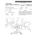
[0008] FIG. 1 is a perspective view of the invention;
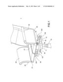
[0009] FIG. 2 is an exploded view of the invention;
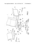
[0010] FIG. 3 is a front view of the invention;
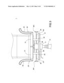
[0011] FIG. 4 is a schematic view showing how the seat width is adjusted;
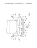
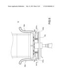
[0012] FIG. 5 is a front view of the second embodiment of the invention;
[0013] FIG. 6 is a schematic view of the second embodiment, which shows how the seat width is adjusted;
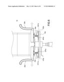
[0014] FIG. 7 is a front view of the third embodiment of the invention; and
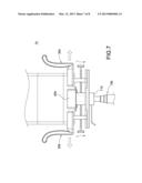
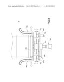
[0015] FIG. 8 is a front view of the fourth embodiment of the invention.
DETAILED DESCRIPTION OF THE INVENTION
[0016] Please refer to FIGS. 1-3. The chair 1 of the invention includes a stand 10, a first seat 20 and a second seat 30.
[0017] The stand includes a mount 11 and a supporting bar 12 connected to the mount 11. In this embodiment, the mount 11 is provided with a receiving hole 110 and a cuboid.
[0018] The first seat 20 is slidably connected to a side of the supporting bar 12. The first seat 20 includes a first cushion 21 and a first armrest 22 vertically extending therefrom. The first seat 20 further includes a first post 24 and a first adjusting rod 25. The first post 24 is fixed under the first cushion 21. The supporting bar 12 is provided with a first trough 121 for slidably engaging with the first post 24. The first post 24 is formed with a first threaded hole 240.
[0019] The second seat 30 is slidably connected to the other side of the supporting bar 12 to associate with the first seat 20. The second seat 30 includes a second cushion 31 and a second armrest 32 vertically extending therefrom. The second seat 30 further includes a second post 34 and a second adjusting rod 35. The second post 34 is fixed under the second cushion 31. The supporting bar 12 is provided with a second trough 122 for slidably engaging with the second post 34. The second post 34 is formed with a second threaded hole 340. The seats 20, can be horizontally slid to adjust their distance.
[0020] In this embodiment, each of the first adjusting rod 25 and the second adjusting rod 35 is a bolt and is provided with a knob 251, 351 for being held to rotate. Besides, a first fastener 26 and a second fastener 36 is received in the receiving hole 110 of the mount 11. The first adjusting rod 25 passes through the first threaded hole 240 and rotatably fixed in the first fastener 26. Similarly, the second adjusting rod 35 passes through the second threaded hole 340 and rotatably fixed in the second fastener 36.
[0021] Please refer to FIG. 4. The distance between the first seat 20 and second seat 30 can be adjusted by sliding themselves. Also, the armrests 22, 32 will move with the seats 20, 30 to abut against the user. To adjust the distance, the knobs 251, 351 are rotated to make the adjusting rods 25, 35 escape from the fasteners 26, 36 and then the posts 24, 34 with the cushions 21, 31 can be slid on the troughs 121, 122 to vary the position of the seats 20, 30.
[0022] It should be noted that the first seat 20 and second seat 30 can be independently or simultaneously moved to adjust their distance.
[0023] Please refer to FIGS. 5 and 6, which show the second embodiment of the invention. The second embodiment differs from the above embodiment by the positioning structure of the seats 20a, 30a of the chair 1a. In this embodiment, the first post 24a of the first seat 20a is pivotally disposed with a first link 241a. The first trough 121a of the supporting bar 12a is formed with a plurality of first perforations 1211a. The first seat 20a is adjustably fixed on the supporting bar 12a by inserting the first link 241a into one of the first perforations 1211a.
[0024] Similarly, the second post 34a of the second seat 30a is pivotally disposed with a second link 341a. The second trough 122a of the supporting bar 12a is formed with a plurality of second perforations 1221a. The second seat 30a is adjustably fixed on the supporting bar 12a by inserting the second link 341a into one of the second perforations 1221a.
[0025] Please refer to FIG. 6. To adjust the distance between the seats 20a, 30a, the links 241a, 341a have to be pressed to make them escape from the perforations 1211a, 1221a. As a result, the posts 24a, 34a can be slid in the troughs 121a, 122a. The seats 20a, 30a will be fixed by inserting the links 241a, 341 into the perforations 1211a, 1221a.
[0026] FIG. 7 shows the third embodiment of the invention. In this embodiment, the chair 1b further includes a middle seat 40b between the first seat 20b and the second seat 30b. The middle seat 40b is fastened to the mount 11b of the stand 10b.
[0027] FIG. 8 shows the fourth embodiment of the invention. In this embodiment, the chair 1c includes a stand 10c, a middle seat 20c, a first seat 30c and a second seat 40c.
[0028] The stand 10c includes a mount 11c and a supporting bar 12c. The middle seat 20c is fixed on the mount 11c. The first seat 30c associates with the middle seat 20c and on a side of the supporting bar 12c. The second seat 40c is corresponding to the first seat 30c and on the other side of the supporting bar 12c.
[0029] The first seat 30c is fixed to the bottom of the middle seat 20c and has a first post 33c and a first adjusting rod 34c. The first adjusting rod 34c passes through the first post 33c and is fixed to the mount 11c. The first post 33c is fixed to the bottom of the bottom of the first seat 30c. The supporting bar 12c is formed with a first trough 121c for slidably engaging with the first post 33c.
[0030] Similarly, the second seat 40c is fixed to the bottom of the middle seat 20c and has a second post 43c and a second adjusting rod 44c. The second adjusting rod 44c passes through the second post 43c and is fixed to the mount 11c. The second post 43c is fixed to the bottom of the bottom of the second seat 40c. The supporting bar 12c is formed with a second trough 122c for slidably engaging with the second post 43c.
[0031] It will be appreciated by persons skilled in the art that the above embodiments have been described by way of example only and not in any limitative sense, and that various alterations and modifications are possible without departure from the scope of the invention as defined by the appended claims.
User Contributions:
Comment about this patent or add new information about this topic:
| People who visited this patent also read: | |
| Patent application number | Title |
|---|---|
| 20210285206 | INSULATABLE, INSULATIVE FRAMEWORK APPARATUS AND METHODS OF MAKING AND USING SAME |
| 20210285205 | BUILDING STRUCTURE, BUILDING, AND BUILDING METHOD |
| 20210285204 | Frame Structure for a Floating Installation |
| 20210285203 | SYSTEMS, APPARATUS, AND METHODS FOR MAINTENANCE OF STORMWATER MANAGEMENT SYSTEMS |
| 20210285202 | FLOOR DRAIN |
Images included with this patent application:
 |  |
 |  |
 |  |
 |  |
 |
| Similar patent applications: | |
| Date | Title |
|---|---|
| 2013-10-31 | Infant to adult adjustable car seat |
| 2012-11-01 | Adjustable chair |
| 2012-11-22 | Adjustable head rest |
| 2013-05-16 | Adjustable telescoping arm |
| 2010-03-18 | Adjustable workstation |
| New patent applications in this class: | |
| Date | Title |
|---|---|
| 2018-01-25 | Adjustable seat assembly with driving modes |
| 2016-12-29 | Back support |
| 2016-06-16 | Bicycle saddle |
| 2016-05-05 | Seat for vehicles |
| 2016-03-31 | Independent cushion extension with optimized leg-splay angle |
| New patent applications from these inventors: | |
| Date | Title |
|---|---|
| 2015-03-05 | Chair with seat of adjustable length |
| Top Inventors for class "Chairs and seats" | |
| Rank | Inventor's name |
|---|---|
| 1 | Johnathan Andrew Line |
| 2 | Larry P. Lapointe |
| 3 | Yukifumi Yamada |
| 4 | John W. Jaranson |
| 5 | Erwin Haller |