Patent application title: METHOD AND DEVICE FOR DIAGNOSING AN ERROR IN AN EXHAUST GAS RECIRCULATION SYSTEM
Inventors:
Daniel Kuhn (Walddorfhaeslach, DE)
Andras Montvay (Markgroeningen, DE)
IPC8 Class: AF01N1100FI
USPC Class:
60277
Class name: Power plants internal combustion engine with treatment or handling of exhaust gas having sensor or indicator of malfunction, unsafeness, or disarray of treater (e.g., fusible link, etc.)
Publication date: 2013-03-21
Patent application number: 20130067893
Abstract:
In a method for determining a faulty exhaust gas recirculation line in an
exhaust gas recirculation system of an internal combustion engine having
multiple exhaust gas recirculation lines, a quantity of gas indicated by
a specified exhaust gas recirculation rate is provided proportionately
via the exhaust gas recirculation lines in accordance with an exhaust gas
recirculation apportioning ratio, and the method further includes:
testing in order to recognize an error in the exhaust gas recirculation
system; when the error is recognized, performing a modification of the
exhaust gas recirculation apportioning ratio and renewed testing of the
exhaust gas recirculation system; and determination of the faulty exhaust
gas recirculation line as a function of a result of the renewed testing.Claims:
1. A method for determining a faulty exhaust gas recirculation line in an
exhaust gas recirculation system of an internal combustion engine having
a plurality of exhaust gas recirculation lines, wherein a quantity of gas
indicated by a specified exhaust gas recirculation rate is provided
proportionately via the exhaust gas recirculation line in accordance with
an exhaust gas recirculation apportioning ratio, the method comprising:
testing the exhaust gas recirculation system in order to recognize an
error in the exhaust gas recirculation system; when the error is
recognized, performing (i) a modification of the exhaust gas
recirculation apportioning ratio and (ii) a renewed testing of the
exhaust gas recirculation system; and determining a faulty exhaust gas
recirculation line as a function of a result of the renewed testing of
the exhaust gas recirculation system.
2. The method as recited in claim 1, wherein, when the error is recognized, the exhaust gas recirculation apportioning ratio is modified in such a way that the quantity of exhaust gas to be recirculated is recirculated completely through only one of the exhaust gas recirculation lines.
3. The method as recited in claim 1, wherein, when the error is recognized, the quantity of recirculated exhaust gas through one of the exhaust gas recirculation lines is maintained while the recirculation of exhaust gas through the remaining exhaust gas recirculation lines is stopped.
4. The method as recited in claim 3, wherein a target air quantity is adapted in accordance with the maintained quantity of the exhaust gas recirculated through the one of the exhaust gas recirculation lines in order to maintain the exhaust gas recirculation rate.
5. The method as recited in claim 2, wherein the exhaust gas recirculation line through which exhaust gas is exclusively recirculated after the error is recognized is selected as a function of the exhaust gas recirculation apportioning ratio existing before the recognition of the error.
6. The method as recited in claim 5, wherein the selection of the exhaust gas recirculation line through which exhaust gas is exclusively recirculated is carried out as a function of a result of at least one threshold value comparison with at least one threshold value.
7. The method as recited in claim 6, wherein the at least one threshold value is one of fixed or selected as a function of an operating point of the internal combustion engine.
8. The method as recited in claim 6, wherein two threshold values are provided in order to define a range of the exhaust gas recirculation apportioning ratio in which the quantity of exhaust gas to be recirculated is provided through a plurality of exhaust gas recirculation lines after the recognition of the error.
9. The method as recited in claim 2, wherein the testing of the exhaust gas recirculation system is carried out in order to recognize a flow error of the exhaust gas recirculation system.
10. A device for determining a faulty exhaust gas recirculation line in an exhaust gas recirculation system of an internal combustion engine having a plurality of exhaust gas recirculation lines, wherein a quantity of gas indicated by a specified exhaust gas recirculation rate is provided proportionately via the exhaust gas recirculation line in accordance with an exhaust gas recirculation apportioning ratio, the device comprising: means for testing the exhaust gas recirculation system in order to recognize an error in the exhaust gas recirculation system; means for performing, when the error is recognized, the following: (i) a modification of the exhaust gas recirculation apportioning ratio and (ii) a renewed testing of the exhaust gas recirculation system; and means for determining a faulty exhaust gas recirculation line as a function of a result of the renewed testing of the exhaust gas recirculation system.
11. A non-transitory computer-readable data storage medium storing a computer program having program codes which, when executed on a computer, performs a method for determining a faulty exhaust gas recirculation line in an exhaust gas recirculation system of an internal combustion engine having a plurality of exhaust gas recirculation lines, wherein a quantity of gas indicated by a specified exhaust gas recirculation rate is provided proportionately via the exhaust gas recirculation line in accordance with an exhaust gas recirculation apportioning ratio, the method comprising: testing the exhaust gas recirculation system in order to recognize an error in the exhaust gas recirculation system; when the error is recognized, performing (i) a modification of the exhaust gas recirculation apportioning ratio and (ii) a renewed testing of the exhaust gas recirculation system; and determining a faulty exhaust gas recirculation line as a function of a result of the renewed testing of the exhaust gas recirculation system.
Description:
BACKGROUND OF THE INVENTION
[0001] 1. Field of the Invention
[0002] The present invention relates to internal combustion engines having exhaust gas recirculation, in particular to internal combustion engines having a plurality of exhaust gas recirculation lines, such as a high-pressure exhaust gas recirculation line and a low-pressure exhaust gas recirculation line, and the present invention also relates to methods for recognizing a type of error in such an exhaust gas recirculation system.
[0003] 2. Description of the Related Art
[0004] In internal combustion engines having exhaust gas recirculation, current legislation requires the recognition of the type of error in the exhaust gas recirculation system. In particular, it is to be recognized when the actual exhaust gas recirculation rate is too high or too low relative to the exhaust gas recirculation rate that is to be set, because this affects the emissions of the internal combustion engine. In today's engine systems, which have a high-pressure exhaust gas recirculation system, the type of error can be detected through suitable observation of sensors that are present, such as the hot-film air mass sensor for measuring the mass flow of the supplied fresh air, the intake pipe sensor for measuring an intake pipe pressure, and the like, and observation of the reaction of the exhaust gas recirculation regulating system. Modern engine systems have exhaust gas recirculation systems having two exhaust gas recirculation lines. A high-pressure exhaust gas recirculation line connects the exhaust gas evacuation segment to an intake pipe at a position upstream from a turbine of a charge device such as an exhaust gas turbocharger, while a low-pressure exhaust gas recirculation line connects the exhaust gas evacuation segment to the air supply system at a position downstream from the turbine, at a region before a compressor of the charge device. A transfer of the above-described method for recognizing the type of error in the exhaust gas recirculation system to such an exhaust gas recirculation system having two exhaust gas recirculation lines is not readily possible, especially without providing additional sensors. In particular, it is necessary, in addition to determining an error and the type of error in the exhaust gas recirculation system, also to find out in which of the exhaust gas recirculation lines the error has occurred.
BRIEF SUMMARY OF THE INVENTION
[0005] According to a first aspect of the present invention, a method is provided for determining a faulty exhaust gas recirculation line in an exhaust gas recirculation system having a plurality of exhaust gas recirculation lines in an internal combustion engine, an exhaust gas quantity indicated by a specified exhaust gas recirculation rate being provided proportionately via the exhaust gas recirculation lines, in accordance with an exhaust gas recirculation apportioning ratio. The method includes the following steps:
[0006] testing in order to recognize an error in the exhaust gas recirculation system;
[0007] when the error is recognized, modification of the exhaust gas recirculation apportioning ratio and renewed testing of the exhaust gas recirculation system;
[0008] determination of the faulty exhaust gas recirculation line as a function of a result of the renewed testing.
[0009] As a rule, errors are distinguished by recognizing different features or a resulting error pattern. Likewise, multi-stage diagnoses are known in which a first test yields a general suspicion of error, and in a second stage for example an intrusive test is carried out, or the system is referred to a workshop for further diagnosis.
[0010] As a reaction to a recognized error, up to now either the entire exhaust gas recirculation regulation is switched off, or, in the case of minor errors, the regulation is continued with acceptance of larger tolerances in the regulation.
[0011] For the case in which, in an exhaust gas recirculation system having a plurality of exhaust gas recirculation lines, the type of error can be recognized, in particular a throughput error, but it cannot be recognized in which of the exhaust gas recirculation lines the error has occurred, the above method provides modification of the apportioning of the exhaust gas recirculation to the exhaust gas recirculation lines when an error is recognized in the exhaust gas recirculation system. The location of the error can be inferred as a function of a result of a subsequent renewed testing of the exhaust gas recirculation system.
[0012] In an exhaust gas recirculation system having two exhaust gas recirculation lines, the apportioning of the exhaust gas recirculation takes place as specified by an exhaust gas recirculation apportioning ratio (AGR apportioning ratio, AGR fraction), such that given an AGR apportioning ratio of 0%, only a high-pressure exhaust gas recirculation line is used, and given an AGR apportioning ratio of 100% only a low-pressure exhaust gas recirculation line is used for the exhaust gas recirculation. This method is carried out after an error has been recognized in the exhaust gas recirculation system, indicating a high flow error, i.e. an excessive gas mass flow is flowing via the exhaust gas recirculation system, or a low flow error, i.e. a too-low gas mass flow is flowing via the exhaust gas recirculation system. Such an item of error information can be obtained from various items of sensor information, which however do not enable pinpointing, i.e. assignment of the error to one of the exhaust gas recirculation lines.
[0013] The above method has the advantage that in a simple manner an assignment of a recognized error to one of the exhaust gas recirculation lines in an exhaust gas recirculation system is possible. Because the operating point of the internal combustion engine is not impaired by the use of the method, i.e. no excitation oriented to the regulation target is realized in the system, it can be carried out almost entirely unnoticed by a driver of a motor vehicle operated with the internal combustion engine.
[0014] In addition, when the error is recognized the exhaust gas recirculation apportioning ratio can be modified in such a way that the quantity of exhaust gas to be recirculated is recirculated completely through only one of the exhaust gas lines, an assignment of the error to one of the exhaust gas recirculation lines (pinpointing) being possible on the basis of the type of error and the active exhaust gas recirculation line.
[0015] Alternatively, when the error is recognized the quantity of recirculated exhaust gas through one of the exhaust gas recirculation lines can be maintained, while the recirculation of exhaust gas through the other exhaust gas recirculation line or lines can be stopped.
[0016] It can be provided that in order to maintain the exhaust gas recirculation rate the target air quantity is adapted so as to correspond to the quantity of the exhaust gas recirculated through the one of the exhaust gas recirculation lines.
[0017] In particular, the selection of the exhaust gas recirculation line through which exhaust gas is exclusively recirculated after recognition of the error can be made as a function of the exhaust gas recirculation apportioning ratio existing before the recognition of the error.
[0018] According to a specific embodiment, the selection of the exhaust gas recirculation line can be carried out as a function of the result of a threshold value comparison with one or more threshold values.
[0019] It can be provided that the threshold value is fixed, or is selected as a function of an operating point of the internal combustion engine.
[0020] Alternatively, two threshold values can be provided in order to define a range of the exhaust gas recirculation apportioning ratio, in which the exhaust gas quantity to be recirculated is provided through a plurality of exhaust gas lines even after the recognition of the error.
[0021] According to a specific embodiment, the testing can be carried out in order to recognize a flow error, in particular a high flow error or a low flow error, of the exhaust gas recirculation system.
[0022] According to a further aspect of the present invention, a device is provided for determining a faulty exhaust gas recirculation line in an exhaust gas recirculation system having a plurality of exhaust gas recirculation lines in an internal combustion engine, an exhaust gas quantity indicated by a specified exhaust gas recirculation rate being provided proportionately via the exhaust gas recirculation lines in accordance with an exhaust gas recirculation apportioning ratio. The device is fashioned:
[0023] to carry out a test in order to recognize an error in the exhaust gas recirculation system;
[0024] when the error is recognized, to modify the exhaust gas recirculation apportioning ratio and to carry out a renewed test of the exhaust gas recirculation system; and
[0025] to determine the faulty exhaust gas recirculation line as a function of a result of the renewed testing.
[0026] According to a further aspect of the present invention, an engine system is provided. The engine system includes:
[0027] an internal combustion engine;
[0028] an exhaust gas recirculation system having a plurality of exhaust gas recirculation lines between an air supply system and an exhaust gas evacuation segment; and
[0029] the above-described device.
[0030] According to a further aspect of the present invention, a computer program product is provided that contains a program code that carries out the above-described method when it is executed on a data processing device.
BRIEF DESCRIPTION OF THE DRAWINGS
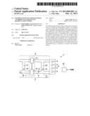
[0031] FIG. 1 shows a schematic representation of an engine system having an exhaust gas recirculation system having two exhaust gas recirculation lines.
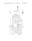
[0032] FIG. 2 shows a block diagram illustrating the carrying out of the method for error assignment.
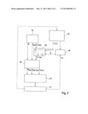
[0033] FIG. 3 shows a flow diagram illustrating the method for assigning a recognized error in the exhaust gas recirculation system.
DETAILED DESCRIPTION OF THE INVENTION
[0034] FIG. 1 shows an engine system 1 having an internal combustion engine 2. Internal combustion engine 2 can be fashioned as a diesel engine, a gasoline engine, or the like.
[0035] Air is supplied to internal combustion engine 2 via an air supply system 3. The air is mixed with fuel and is combusted in cylinders 4 of internal combustion engine 2. Combustion exhaust gas is carried away from cylinders 4 via an exhaust gas evacuation segment 6. The fuel can be supplied to internal combustion engine 2 directly by injection into cylinders 4 or via an intake pipe segment 5 of air supply system 3.
[0036] A charge device 7 is provided that can be realized for example as an exhaust gas turbocharger. Charge device 7 has a turbine 71 in exhaust gas evacuation segment 6, which can be driven through exhaust gas enthalpy of the combustion exhaust gas. Turbine 71 is coupled to a compressor 72 that is situated in air supply segment 3 and that suctions air from the surrounding environment and provides it, compressed to a charge pressure, in a charge pressure region 8 of air supply system 3. Charge pressure region 8 is a region situated immediately at the output side of compressor 72.
[0037] In addition, a throttle valve 9 is provided in air supply system 3. Intake pipe segment 5 is situated downstream from throttle valve 9, i.e. between throttle valve 9 and internal combustion engine 2. An exhaust gas recirculation system is provided that includes a first exhaust gas recirculation line 10, a so-called high-pressure exhaust gas recirculation line, and a second exhaust gas recirculation line 11, a so-called low-pressure exhaust gas recirculation line.
[0038] First exhaust gas recirculation line 10 connects a region of exhaust gas evacuation segment 6 between internal combustion engine 2 and turbine 71 of charge device 7 to intake pipe segment 5 of air supply system 3. In first exhaust gas recirculation line 10 there is provided a first exhaust gas feedback valve 12 that enables setting of the exhaust gas mass flow flowing through first exhaust gas recirculation line 10.
[0039] Second exhaust gas recirculation line 11 connects a downstream region of turbine 71 of charge device 7 to the inlet side of compressor 72. In second exhaust gas recirculation line 11 there is provided a second exhaust gas recirculation valve 13 in order to enable setting of a quantity of the exhaust gas recirculated via second exhaust gas recirculation line 11.
[0040] Exhaust gas recirculation lines 10, 11 can contain exhaust gas recirculation coolers (not shown) in order to lower the temperature of the recirculated exhaust gas so that the density and thus the overall mass of the recirculated exhaust gas can be increased.
[0041] Internal combustion engine 2 is operated by a control unit 15. For this purpose, via suitable sensors such as a hot-film air mass sensor 14, various pressure sensors, and the like, control unit 15 acquires operating states of engine system 1, and controls them by controlling actuators, such as throttle valve 9, of first and second exhaust gas recirculation valve 12, 13, injection valves (not shown) for setting the quantity of fuel to be injected, and the like, in order to operate internal combustion engine 2 in accordance with a specified torque FWM desired by the driver as an external specification.
[0042] In such an exhaust gas recirculation system, having two (or more than two) exhaust gas recirculation lines 10, 11, errors can occur, so that the exhaust gas recirculation system has to be monitored, because errors in the exhaust gas recirculation system, in particular errors in the setting of a specified exhaust gas recirculation rate, can make emissions worse. In particular, in the exhaust gas recirculation system errors can occur through which the set exhaust gas recirculation rate becomes too low relative to the desired exhaust gas recirculation rate, e.g. when there is blockage or sooting in exhaust gas recirculation lines 10, 11, or becomes too high, e.g. when there is a leak in the exhaust gas recirculation system, or when there is a faulty exhaust gas recirculation valve 12, 13.
[0043] Such a method first monitors the recirculated gas quantity through plausibilization of sensor or model values. In particular, an error can be recognized in the exhaust gas recirculation system by comparing an indication of the gas quantity flowing through the exhaust gas recirculation lines, determined using a mass flow balance of the quantity of supplied fresh air and of the volume suctioned into internal combustion engine 2 (as a function of rotational speed, number of cylinders, and displacement volume), to an indication of a quantity of gas flowing through the exhaust gas recirculation lines, this quantity being determined via the pressure ratio between a downstream and an upstream end of exhaust gas recirculation lines 10, 11 and a position of the relevant exhaust gas recirculation valve 12, 13. If the indications, obtained in different ways, of the quantity of gas flowing through the exhaust gas recirculation lines differ from one another, then it is possible to infer an error. As a function of the mathematical sign of the difference, a high flow error, i.e. a situation in which the quantity of gas supplied to the air supply system by the exhaust gas recirculation system is too high, or a low flow error, i.e. a situation in which the quantity of gas supplied to the air supply system by the exhaust gas recirculation system is too low, can be inferred.
[0044] In the following, the method for assigning a recognized error in the exhaust gas recirculation system to a relevant exhaust gas recirculation line 10, 11 is described on the basis of the block diagram shown in FIG. 2 and the flow diagram shown in FIG. 3.
[0045] The block diagram shown in FIG. 2 illustrates the functions for monitoring engine system 1 when an error is present in the exhaust gas recirculation system. The diagram of FIG. 2 schematically shows exhaust gas recirculation system 21, having exhaust gas recirculation valves 12, 13, which can be set according to target specifications by exhaust gas recirculation regulator 22.
[0046] Exhaust gas recirculation system 21 is monitored by a monitoring block 23, for example in the manner described above, in order to determine the presence of an error in exhaust gas recirculation system 21. A target value block 27 specifies target values for the current operating state relating to exhaust gas recirculation system 21. These target values are the air mass flow {dot over (m)} of the fresh air supplied to internal combustion engine 2, an exhaust gas recirculation rate rAGR, and an exhaust gas recirculation apportioning ratio rLPFRC (AGR apportioning ratio). Exhaust gas recirculation rate rAGR indicates in what portion combustion exhaust gas is to be fed into the air mass flow supplied to internal combustion engine 2. AGR apportioning ratio rLPFRC indicates the contributions that each of the exhaust gas recirculation lines 10, 11 are supposed to provide. For example, an AGR apportioning ratio rLPFRC of 50% indicates that the quantity of recirculated exhaust gas through the two exhaust gas recirculation lines 10, 11 should be provided in equal portions.
[0047] An AGR apportioning ratio rLPFRC of 100%, in contrast, indicates that the quantity of recirculated exhaust gas is to be provided completely via second exhaust gas recirculation line 11, while an AGR apportioning ratio rLPFRC of 0% indicates that the quantity of recirculated exhaust gas is to be supplied to the fresh air mass flow completely through first exhaust gas recirculation line 10.
[0048] A threshold value block 24 is provided to which AGR apportioning ratio rLPFRC, generated by target value block 27 according to an exhaust gas recirculation strategy, is supplied, and that is activated as soon as monitoring block 23 has recognized an error. Threshold value block 24 provides a diagnostic apportioning ratio rLPNeu according to which exhaust gas recirculation valves 12, 13 are to be set in order to permit a more precise diagnosis of the recognized error. From the diagnostic apportioning ratio rLPNeu, the air mass flow {dot over (m)} that is to be provided, and the exhaust gas recirculation rate rAGR, in a limiting block 25 a limiting air mass flow {dot over (m)}neu and a limiting exhaust gas recirculation rate rAGR--neu are determined and are supplied to exhaust gas recirculation regulator 22. In addition, diagnostic apportioning ratio rLP--neu is supplied to the limiting block in order there to apply possible component protective functions to diagnostic apportioning ratio rLP--neu.
[0049] Limiting block 25 modifies the supplied mass flow, exhaust gas recirculation rate rAGR, and, as needed, diagnostic apportioning ratio rLP--.sub.Neu in order to carry out a component protective function or similar functions. Limited air mass flow {dot over (m)}neu, limited exhaust gas recirculation rate rAGR--neu, and limited diagnostic apportioning ratio rLPlim are supplied to exhaust gas recirculation regulator 22, which correspondingly sets exhaust gas recirculation valves 12, 13. Threshold value block 24 sets either 0% or 100% as monitoring apportioning ratio rLP--neu, as a function of whether AGR apportioning ratio rLPFRC is above or below a threshold value S provided by a selection threshold value block 26.
[0050] As indicated in the flow diagram of FIG. 3, the monitoring for an error takes place in a querying step S1. If an error is recognized in exhaust gas recirculation system 21 (alternative: yes), then threshold value block 24 is activated and a jump takes place to step S2; otherwise (alternative: no) the query of step S1 is repeated.
[0051] In the query in step S2, it is now checked whether AGR apportioning ratio rLPFRC is above a specified threshold value S. If this is the case (alternative: yes), then 100% is assumed as monitoring apportioning ratio rLP--neu (step S3); i.e., exhaust gas recirculation rate rAGR is provided completely through second exhaust gas recirculation line 11. Otherwise (alternative: no), 0% is provided as monitoring apportioning ratio rLP--neu; i.e., exhaust gas recirculation rate rAGR is provided only via first exhaust gas recirculation line 10 (step S4).
[0052] Threshold value S can be fixedly specified, or can also be defined as a function of parameters that describe the operating point of internal combustion engine 2, such as a rotational speed indication or a load indication. In particular, threshold value S is applied in such a way that when a changeover takes place to an exhaust gas recirculation through only one of exhaust gas recirculation lines 10, 11, the variant is selected that has the lowest additional pollutant emissions.
[0053] If, in step S3, monitoring apportioning ratio rLP--.sub.NEU was set to 100%, then in a following step S5 the error monitoring carried out in step S1 is carried out again, and the location of the error in exhaust gas recirculation system 21 is inferred as a function of a renewed determination of the error recognized in step S1.
[0054] If in step S5 a so-called high flow error is recognized, i.e. the gas quantity conducted through exhaust gas recirculation system 21 exceeds the desired gas quantity, then in step S6 an error in first exhaust gas recirculation line 10 can be inferred. Otherwise, a jump takes place to step S7, in which it is checked whether the recognized type of error corresponds to a low flow error. A low flow error corresponds to an error in which the exhaust gas quantity supplied to air supply system 3 is lower than the desired exhaust gas quantity. In this case, an error in second exhaust gas recirculation line 11 can be inferred (step S8). If the method detects only the error types high flow error and low flow error, then the query in step S7 can be omitted, and, using a method of exclusion, in the absence of a high flow error it can be inferred that a low flow error must be present.
[0055] If, in step S4, monitoring apportioning ratio rLPneu was set to 0%, then in a following step S9 the error monitoring carried out in step S1 is carried out again, and the location of the error in exhaust gas recirculation system 21 is inferred as a function of a renewed determination of the error recognized in step S1.
[0056] If, in step S9, a so-called high flow error is recognized (alternative: yes), i.e. the quantity of gas conducted through exhaust gas recirculation system 21 exceeds the desired quantity of gas, then in step S10 an error in second exhaust gas recirculation line 11 can be inferred. Otherwise (alternative: no), in step S9 a jump takes place to step S11, in which it is checked whether instead a low flow error is present. If a low flow error is present (alternative: yes), then in step S12 an error in first exhaust gas recirculation line 10 is inferred.
[0057] Otherwise (alternative: no), i.e. in the case in which neither a high flow error nor a low flow error is present, in step S13 it is determined that an assignment of an error to one of exhaust gas recirculation lines 10, 11 cannot be carried out.
[0058] If the method detects only the error types high flow error and low flow error, then the query in step S11 can be omitted, and, using an exclusion method, in the absence of a high flow error it can be inferred that a low flow error must be present.
[0059] In an alternative specific embodiment, in threshold value block 24 it can be provided that, instead of adapting the monitoring apportioning ratio rLP--neu to 0 or 100%, it is provided that when AGR apportioning ratio rLPFRC is above specified threshold value S, the exhaust gas recirculation is carried out only using second exhaust gas recirculation line 11, according to the corresponding specified AGR apportioning ratio rLPFRC, while first exhaust gas recirculation line 10 is completely closed. If AGR apportioning ratio rLPFRC is smaller than threshold value S, then first exhaust gas recirculation line 10 is controlled in accordance with AGR apportioning ratio rLPFRC and second exhaust gas recirculation line 11 is completely closed. In this way, exhaust gas recirculation rate rAGR is reduced. In order to be able to further carry out the method in as emissions-neutral a fashion as possible, air mass target value rDESVAL should also be correspondingly adapted as follows:
rDESVAL--neu=rDESVAL×rLPFRC, if rLPFRC>S and
rDESVAL--neu=rDESVAL×(1-rLPFRC), if rLPFRC<S.
[0060] In this way, the set exhaust gas recirculation rate remains constant.
[0061] Through selection threshold value block 26, instead of a specified threshold value S it is also possible for two selection threshold values Sa, Sb to be provided. The definition of monitoring apportioning ratio rLP--neu is then as follows:
rLP--neu=0 if rLPFRC<Sa
rLP--neu=rLPFRC-Sa)/(Sb-Sa) if Sa≦rLPFRC≦Sb
rLP--neu=100 if rLPFRC>Sb.
[0062] If threshold values Sa and Sb are close to each other, there results an exhaust gas recirculation operation using only one of exhaust gas recirculation lines 10, 11 with adequate frequency.
[0063] The above-described method can usefully also be expanded to include the additional recognition of errors in air supply system 3, such as errors in hot-film air mass sensor 14 and errors in the charge pressure.
User Contributions:
Comment about this patent or add new information about this topic:
Images included with this patent application:
 |  |
 |  |
| Similar patent applications: | |
| Date | Title |
|---|---|
| 2014-01-09 | Method and device for energy conversion |
| 2010-12-09 | Apparatus and method for diagnosing catalyst deterioration |
| 2013-03-21 | Bleed air duct joint insulation means |
| 2011-02-10 | Jet engine protection system |
| 2011-09-29 | Device for reforming a voc gas |
| New patent applications in this class: | |
| Date | Title |
|---|---|
| 2018-01-25 | Method and system of urea solution level measurement adjustment, display and heater operation |
| 2016-06-23 | Diagnostic system for internal combustion engine |
| 2016-03-10 | Abnormality diagnosis system of air-fuel ratio sensor |
| 2016-03-10 | Abnormality diagnostic device for a particulate filter |
| 2016-02-11 | Diagnosing system for reductant dosing system |
| New patent applications from these inventors: | |
| Date | Title |
|---|---|
| 2016-06-09 | Method and apparatus for furnishing a filtered air system state variable in a control unit of an internal combustion engine |
| 2013-10-17 | Method and device for monitoring errors in an exhaust gas recirculation system |
| 2013-03-28 | Error cause detection or narrowing down of errors with the aid of error patterns in the air system |
| 2013-03-07 | Use of an estimated volumetric efficiency factor for error monitoring in the air system |
| Top Inventors for class "Power plants" | |
| Rank | Inventor's name |
|---|---|
| 1 | Gabriel L. Suciu |
| 2 | Patrick Benedict Melton |
| 3 | Eugene V. Gonze |
| 4 | Thomas Edward Johnson |
| 5 | Frederick M. Schwarz |