Patent application title: BELLOWS BACKUP CHAMBER
Inventors:
Timothy S. Roman (Minnetonka, MN, US)
Timothy S. Roman (Minnetonka, MN, US)
Kurt R. Sjodin (Cedar, MN, US)
Adam L. Kalthoff (Albany, MN, US)
IPC8 Class: AF04B5300FI
USPC Class:
417437
Class name: Pumps expansible chamber type
Publication date: 2013-02-14
Patent application number: 20130039788
Abstract:
The pump (10) prevents fluid leaks when a bellows (12) ruptures in a pump
incorporating a flexible bellows (12) as a primary seal and prevents
fluid from leaking out of a pump (10) or the pump (10) ingesting air in
the event of a bellows rupture. This is done by adding an additional seal
(22) after the bellows and a large volume backup chamber 24.Claims:
1. In a reciprocating piston pump having a bellows vent, a housing, a
flexible bellows seal around a shaft slideable in said housing in a low
pressure inlet chamber to create an air tight non-sliding seal, the
improvement comprising: a seal in said housing slideably sealing said
shaft and restricting leakage due to bellows seal failure which enters
the area formed between said shaft and said bellows seal; and a backup
chamber connected to said bellows vent.Description:
TECHNICAL FIELD
[0001] This application claims the benefit of U.S. Application Ser. No. 61/329,651, filed Apr. 30, 2010, the contents of which are hereby incorporated by reference.
BACKGROUND ART
[0002] In a typical reciprocating piston pump such as that shown in FIGS. 1 and 2, there is a seal that separates the high pressure working fluid from the atmosphere surrounding the pump. Even in perfect condition, these seals can weep a small amount of fluid each cycle and this can be detrimental to seal life. The fluid can solidify or crystallize and be pulled back into the seal, shortening the seal life. Historically one way to deal with this small amount of leakage has been to use a flexible bellows seal, which creates a pump without an exposed sliding seal. In such designs, the inlet of the pump is routed past the high pressure seal and the resulting low pressure inlet chamber is sealed by the bellows which creates an air tight non-sliding seal.
[0003] As the pump reciprocates, the bellows changes volume and thus the side of the bellows not contacting the working fluid is usually vented to the atmosphere to prevent pressure from building up. The problem with this basic layout is that when the bellows fails as a result of various conditions including fatigue, over-pressurization, or excessive speed, it can cause a substantial exterior leak. This is especially true if there is a positive pressure in the inlet chamber. This does not happen with a normal sliding seal which usually fails in a very slow predictable fashion, versus a sudden rupture.
DISCLOSURE OF THE INVENTION
[0004] It is an object of this invention to prevent fluid leaks when a bellows ruptures in a pump incorporating a flexible bellows as a primary seal.
[0005] The instant invention prevents fluid from leaking out of a pump or the pump ingesting air in the event of a bellows rupture. Ideally, this allows the pump to continue operating for a period of time until it is convenient to shut down the pump and replace the bellows seal.
[0006] The instant invention rectifies the sudden rupture failure mode of the bellows by adding an additional seal after the bellows and a large volume backup chamber as shown in FIG. 3. The purpose of the seal and backup chamber is to contain the working fluid after the bellows ruptures for a finite amount of time. It also keeps the system sealed to prevent the pump from ingesting air and thus allowing the pump to continue running
[0007] The backup seal above the bellows does not normally see the working fluid, which can be abrasive. This allows the seal to experience very little wear until the bellows fails, at which point it must start sealing against the working fluid. The chamber is sized such that the change in volume created by the bellows being compressed during normal operation does not cause an excessive swing in pressure.
[0008] These and other objects and advantages of the invention will appear more fully from the following description made in conjunction with the accompanying drawings wherein like reference characters refer to the same or similar parts throughout the several views.
BRIEF DESCRIPTION OF DRAWINGS
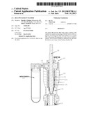
[0009] FIG. 1 is a cross-section of a prior art bellows pump showing the inlet port.
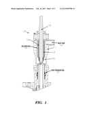
[0010] FIG. 2 is a cross-section of a prior art bellows pump showing the bellows vent.
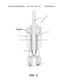
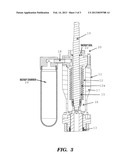
[0011] FIG. 3 is a cross-section of the bellows pump of the instant invention along a cross-section similar to that of FIG. 2.
BEST MODE FOR CARRYING OUT THE INVENTION
[0012] In a known reciprocating piston pump 10 shown in FIGS. 1 and 2, one way to deal with leakage has been to use a flexible bellows seal 12, which creates a pump 10 without an exposed sliding seal on shaft 19. In such designs, the inlet 14 of the pump is routed past the high pressure seal 13 and the resulting low pressure inlet chamber 16 in housing 17 is sealed by the bellows 12 which creates an air tight non-sliding seal.
[0013] As the pump 10 reciprocates, the bellows 12 changes volume and thus the side 12a of the bellows 12 not contacting the working fluid (and forming an inner chamber 15) is usually vented to the atmosphere through bellows vent 18 to prevent pressure from building up.
[0014] The instant invention 20 shown in FIG. 3 prevents fluid from leaking out of a pump 10 or the pump 10 ingesting air in the event of a bellows 12 rupture. Ideally, this allows the pump to continue operating for a period of time until it is convenient to shut down the pump 10 and replace the bellows seal 12.
[0015] The instant invention rectifies the sudden rupture failure mode of the bellows 12 by adding an additional seal 22 after the bellows 12 and a large volume backup chamber 24 as shown in FIG. 3. The purpose of the seal 22 and backup chamber 24 is to contain the working fluid after the bellows 12 ruptures for a finite amount of time. It also keeps the system sealed to prevent the pump 10 from ingesting air and thus allowing the pump 10 to continue running.
[0016] The backup seal 22 above the bellows 12 does not normally see the working fluid, which can be abrasive. This allows the seal 22 to experience very little wear until the bellows 12 fails, at which point it must start sealing against the working fluid. The chamber 24 is sized such that the change in volume created by the bellows 12 being compressed during normal operation does not cause an excessive swing in pressure.
[0017] It is contemplated that various changes and modifications may be made to the bellows sealing system without departing from the spirit and scope of the invention as defined by the following claims.
User Contributions:
Comment about this patent or add new information about this topic:
| People who visited this patent also read: | |
| Patent application number | Title |
|---|---|
| 20130038300 | SWITCHING REGULATOR, CONTROL CIRCUIT THEREOF, CONTROL METHOD THEREOF AND ELECTRONIC APPARATUS |
| 20130038299 | NANO GENERATOR AND METHOD OF MANUFACTURING THE SAME |
| 20130038298 | CHARGE RECYCLING CIRCUIT |
| 20130038297 | BATTERY CHARGING CONTROL DEVICE AND METHOD OF IMPLEMENTING THE SAME |
| 20130038296 | System For Storing Electric Energy |
Images included with this patent application:
 |  |
 |  |
| Similar patent applications: | |
| Date | Title |
|---|---|
| 2014-01-02 | Axial pistons hydraulic pump able to function in one or the other rotating direction |
| New patent applications in this class: | |
| Date | Title |
|---|---|
| 2019-05-16 | Pump with segmented fluid end housing and in-line valve |
| 2016-07-14 | Pressurizing booster compressor |
| 2016-06-16 | Integrated high pressure pump with cylinder block |
| 2016-06-09 | Evacuated tube transport system |
| 2016-06-09 | Compressed air supplying device of a sewing machine |
| New patent applications from these inventors: | |
| Date | Title |
|---|---|
| 2021-10-07 | Pneumatic surge suppressor |
| 2021-07-01 | Bellows pressure relief valve |
| 2017-06-22 | Bellows anti-rotation construction |
| 2017-06-22 | Internal bellows bearing |
| 2017-06-22 | Bellows pressure relief valve |
| Top Inventors for class "Pumps" | |
| Rank | Inventor's name |
|---|---|
| 1 | Masaki Ota |
| 2 | Ken Suitou |
| 3 | Alex Horng |
| 4 | Yusuke Yamazaki |
| 5 | Lars Hoffmann Berthelsen |