Patent application title: NON-SLIP SOLE STRUCTURE
Inventors:
Ching-Nan Lee (Xianxi Township, TW)
IPC8 Class: AA43B1322FI
USPC Class:
36 25 R
Class name: Boots, shoes, and leggings soles
Publication date: 2013-02-14
Patent application number: 20130036633
Abstract:
A non-slip sole structure of anti-slip shoes used for stream trekking and
fishing is made of a material with a large coefficient of friction such
as unwoven fabric and having regular or irregular hollow grooves formed
at predetermined positions of the sole to match with corresponding bumps,
formed at the bottom of a shoe body. When the sole is combined with the
bottom of the shoe body, the bumps at the bottom of the shoe body bottom
are passed through the hollow grooves of the sole respectively and
slightly protruded and exposed to achieve a more secured embedded
positioning effect and provide an appropriate bending and extending
deformation margin to the sole to avoid a stripping problem effectively.
The bumps at the bottom of the shoe body are slightly protruded from the
sole surface to improve an anti-slip grip effect and avoid wearing out
the sole too quickly.Claims:
1. A non-slip sole structure, comprising: a sole, made of a material with
a large coefficient of friction; and a shoe body, having a bottom
securely combined to the sole, such that when a user steps or walks with
the shoe body on a ground, the sole and the ground obtain a better
friction to provide an anti-slip function; characterized in that the sole
comprises a plurality of hollow grooves formed at predetermined positions
of the sole respectively, and a plurality of corresponding bumps formed
at corresponding positions at the bottom of the shoe body respectively,
such that when the sole and the shoe body are combined, the bumps at the
bottom of the shoe body are passed through the hollow grooves of the sole
respectively and exposed to the outside, and the sole and the shoe body
are embedded and fixed with one another.
2. The non-slip sole structure of claim 1, wherein each of the bumps formed at the bottom of the shoe body bottom has a height slightly greater than the thickness of the sole, so that when the sole is combined to the bottom of the shoe body, the bumps are passed through the hollow grooves of the sole respectively and slightly protruded from a surface of the sole.
3. The non-slip sole structure of claim I, wherein the sole further includes a predetermined number of nails installed at a top surface of the sole, and an end of each nail is slightly protruded from the sole.
4. The non-slip sole structure of claim 1, wherein the sole and the shoe body are combined and adhered with each other by a glue, and the glue is extended to contact interfaces between the bumps and the hollow grooves, in addition to a contact surface between the sole and the bottom of the shoe body.
5. The non-slip sole structure of claim I. wherein the sole is integrated with the bottom of the shoe body during an injection molding process of the shoe body, so that the material for forming the shoe body is distributed to the preformed hollow grooves of the sole to form the bumps.
Description:
BACKGROUND OF THE INVENTION
[0001] 1. Field of the Invention
[0002] The present invention relates to a non-slip sole structure, and more particularly to the non-slip sole structure for shoes applied for stream trekking, rock fishing or fish catching to overcome the conventional structure having the drawbacks of easy stripping, poor anti-slip effect and high wear out rate, and the non-slip sole structure of the invention can improve the connection between a sole and a shoe body and provide a better anti-slip effect.
[0003] 2. Description of the Related Art
[0004] When conducting activities such as stream trekking, rock fishing or fish catching, people have safety concerns and may slip easily due to unstable equilibrium or mosses and algae formed on rocks under a stream or wave blocks at a seashore, and thus it is necessary to wear stream trekking shoes, barreled boots, rain boots, jumpsuit specified shoes or the like. In general, a special design of a non-slip sole structure of a sole is used to improve the friction when stepping on the rocks or wave blocks, so as to reduce the chance of slipping or falling accidentally.
[0005] In the design of special ,shoes of this sort, a sole is usually made of a material having a large coefficient of friction such as an unwoven fabric, and the sole is combined with a shoe body by adhering a glue, and a non-smooth surface of the material such as the unwoven fabric can provide a larger friction, so that when a user steps or walks on the slippery rocks or wave blocks, the shoes can provide an appropriate anti-slip effect.
[0006] However, the structural design of the aforementioned conventional shoes still have the following drawbacks
[0007] 1. The sole is made of unwoven fabrics and thus has a loosened structure and a poor durability, so that the sole may be worn out easily, although it can achieve the expected anti-slip effect.
[0008] 2. The sole is in a flat shape, and comes with a rough surface to achieve a larger friction and resistance for an appropriate anti-slip effect, but the anti-slip function varies with the environment, particularly if the rocks or wave blocks are large in size, the grip of the sole will be insufficient, and the anti-slip effect will be affected seriously.
[0009] 3. The sole and the shoe body are combined by a glue, so that the gluing position is at a planar contact interface between the sole and the shoe body only, but the sole is made of a relatively hard material. As a result, the glued sole cannot bear bending, and may he stripped easily after being worn for some time.
[0010] In other words, the conventional non-slip sole structure still have drawbacks that require feasible solutions and further improvements.
SUMMARY OF THE INVENTION
[0011] In view of the existing problems and drawbacks of the conventional non-slip sole structure, the inventor of the present invention based on years of experience in the related industry to conduct extensive researches and experiment, and finally developed a non-slip sole structure of the present invention to overcome the problems and drawbacks of the prior art.
[0012] Therefore, it is a primary objective of the invention to provide a non-slip sole structure that can achieve a more secured combination effect between a sole and a shoe body and avoid a stripping problem to extend the life of non-slip shoes.
[0013] Another objective of the present invention is to provide a non-slip sole structure that can improve the overall grip to enhance the stability of stepping and walking and provide a better wear, in addition to the more secured combination between the sole and the shoe body.
[0014] To achieve the foregoing objectives, the present invention provides a non-slip sole structure comprising a plurality of regular or irregular hollow grooves formed at predetermined positions of a sole respectively, and matched with a plurality of corresponding bumps formed at the bottom of a shoe body respectively, such that when the sole is combined with the bottom of the shoe body, the bumps at the bottom of the shoe body are passed through the hollow grooves of the sole respectively and slight protruded and exposed to the outside, so as to achieve a more secured embedded positioning effect and provides an appropriate bending and extending deformation margin to the sole to improve the stripping problem. Since the bumps at the bottom of the shoe body are slightly protruded from a surface of the sole, the anti-slip grip can be improved, and a quick worn-out of the sole can be avoided.
BRIEF DESCRIPTION OF THE DRAWINGS
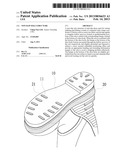
[0015] FIG. 1 is a perspective view of a preferred embodiment of the present invention;
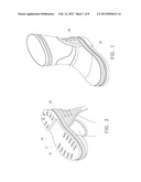
[0016] FIG. 2 is another perspective view of the preferred embodiment of the present invention;
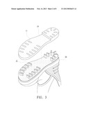
[0017] FIG. 3 is an exploded view of the preferred embodiment of the present invention;
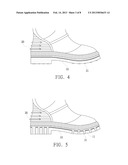
[0018] FIG. 4 is a schematic planar view of the preferred embodiment of the present invention;
[0019] FIG. 5 is a cross-sectional view of the preferred embodiment of the present invention;
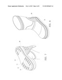
[0020] FIG. 6 is a perspective view of another preferred embodiment of the present invention;
[0021] FIG. 7 is another perspective view of the other preferred embodiment of the present invention;
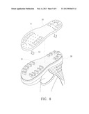
[0022] FIG. 8 is an exploded view of the other preferred embodiment of the present invention;
[0023] FIG. 9 is a schematic planar view of the other preferred embodiment of the present invention;
[0024] FIG. 10 is a cross-sectional view of the other preferred embodiment of the present invention;
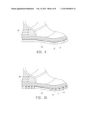
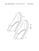
[0025] FIG. 11 is a schematic view of an application of a further preferred embodiment of the present invention; and
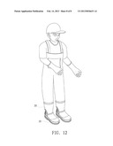
[0026] FIG. 12 is a schematic view of an application of another further preferred embodiment of the present invention.
DETAILED DESCRIPTION OF THE PREFERRED EMBODIMENTS
[0027] To make it easier for our examiner to understand the assembly, the technical characteristics and effects of the present invention, we use preferred embodiments with related drawings for the detailed description of the present invention as follows.
[0028] With reference to FIGS. I and 2 for perspective views, FIG. 3 for an exploded view, and FIGS. 4 and 5 for a schematic planar view and a cross-sectional view of a non-slip sole structure in accordance with a preferred embodiment of the present invention respectively, the non-slip sole structure comprises a sole 10 made of a material with a large coefficient of friction such as an unwoven fabric, and manufactured according to the shape of the bottom of a shoe body 20, a plurality of regular or irregular hollow grooves 11 formed at predetermined positions of the sole 10 respectively, and a plurality of bumps 21 formed at the bottom of the shoe body 20 and corresponding to the hollow grooves 11 respectively, and each of the bumps 21 has a height slightly greater than the thickness of the sole 10, such that when the sole 10 and the shoe body 20 are combined and adhered with each other by a glue, the bumps 21 at the bottom of the shoe body 20 are passed through the hollow grooves 11 of the sole 10 respectively to achieve an embedded positioning effect, and a distal surface of each bump 21 is slightly protruded and exposed to the outside. During the adhesive operation, the glue is applied to a contact surface between the sole 10 and the bottom of the shoe body 20, and also to a contact interface between the bumps 21 and the hollow grooves 11, or the sole 10 is formed first and then placed in a mold for performing an injection molding operation of the shoe body 20 to substitute the gluing method, but it is not the target of the present invention, so that will not be described here. The material for forming the shoe body 20 is circulated to the hollow grooves 11 of the sole 10 to form the bumps 21, so as to constitute the non-slip sole structure in accordance with a preferred embodiment of the present invention.
[0029] With the aforementioned structural design, the hollow grooves 11 of the sole 10 together with the bumps 21 of the shoe body 20 can achieve a multi-directional combination and a position-limit effect, and the design of the hollow grooves 11 can provide a better bending and extending deformation margin of the sole 10 for a bendable function to avoid a possible stripping problem effectively and extend the wearing life of the non-slip sole structure. In the other hand, the bumps 21 formed at the bottom of the shoe body 20 are slightly protruded from a surface of the sole 10, so that the grip and anti-slip effect can be enhanced to improve the anti-slip performance. When a user steps or walks on different terrains, the concern of being slipped accidentally can be avoided, and a large direct contact area with frictions between the sole 10 and different terrains is achieved, and a too-quick worn out of the sole 10 is avoided, so as to enhance the value of the overall practical application.
[0030] With reference to FIGS. 6 and 7 for schematic views, FIG. 8 for an exploded view, and FIGS. 9 and 10 for a schematic planar view and a cross-sectional view of a non-slip sole structure in accordance with another preferred embodiment of the present invention, the non-slip sole structure comprises a sole 10 made of a material such as an unwoven fabric, a plurality of regular or irregular hollow grooves 11 formed on the sole 10, a predetermined number of nails 12 formed at the top surface of the sole 10, wherein an end of each nail 12 is slightly protruded from the sole 10, and a plurality of corresponding bumps 21 formed at the bottom of the shoe body 20 bump 21, such that the sole 10 and the shoe body 20 can be combined and adhered by a glue, or the sole 10 is placed into a mold for integrally combining the shoe body 20 with the sole 10 when the shoe body 20 is processed by an injecting molding process, so as to constitute the non-slip sole structure of this preferred embodiment of the present invention. The hollow grooves 11 of the sole 10 together with the bumps 21 of the shoe body 20 not only provide a more secured embedded positioning effect, but also provide an appropriate bending and extending deformation margin to the sole 10 to overcome the stripping problem. In addition, the design having the bumps 21 formed at the bottom of the shoe body 20 and slightly protruded from a surface of the sole 10 and the nails 12 distributed on the sole 10 can improve the overall anti-slip grip and avoid a quick worn-out of the sole 10, so as to provide a high value of its practical application and extend the life of the sole 10.
[0031] With reference to FIGS. 11 and 12 for a non-slip sole structure of the present invention, the non-slip sole structure can be applied to stream trekking shoes, plastic shoes, or outdoor boots made of a general diving cloth, or even applied to a shoe body of a jumpsuit for a general fish catching operation with an anti-slip function, in addition to the aforementioned non-slip shoes such as the rain boots. The design having the hollow grooves 11 formed at the sole 10 together with bumps 21 formed at the bottom of the shoe body 20 can improve the connection between the sole 10 and the shoe body 20 and provide a better grip to overcome the problems and drawbacks of the conventional non-slip sole structure.
[0032] In summation, the non-slip sole structure of the present invention has the following advantages:
[0033] 1. Since the sole and the shoe body are adhered with each other by a glue, and the hollow grooves are formed on the sole and the corresponding bumps are formed at the bottom of the shoe body bottom, an embedded positioning effect is achieved to provide a more secured connection and prevent the stripping problem.
[0034] 2. The sole includes the regular or irregular hollow grooves to achieve a secured connection with the shoe body, and also provides a better bending and extending deformation margin to achieve a better durability for bending, so as to improve the comfort of using the non-slip sole structure.
[0035] 3. Since each of the bumps formed at the bottom of the shoe body has a height slightly greater than the thickness of the sole, the end surface of the bumps is slightly protruded from the sole surface, and the sole is in a full contact with the ground when the user steps or walks on the ground, so as to avoid a quick worn-out of the sole and improve the durability and lifespan of the sole.
[0036] 4. Since the bumps formed at the bottom of the shoe body are slightly protruded from the sole and disposed separately from one another at the bottom of the shoe body, therefore the bumps are not in a full contact with the ground when a user steps or walks on the ground. In addition, the material of the sole structure is made of a durable material with an excellent grip effect to improve the grip and anti-slip effect significantly, and prevent the user from falling or slipping accidentally, so as to provide a safe and practical application.
[0037] In summation of the description above, the non-slip sole structure of the present invention can be applied to specific shoes for stream trekking, rock fishing or fish catching operation, and the sole made of a material such as an unwoven fabric is used for achieving the non-slip function. The hollow grooves formed on the sole hollow together with the bumps formed at the bottom of the shoe body can provide a more secured connection and provide a better bending and extending deformation margin to improve the grip and durability of the sole structure and overcome the easy stripping problem of the conventional sole structure, so as to extend the lifespan of the sole and the safety of using the non-slip sole structure. Obviously, the invention herein enhances the performance than the conventional structure and further complies with the patent application requirements and is duly filed for patent application.
[0038] While the invention has been described by means of specific embodiments, numerous modifications and variations could be made thereto by those skilled in the art without departing from the scope and spirit of the invention set forth in the claims.
User Contributions:
Comment about this patent or add new information about this topic:
| People who visited this patent also read: | |
| Patent application number | Title |
|---|---|
| 20160080939 | AUTHENTIFICATION METHOD FOR A COMMUNICATION NETWORK |
| 20160080938 | METHOD FOR PROCESSING AUTHENTICATION, ELECTRONIC DEVICE AND SERVER FOR SUPPORTING THE SAME |
| 20160080937 | Mobile device-based keypad for enhanced security |
| 20160080936 | SYSTEMS AND METHODS FOR DEVICE BASED AUTHENTICATION |
| 20160080935 | CONTROLLER AND METHOD OF CONTROLLING MULTIPLE IDENTITIES OF A MOBILE DEVICE |
Images included with this patent application:
 |  |
 |  |
 |  |
 |  |
 |
| Similar patent applications: | |
| Date | Title |
|---|---|
| 2012-06-28 | Anti-slip spike structure |
| 2012-07-19 | Composite sole structure |
| 2012-05-03 | Interlocking shoe structure |
| 2010-03-04 | Footwear sole structure |
| 2010-10-14 | Thin-type spike intensifying structure |
| New patent applications in this class: | |
| Date | Title |
|---|---|
| 2016-12-29 | Footwear having auxetic structures with controlled properties |
| 2016-07-07 | Shoe with lattice structure |
| 2016-06-16 | Base for a ski boot and ski boot incorporating such a base |
| 2016-06-09 | Footwear with auxetic ground engaging members |
| 2016-06-09 | Footwear with flexible auxetic sole structure |
| Top Inventors for class "Boots, shoes, and leggings" | |
| Rank | Inventor's name |
|---|---|
| 1 | Frederick J. Dojan |
| 2 | Michael A. Aveni |
| 3 | Perry W. Auger |
| 4 | Sergio Cavaliere |
| 5 | Lee D. Peyton |