Patent application title: PICK-UP HEAD SYSTEM
Inventors:
Roger P. Vanderlinden (Burlington, CA)
Roger P. Vanderlinden (Burlington, CA)
IPC8 Class: AE01H108FI
USPC Class:
15246
Class name: Brushing, scrubbing, and general cleaning attachments
Publication date: 2013-01-24
Patent application number: 20130019429
Abstract:
A pick-up head system for use with a surface cleaning vehicle comprises a
housing, forward debris passage having a bottom opening, and a rearward
debris passage having a bottom opening. A divider separates the forward
debris passage and the rearward debris passage. A debris outlet supplies
a flow of high speed air a selected one of the forward debris passage and
the rearward debris passage. An air supply inlet is in the other one of
the forward debris passage and the rearward debris passage. A debris
passing opening between the forward debris passage and the rearward
debris passage permits the flow of air and debris from one to the other.
High speed air flows through the air supply inlet into the forward debris
passage and the rearward debris passage, as connected by the debris
passing opening, to thereby clean the surface, and egresses through the
debris outlet.Claims:
1. A pick-up head system for use with a surface cleaning vehicle, said
pick-up head system comprising: a housing extending side-to-side between
a first end and a second end and extending for-aft between a front end
and a back end, and having a bottom peripheral edge; wherein said bottom
peripheral edge is configured for interfacing said housing in
substantially sealed relation with a surface to be cleaned as the surface
cleaning vehicle moves along a surface to be cleaned; a forward debris
passage having a bottom opening along its length for permitting said flow
of high speed air to impact a surface to be cleaned substantially along
the entire length of said forward debris passage; a rearward debris
passage having a bottom opening along its length, and disposed rearwardly
with respect to said forward debris passage, for permitting said flow of
high speed air to impact a surface to be cleaned substantially along the
entire length of said rearward debris passage; a divider separating said
forward debris passage and said rearward debris passage; wherein said
divider has a bottom edge configured for interfacing said divider in
substantially sealed relation with a surface to be cleaned as the surface
cleaning vehicle moves along a surface to be cleaned; a debris outlet in
a selected one of said forward debris passage and said rearward debris
passage for permitting debris to egress said housing; an air supply inlet
in the other one of said forward debris passage and said rearward debris
passage for permitting a flow of air to enter said housing, for
connection to a source of high speed air flow; and, a debris passing
opening between said forward debris passage and said rearward debris
passage for permitting the flow of air and debris from one to the other;
and, wherein, in use, said air supply inlet supplies a flow of high speed
air to the selected one of said forward debris passage and said rearward
debris passage, and said air travels through the selected one of said
forward debris passage and said rearward debris passage, through said
debris passing opening to the other one of said forward debris passage
and said rearward debris passage, and egresses said housing through said
debris outlet.
2. The pick-up head system of claim 1, wherein said debris passing opening is disposed at one of said first end and said second end of said housing.
3. The pick-up head system of claim 1, wherein said forward debris passage extends from said first end to said second end of said housing.
4. The pick-up head system of claim 1, wherein said debris outlet is disposed in said forward debris passage of said housing.
5. The pick-up head system of claim 1, wherein said divider is selectively movable between a plurality of vertical positions to thereby permit the selection of the gap between the bottom edge of the dividing portion and the surface to be cleaned.
6. The pick-up head system of claim 1, further comprising an actuator for moving said divider between said plurality of vertical positions.
7. The pick-up head system of claim 1, wherein said housing is substantially "V"-shaped.
8. The pick-up head system of claim 1, wherein said debris outlet is generally centrally disposed is said housing between said first end and said second end.
Description:
RELATED APPLICATIONS
[0001] This application is a non-provisional application claiming priority from U.S. Provisional Patent Application Ser. No. 61/496,410 filed on Jun. 13, 2011, which is herein incorporated by reference.
FIELD OF THE INVENTION
[0002] The present invention relates to pick-up head systems for factory, sidewalk and street sweepers, and more particularly to such pick-up head systems that fully clean the surface to be cleaned.
BACKGROUND OF THE INVENTION
[0003] Prior art recirculating air type surface cleaning vehicles bleed-off a portion of air from the pressure side of the main fan and filter it to atmosphere, while returning the remainder of the air to the pick-up head. In many cases, air is returned to the pick-up head in the form of a full-width air blast that assists in cleaning the surface and traversing material across the pick-up head to the internal suction port. The fundamental drawback of this arrangement is that re-circulating air is introduced full-width in the pick-up head which includes directly adjacent the point of pick-up suction port which decreases negative pressure in that area and can affect pick-up.
[0004] It is an object of the present invention to provide a full-width dustless pick-up head system.
[0005] It is another object of the present invention to provide a pick-up head system that cleans virtually all debris from a surface being cleaned.
[0006] It is another object of the present invention to provide a pick-up head system that does not introduce re-circulated air adjacent the internal suction port.
[0007] It is another object of the present invention to provide a pick-up head system that does not allow for a decrease of air speed in the width of the housing.
[0008] It is another object of the present invention to provide a pick-up head system that does not allow for a decrease in negative pressure in the width of the housing.
SUMMARY OF THE INVENTION
[0009] In accordance with one aspect of the present invention there is disclosed a novel pick-up head system for use with a surface cleaning vehicle. The pick-up head system comprises a housing extending side-to-side between a first end and a second end and extending for-aft between a front end and a back end, and having a bottom peripheral edge; wherein the bottom peripheral edge is configured for interfacing the housing in substantially sealed relation with a surface to be cleaned as the surface cleaning vehicle moves along a surface to be cleaned; a forward debris passage having a bottom opening along its length for permitting the flow of high speed air to impact a surface to be cleaned substantially along the entire length of the forward debris passage; a rearward debris passage having a bottom opening along its length, and disposed rearwardly with respect to the forward debris passage, for permitting the flow of high speed air to impact a surface to be cleaned substantially along the entire length of the rearward debris passage; a divider separating the forward debris passage and the rearward debris passage; wherein the divider has a bottom edge configured for interfacing the divider in substantially sealed relation with a surface to be cleaned as the surface cleaning vehicle moves along a surface to be cleaned; a debris outlet in a selected one of the forward debris passage and the rearward debris passage for permitting debris to egress the housing; an air supply inlet in the other one of the forward debris passage and the rearward debris passage for permitting a flow of air to enter the housing, for connection to a source of high speed air flow; and a debris passing opening between the forward debris passage and the rearward debris passage for permitting the flow of air and debris from one to the other; and wherein, in use, the air supply inlet supplies a flow of high speed air to the selected one of the forward debris passage and the rearward debris passage, and the air travels through the selected one of the forward debris passage and the rearward debris passage, through the debris passing opening to the other one of the forward debris passage and the rearward debris passage, and egresses the housing through the debris outlet.
[0010] Other advantages, features and characteristics of the present invention, as well as methods of operation and functions of the related elements of the structure, and the combination of parts and economies of manufacture, will become more apparent upon consideration of the following detailed description and the appended claims with reference to the accompanying drawings, the latter of which is briefly described herein below.
BRIEF DESCRIPTION OF THE DRAWINGS
[0011] The novel features which are believed to be characteristic of the pick-up head system according to the present invention, as to its structure, organization, use and method of operation, together with further objectives and advantages thereof, will be better understood from the following drawings in which a presently preferred embodiment of the invention will now be illustrated by way of example. It is expressly understood, however, that the drawings are for the purpose of illustration and description only, and are not intended as a definition of the limits of the invention. In the accompanying drawings:
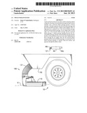
[0012] FIG. 1 is a side elevational view of the preferred embodiment of the dustless pick-up head system according to the present invention mounted on a surface cleaning vehicle;
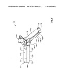
[0013] FIG. 2 is a front perspective view from above of the preferred embodiment dustless pick-up head system according to the present invention;
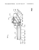
[0014] FIG. 3 is a side perspective view from underneath of the preferred embodiment dustless pick-up head system of FIG. 1;
[0015] FIG. 4 is a bottom plan view of the preferred embodiment dustless pick-up head system of FIG. 1;
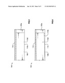
[0016] FIG. 5 is an enlarged sectional rear elevational view of the preferred embodiment dustless pick-up head system of FIG. 1, showing a movable dividing portion, in a lowered generally horizontal position; and
[0017] FIG. 6 is an enlarged sectional rear elevational view of the preferred embodiment dustless pick-up head system of FIG. 1, showing the movable dividing portion of FIG. 5 in the housing in a partially raised slanted position.
DETAILED DESCRIPTION OF THE PREFERRED EMBODIMENT
[0018] Reference will now be made to FIGS. 1 through 6, which show a preferred embodiment of the pick-up head system of the present invention, as indicated by general reference numeral 100. The pick-up head system 100 is for use with a surface cleaning vehicle 102 for removing dust (including fine particulate matter) and debris (including bottles, cans, leaves, dirt, and so on) from a surface to be cleaned 104.
[0019] The preferred embodiment pick-up head system 100 and comprises a substantially "V"-shaped housing 110 extending side-to-side between a first end 111 and a second end 112 and extending for-aft between a front end 115 and a back end 116. The housing 110 has bottom peripheral edge 109 configured for interfacing the housing 110 in substantially sealed relation with a surface to be cleaned 104 as the surface cleaning vehicle 102 moves along a surface to be cleaned 104. A forward debris passage 130 extends from the first end 111 to the second end 112 of the housing 110 and has a bottom opening 114 along its length for permitting the flow of high speed air to impact a surface to be cleaned 104 substantially along the entire length of the forward debris passage 130, from the first end 111 to the second end 112. A rearward debris passage 180 has a bottom opening along its length, and is disposed rearwardly with respect to the forward debris passage 130, for permitting the flow of high speed air to impact a surface to be cleaned 104 substantially along the entire length of the rearward debris passage 180.
[0020] A divider 110d separates the forward debris passage 130 and the rearward debris passage 180. The divider 110d has a bottom edge 110b configured for interfacing the divider 110d in substantially sealed relation with a surface to be cleaned 104 as the surface cleaning vehicle 102 moves along a surface to be cleaned 104. Furthermore, the divider 110d is selectively movable between a plurality of vertical positions to thereby permit the selection of the gap between the bottom edge 110b of the dividing portion 110b and the surface to be cleaned 104. The pick-up head system 100 further comprises an actuator (not specifically shown) for moving the divider 110d between the plurality of vertical positions.
[0021] A debris outlet 120 is disposed in a selected one of the forward debris passage 130 and the rearward debris passage 180 for permitting debris to egress the housing 110. In the preferred embodiment, as illustrated, the debris outlet 120 is disposed in the forward debris passage 130 of the housing 110. Further, the debris outlet 120 is generally centrally disposed in the housing 110 between the first end 111 and the second end 112.
[0022] An air supply inlet 181 is disposed in the other one of the forward debris passage 130 and the rearward debris passage 180 for permitting a flow of air to enter the housing 110, for connection to a source of high speed air flow, specifically the main fan 40 of the surface cleaning vehicle 102. In the preferred embodiment, as illustrated, the air supply inlet 181 is disposed in the forward debris passage 130.
[0023] There is also a debris passing opening between the forward debris passage 130 and the rearward debris passage 180 for permitting the flow of air and debris from one to the other. The debris passing opening is preferably disposed right at one, or both, of the first end 111 and the second end 112 of the housing 110. In the preferred embodiment, as illustrated, there is a first debris passing opening 182a disposed at the first end 111 of the housing 110 and a second debris passing 182b opening disposed at the second end 112 of the housing 110.
[0024] In use, the air supply inlet 181 supplies a flow of high speed air to the selected one of the forward debris passage 130 and the rearward debris passage 180. The air travels through the selected one of the forward debris passage 130 and the rearward debris passage 180, through the debris passing openings 182a, 182b to the forward debris passage 130 and the rearward debris passage 180, and egresses the housing 110 through the debris outlet 120.
[0025] As can be understood from the above description and from the accompanying drawings, the present invention provides a full-width dustless pick-up head system, that cleans virtually all debris from a surface being cleaned, that does not introduce air at the internal suction port, that does not allow for a decrease of air speed in the vacuum chamber, and wherein the on-going overall air blast in the pick-up head has more than one overall opportunity to impact the surface to be cleaned, all of which features are unknown in the prior art.
[0026] Other variations of the above principles will be apparent to those who are knowledgeable in the field of the invention, and such variations are considered to be within the scope of the present invention. Furthermore, other modifications and alterations may be used in the design and manufacture of the pick-up head system of the present invention without departing from the spirit and scope of the accompanying claims.
User Contributions:
Comment about this patent or add new information about this topic:
Images included with this patent application:
 |  |
 |  |
 |  |
| Similar patent applications: | |
| Date | Title |
|---|---|
| 2013-01-24 | Pick-up head system |
| 2009-07-30 | Vacuum hose storage system |
| 2009-07-30 | Vacuum hose storage system |
| 2011-02-24 | Vacuum hose storage system |
| New patent applications in this class: | |
| Date | Title |
|---|---|
| 2019-05-16 | A cleaning assembly |
| 2016-05-05 | Cleaning brush device for condenser |
| 2016-04-14 | Attachable teeth for cleaning hand tools |
| 2016-03-24 | Cleaning device for oil collecting brush |
| 2016-03-03 | Self-cleaning plumbing fixture |
| New patent applications from these inventors: | |
| Date | Title |
|---|---|
| 2015-01-29 | Apparatus for use as part of a surface cleaning vehicle and for use as part of a sander-salter vehicle |
| 2015-01-08 | High efficiency dust controlling gutter broom apparatus |
| 2014-08-07 | Gutter broom and gutter broom system |
| 2013-12-19 | Pick-up head system |
| 2013-07-25 | Pick-up head system having a horizontal sealed debris door for a mobile sweeping vehicle |
| Top Inventors for class "Brushing, scrubbing, and general cleaning" | |
| Rank | Inventor's name |
|---|---|
| 1 | Wayne Ernest Conrad |
| 2 | Xavier Boland |
| 3 | Helmut Depondt |
| 4 | Robert Moskovich |
| 5 | James Dyson |