Patent application title: LOW-ENERGY-CONSUMPTION DETECTION SYSTEM
Inventors:
Laurent Chiesi (Reaumont, FR)
Hynek Raisigel (Sassenage, FR)
Gilles Chabanis (Grenoble, FR)
Assignees:
SCHNEIDER ELECTRIC INDUSTRIES SAS
IPC8 Class: AG01J144FI
USPC Class:
250206
Class name: Radiant energy photocells; circuits and apparatus photocell controlled circuit
Publication date: 2013-01-03
Patent application number: 20130001397
Abstract:
The invention relates to a detection system comprising: an emitter (1)
comprising a light-emitting diode (DEL) able to emit a luminous signal
and a power supply source (A) designed to apply a constant voltage
(VDEL) to the light-emitting diode (DEL), a receiver (2) intended to
sense the luminous signal emitted by the light-emitting diode and
designed to generate a first input signal (Sin1) representative of
the luminous signal detected, means for measuring the current (IDEL)
passing through the light-emitting diode (DEL) and intended to generate a
second input signal (Sin2) representative of the current (IDEL)
measured, processing means (3) connected to the receiver (2) to provide
an output signal (Sout) as a function of the first input signal
(Sin1) and of the second input signal (Sin2).Claims:
1. Detection system comprising: an emitter (1) comprising a
light-emitting diode (DEL) able to emit a luminous signal and a power
supply source (A) designed to power the light-emitting diode (DEL), a
receiver (2) intended to sense the luminous signal emitted by the
light-emitting diode and designed to generate a first input signal
(Sin1) representative of the luminous signal detected, processing
means (3) connected to the receiver (2) to provide an output signal
(Sout), the system being characterized in that: the power supply
source (A) is a voltage source designed to apply a constant voltage
(VDEL) to the light-emitting diode (DEL), the system comprises means
for measuring the current (IDEL) passing through the light-emitting
diode (DEL) and intended to generate a second input signal (Sin2)
representative of the current (IDEL) measured, the processing means
(3) comprise means for determining the output signal (Sout) as a
function of the first input signal (Sin1) and of the second input
signal (Sin2).
2. Detection system according to claim 1, characterized in that the processing means (3) comprise a microcontroller (μC) storing temperature calibration parameters (T°) employed to determine the output signal (Sout) on the basis of the first input signal (Sin1) and of the second input signal (Sin2).
3. Detection system according to claim 1, characterized in that the measurement means comprise a measurement resistor (Rm) connected in series with the light-emitting diode (DEL).
4. Detection system according to claim 1, characterized in that the receiver (2) comprises a photodiode (PHD) and a current amplifier (AMP) which are configured to generate the first input signal (Sin1).
Description:
TECHNICAL FIELD OF THE INVENTION
[0001] The present invention pertains to a detection system comprising an emitter able to emit a luminous signal, a receiver of the luminous signal and processing means. The invention will in particular be perfectly suitable for determining the concentration of a gas of carbon dioxide type.
PRIOR ART
[0002] When a detection system employs a light-emitting diode as emitter, it is known that it must comprise means making it possible to limit or to compensate for the effect of the temperature on the luminous signal emitted by the light-emitting diode. As a general rule, these means make it possible to vary the level of current injected into the light-emitting diode so as to maintain its optical power at a nearly constant value whatever the temperature of the light-emitting diode. By requiring permanent action on the current injected into the light-emitting diode, these solutions do not foster low energy consumption.
[0003] The aim of the invention is to propose a detection system making it possible to compensate for part of the temperature-related effect on the detection performed while exhibiting low energy consumption and not degrading the signal-noise ratio.
DISCLOSURE OF THE INVENTION
[0004] This aim is achieved by a detection system comprising: [0005] an emitter comprising a light-emitting diode able to emit a luminous signal and a power supply source designed to power the light-emitting diode, [0006] a receiver intended to sense the luminous signal emitted by the light-emitting diode and designed to generate a first input signal representative of the luminous signal detected, [0007] processing means connected to the receiver to provide an output signal, the system being characterized in that: [0008] the power supply source is a voltage source designed to apply a constant voltage to the light-emitting diode, [0009] the system comprises means for measuring the current passing through the light-emitting diode and intended to generate a second input signal representative of the current measured, [0010] the processing means comprise means for determining the output signal as a function of the first input signal and of the second input signal.
[0011] According to a particular feature, the processing means comprise a microcontroller storing temperature calibration parameters employed to determine the output signal on the basis of the first input signal and of the second input signal.
[0012] According to another particular feature, the measurement means comprise a measurement resistor connected in series with the light-emitting diode.
[0013] According to another particular feature, the receiver comprises a photodiode and a current amplifier which are configured to generate the first input signal.
BRIEF DESCRIPTION OF THE FIGURES
[0014] Other characteristics and advantages will become apparent in the detailed description which follows offered with regard to the appended drawings in which:
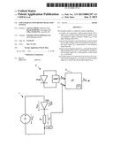
[0015] FIG. 1 represents the basic diagram of the detection system of the invention,
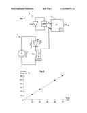
[0016] FIG. 2 represents the curve of the increase in the current passing through the light-emitting diode (in %) as a function of measured temperature (Temp) (in ° C.).
DETAILED DESCRIPTION OF AT LEAST ONE EMBODIMENT
[0017] The invention relates to a detection system intended in particular for determining the concentration of a gas, such as for example carbon dioxide. The detection system of the invention exhibits the advantage of consuming very little energy during each measurement and of not degrading the signal-noise ratio.
[0018] With reference to FIG. 1, the detection system of the invention comprises an emitter 1 comprising a light-emitting diode (DEL) able to emit a luminous signal and a power supply source A to which the light-emitting diode DEL is connected. The power supply source A consists of a voltage source delivering a constant voltage Valim so as to be able to apply a constant voltage VDEL to the light-emitting diode DEL. With a constant voltage VDEL across the terminals of the light-emitting diode DEL, the current IDEL which passes through the diode evolves substantially with temperature since the forward bias voltage of the light-emitting diode DEL varies inversely with temperature. Consequently, at constant voltage, the current which passes through the light-emitting diode DEL increases in a quasi-linear manner as the temperature increases. The curve represented in FIG. 2 makes it possible to illustrate this phenomenon.
[0019] The detection system of the invention also comprises a receiver 2 which is distant with respect to the emitter 1 and comprising for example a photodiode (PHD) intended to sense the luminous signals emitted by the emitter 1 and a current amplifier AMP making it possible to transform the electrical current generated by virtue of the photodiode PHD into a first input signal Sin1 utilizable downstream by processing means 3. The gas to be detected is typically placed between the emitter 1 and the receiver 2.
[0020] As the light-emitting diode DEL is powered by a constant voltage source, the detection system also comprises means for measuring the current IDEL passing through the light-emitting diode DEL. The variation in the measured current IDEL is representative of the variation in the temperature influencing the optical power of the light-emitting diode DEL. The measurement means comprise for example a measurement resistor Rm connected in series with the light-emitting diode DEL, whose voltage VR is monitored by the processing means 3 with a view to deducing therefrom the current IDEL passing through the light-emitting diode DEL. In FIG. 1, the current IDEL is represented by a second input signal Sin2 applied to the processing means 3.
[0021] The first input signal Sin1 and the second input signal Sin2 are for example transformed into digital signals by analogue-digital converters implemented in the processing means 3. The processing means 3 comprise a microcontroller μC intended to process the two digital signals obtained so as to determine an output signal Sout representative of the state of detection. The processing consists in determining an output voltage, corresponding to the concentration of the gas to be measured, on the basis of the first input signal Sin1, of the second input signal Sin2 and of temperature calibration parameters (T°) initially stored in the microcontroller μC. These calibration parameters T° are for example stored in a memory of the microcontroller μC and are applied to the second input signal Sin2 so as to take account of the influence of the temperature in the determination of the output signal Sout.
[0022] Moreover, since the light-emitting diode DEL is powered voltage-wise, as the temperature increases, the optical power of the diode DEL at constant current decreases and therefore the signal-noise ratio SNR decreases. Now, when the diode DEL is powered by a constant voltage, its current increases as the temperature increases. Consequently, the loss of optical power is limited, as is the degradation in the signal-noise ratio SNR.
User Contributions:
Comment about this patent or add new information about this topic:
| People who visited this patent also read: | |
| Patent application number | Title |
|---|---|
| 20220206727 | NON-TRANSITORY COMPUTER-READABLE RECORDING MEDIUM, AND PRINTING SYSTEM |
| 20220206726 | OUTPUT SYSTEM, SYSTEM, AND OUTPUT METHOD |
| 20220206725 | PROGRAMMABLE REDACTION FOR SECURE UI, REPORTS, SCANS, AND PRINTS |
| 20220206724 | Printer |
| 20220206723 | PRINT DATA GENERATING DEVICE AND PRINTING DEVICE GENERATING PRINT DATA FOR CREATING PRINTED MEDIUM |
Images included with this patent application:
 |  |
| Similar patent applications: | |
| Date | Title |
|---|---|
| 2009-01-22 | Collision detector |
| 2009-01-22 | Interconnect joint |
| 2009-01-22 | Mask registration correction |
| New patent applications in this class: | |
| Date | Title |
|---|---|
| 2016-12-29 | Broadband photoresistor |
| 2016-12-29 | Integrated device for temporal binning of received photons |
| 2016-07-14 | Optical lens with ambient light sensing |
| 2016-07-07 | Portable device for quantifying thermochromatic coating signatures |
| 2016-06-30 | Optical filter device, optical module, and electronic equipment |
| New patent applications from these inventors: | |
| Date | Title |
|---|---|
| 2015-12-31 | Optical chamber for a gas detection device |
| 2015-09-10 | Power supply device and method for wireless sensor unit |
| 2014-04-17 | Detection device provided with a transimpedance circuit |
| Top Inventors for class "Radiant energy" | |
| Rank | Inventor's name |
|---|---|
| 1 | Jason Lee Wildgoose |
| 2 | Osamu Wakabayashi |
| 3 | Toshio Kameshima |
| 4 | Tomoyuki Yagi |
| 5 | Katsuro Takenaka |