Patent application title: Milling Assembly
Inventors:
David Joe Steele (Arlington, TX, US)
David Joe Steele (Arlington, TX, US)
Assignees:
HALLIBURTON ENERGY SERVICES, INC.
IPC8 Class: AE21B2900FI
USPC Class:
166298
Class name: Processes perforating, weakening, bending or separating pipe at an unprepared point perforating, weakening or separating by mechanical means or abrasive fluid
Publication date: 2013-01-03
Patent application number: 20130000907
Abstract:
A milling assembly and methods for milling an opening for a lateral
wellbore in a section of casing or in a cement liner.Claims:
1. A milling assembly, comprising: a tubular body with an opening at an
upper end and another opening at a lower end, the lower end having an
inside diameter and an outside diameter; and a cutting surface on the
lower end extending from the inside diameter up to, but not including,
the outside diameter.
2. The milling assembly of claim 1, further comprising a retractable retaining element positioned within the tubular body between another opening at the lower end and the opening at the upper end.
3. The milling assembly of claim 2, further comprising a filter positioned within the tubular body between the retaining element and the opening at the upper end.
4. The milling assembly of claim 3, further comprising another retractable retaining element positioned within the tubular body between the retaining element and the filter.
5. The milling assembly of claim 1, further comprising: a side opening in the tubular body between the opening at the upper end and the another opening at the lower end; and another side opening in the tubular body between the side opening and another opening at the lower end or the opening at the upper end.
6. The milling assembly of claim 4, wherein the retaining element and the other retaining element are closed and extend into an annulus of the tubular body when there is no circulation of fluid through the annulus.
7. The milling assembly of claim 6, wherein the retaining element and the other retaining element are open and substantially parallel to an axis of the tubular body when there is circulation of fluid through the annulus.
8. The milling assembly of claim 1, further comprising another cutting surface on the inside diameter of the lower end.
9. The milling assembly of claim 1, further comprising a whipstock positioned to engage the cutting surface and redirect the cutting surface toward an adjacent section of casing.
10. The milling assembly of claim 9, wherein the whipstock is substantially solid.
11. A milling assembly, comprising: a tubular body with an opening at an upper end and another opening at a lower end, the lower end having an inside diameter and an outside diameter; a cutting surface on the lower end; and a whipstock positioned to engage the cutting surface and redirect the cutting surface toward an adjacent section of casing.
12. The milling assembly of claim 11, further comprising a retractable retaining element positioned within the tubular body between the other opening at the lower end and the opening at the upper end.
13. The milling assembly of claim 12, further comprising a filter positioned within the tubular body between the retaining element and the opening at the upper end.
14. The milling assembly of claim 13, further comprising another retractable retaining element positioned within the tubular body between the retaining element and the filter.
15. The milling assembly of claim 11, further comprising: a side opening in the tubular body between the opening at the upper end and the another opening at the lower end; and another side opening in the tubular body between the side opening and the other opening at the lower end or the opening at the upper end.
16. The milling assembly of claim 14, wherein the retaining element and the other retaining element are closed and extend into an annulus of the tubular body when there is no circulation of fluid through the annulus.
17. The milling assembly of claim 16, wherein the retaining element and the other retaining element are open and substantially parallel to an axis of the tubular body when there is circulation of fluid through the annulus.
18. The milling assembly of claim 11, wherein the cutting surface extends from the inside diameter up to, but not including, the outside diameter.
19. The milling assembly of claim 18, further comprising another cutting surface on the inside diameter of the lower end.
20. The milling assembly of claim 11, wherein the whipstock is substantially solid.
21. A method for milling an opening for a lateral wellbore in a section of casing or in a cement liner, comprising: lowering a milling assembly on a drilling string toward a whipstock in a wellbore partially lined with the section of casing and the cement liner; milling the opening in the section of casing or in the cement liner when the milling assembly engages the whipstock; circulating a fluid through the milling assembly during the milling of the opening in the section of casing or in the cement liner; and retaining cuttings within the milling assembly when the fluid stops circulating through the milling assembly.
22. The method of claim 21, further comprising retrieving the cuttings within the milling assembly when the milling assembly is removed from the wellbore.
23. The method of claim 21, further comprising filtering the cuttings within the milling assembly during circulation of the fluid through the milling assembly.
24. The method of claim 21, wherein the cuttings are retained within the milling assembly by a retaining element.
25. The method of claim 24, wherein the retaining element is in an open position when the fluid is circulating through the milling assembly.
26. The method of claim 24, wherein the retaining element is in a closed position when the fluid stops circulating through the milling assembly.
27. The method of claim 21, further comprising pre-milling a portion of the section of casing to form an opening representing a pre-milled window.
28. The method of claim 21, wherein the fluid circulating through the milling assembly enters an opening at one end of the milling assembly and exits through a side opening in the milling assembly into an annulus between the milling assembly and the section of casing or another section of casing.
29. The method of claim 28, wherein the fluid circulating through the milling assembly enters another opening at another end of the milling assembly and exits through another side opening in the milling assembly into the annulus between the milling assembly and the section of casing or the another section of casing.
30. The method of claim 27, further comprising positioning the whipstock within the section of casing below the pre-milled window.
Description:
CROSS-REFERENCE TO RELATED APPLICATIONS
[0001] Not applicable.
STATEMENT REGARDING FEDERALLY SPONSORED RESEARCH
[0002] Not applicable.
FIELD OF THE INVENTION
[0003] The present invention generally relates to a milling assembly and methods for milling an opening for a lateral wellbore in a section of casing or in a cement liner using the milling assembly.
BACKGROUND OF THE INVENTION
[0004] Wellbores are typically drilled using a drilling string with a drill bit secured to the lower free end and then completed by positioning a casing string within the wellbore and cementing the casing string in position. The casing increases the integrity of the wellbore and provides a flow path between the surface and a selected subterranean formation for the injection of treating chemicals into the surrounding formation to stimulate production, for receiving the flow of hydrocarbons from the formation, and for permitting the introduction of fluids for reservoir management or disposal purposes.
[0005] During conventional milling and/or drilling operations for completion of a lateral wellbore, drilling fluid is typically pumped downhole through a conventional milling assembly on the drilling string until it exits the bottom of the drilling string and circulates back up through the annulus between the drilling string and the casing as illustrated in FIG. 1. In FIG. 1, a cross-sectional elevation view of a conventional wellbore 100 illustrates the typical path of drilling fluid during milling and/or drilling operations. The drilling fluid passes through the drilling string 102, exits an opening 104 at the bottom of the drilling string 102 and circulates back up through the annulus 106 between the drilling string 102 and the intermediate casing 108. During the milling and/or drilling operations, cuttings 110 may be captured within the drilling fluid and deposited at various positions within the wellbore 100 as illustrated in FIG. 1. For example, cuttings 110, may be deposited where the intermediate casing 108 joins the surface casing 112, at the wellhead 114 and/or in a blowout preventer 116. The cuttings 110 may include casing remnants, cement and/or formation debris from the milling and/or drilling operations. Due to a low annular velocity in the annulus 106 above the intermediate casing 108, the cuttings 110 may accumulate more around the wellhead 114 and the blowout preventer 116. As a result, cuttings 110 may become severely compacted causing failure of the wellhead 114 and/or blowout preventer 116. This problem is compounded when the drilling fluid stops pumping through the drilling string 102 after the milling and/or drilling operations.
[0006] Although there are conventional tools that reverse circulate the drilling fluid in a manner that captures cuttings within the tool, these tools are typically designed for retrieving other stuck tools in the drilling string. These conventional "fishing" tools are often designed to avoid cutting the casing while other tools that become stuck within the wellbore are cut free with the use of a fishing tool. As a result, this type of conventional fishing tool cannot be used to mill an opening for a lateral wellbore in a section of the casing.
SUMMARY OF THE INVENTION
[0007] The present invention overcomes one or more of the prior art disadvantages by using an improved milling assembly to retain cuttings within the milling assembly during completion of a lateral wellbore.
[0008] In one embodiment the present invention includes a milling assembly, comprising: i) a tubular body with an opening at an upper end and another opening at a lower end, the lower end having an inside diameter and an outside diameter; and ii) a cutting surface on the lower end extending from the inside diameter up to, but not including, the outside diameter.
[0009] In another embodiment, the present invention includes a milling assembly, comprising: i) a tubular body with an opening at an upper end and another opening at a lower end, the lower end having an inside diameter and an outside diameter; ii) a cutting surface on the lower end; and iii) a whipstock positioned to engage the cutting surface and redirect the cutting surface toward an adjacent section of casing.
[0010] In yet another embodiment, the present invention includes a method for milling an opening for a lateral wellbore in a section of casing or in a cement liner, comprising: i) lowering a milling assembly on a drilling string toward a whipstock in a wellbore partially lined with the section of casing and the cement liner; ii) milling the opening in the section of casing or in the cement liner when the milling assembly engages the whipstock; iii) circulating a fluid through the milling assembly during the milling of the opening in the section of casing or in the cement liner; and iv) retaining cuttings within the milling assembly when the fluid stops circulating through the milling assembly.
[0011] These and other objects, features and advantages of the present invention will become apparent to those skilled in the art from the following description of the various embodiments and related drawings.
BRIEF DESCRIPTION OF THE DRAWINGS
[0012] The invention will be described with reference to the accompanying drawings, in which like elements are referenced with like reference numbers, and in which:
[0013] FIG. 1 is a cross-sectional elevation view of a conventional wellbore illustrating the typical path of drilling fluid during milling and/or drilling operations.
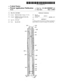
[0014] FIG. 2 is a cross-sectional elevation view illustrating one embodiment of the milling assembly according to the present invention.
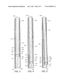
[0015] FIG. 3 is a cross-sectional elevation view of the milling assembly illustrated in FIG. 2 as it engages a whip stock within a section of casing.
[0016] FIG. 4 is a cross-sectional elevation view of the milling assembly illustrated in FIG. 3 as it traverses the whip stock within the section of casing.
[0017] FIG. 5 is a cross-sectional elevation view of the milling assembly illustrated in FIG. 4 as it traverses the whip stock and exits a pre-milled window in the section of casing.
DETAILED DESCRIPTION OF THE PREFERRED EMBODIMENTS
[0018] In the following detailed description of the preferred embodiments, references to the accompanying drawings that form a part hereof, and in which is shown by way of illustration specific preferred embodiments in which the invention may be practiced. These embodiments are described in sufficient detail to enable those skilled in the art to practice the invention, and it is to be understood that other embodiments that may be utilized and that logical changes may be made without departing from the spirit and scope of the present invention. The claimed subject matter thus, might also be embodied in other ways, to include structures, steps and combinations similar to the ones described herein, in conjunction with other present or future technologies. The following detailed description is therefore, not to be taken in a limiting sense, and the scope of the present invention is defined only by the appended claims.
[0019] Referring now to FIG. 2, a cross-sectional elevation view illustrates one embodiment of an improved milling assembly 200 according to the present invention. The milling assembly 200 includes a tubular body 202 with an annulus 203 and an axis 207. The body 202 further includes an opening 204 at an upper end and another opening 206 at a lower end. The lower end of the body 202 has an inside diameter 208 and an outside diameter 210. A cutting surface 212 on the lower end of the body 202 extends from the inside diameter 208 up to the outside diameter 210. Another cutting surface 224 may be included on the inside diameter 208 of the lower end of the body 202. And, another cutting surface 225 may be included above the lower end of the body 202 on the outside diameter 210.
[0020] The milling assembly 200 includes a retractable retaining element 214 positioned within the body 202 between another opening 206 at the lower end of the body 202 and the opening 204 at the upper end of the body 202. A filter 216 may be positioned within the body 202 between the retaining element 214 and the opening 204 at the upper end of the body 202. Another retractable retaining element 218 may be positioned within the body 202 between the retaining element 214 and the filter 216. As illustrated in FIGS. 2-5, the retaining element 214 and the another retaining element 218 are closed and extend into the annulus 203 of the body 202 when there is no circulation of fluid through the annulus 203. However, the retaining element 214 and the another retaining element 218 may be open and substantially parallel to the axis 207 of the body 202 when there is circulation of fluid through the annulus 203. The retaining element 214 and the another retaining element 218 may be closed and extend into the annulus 203 of the body 202 when there is no circulation of fluid through the annulus 203 by means of a spring-loaded mechanism or other well known means to force the retaining element 214 and the another retaining element 218 into a closed position. As such, the means or mechanism used to place the retaining element 214 and the another retaining element 218 in the closed position may be retractable so that when there is circulation of fluid through the annulus 203 of the body 202, the retaining element 214 and the another retaining element 218 are open and substantially parallel to the axis of the body 202. Alternatively, each retaining element and/or additional retaining elements may be designed to permit circulation of fluid through the annulus 203 of the body 202 and retain various types of debris. The retaining element 214 may be used to retain portions or remnants of the sleeve 228 after the milling assembly 200 has milled an opening there through and there is no longer any circulation of the fluid through the annulus 203 of the body 202. Likewise, the another retaining element 218 may be used to retain additional debris in the form of cuttings from the casing, the cement liner and/or the formation after the milling assembly 200 has completed milling and/or drilling and there is no longer circulation of fluid through the annulus 203 of the body 202. The filter 216 may be used to trap cuttings during operation of the milling assembly 200 when there is circulation of fluid through the annulus 203 of the body 202.
[0021] A side opening 220 is located between the opening 204 at the upper end of the body 202 and the another opening 206 at the lower end of the body 202. Another side opening 222 is located between the side opening 220 and the opening 204 at the upper end of the body 202.
[0022] The body 202 may be positioned within a section of casing 226 that includes a pre-milled window 230 through the casing 226. A sleeve 228, preferably made of aluminum, may be connected to the casing 226 around the pre-milled window 230 to protect the milling assembly 200 from debris and cement as the casing 226 is secured within a wellbore. Alternatively, the sleeve 228 may be made of a fiberglass mesh.
[0023] The milling assembly described herein may be used to mill an opening for a lateral wellbore in the manner described in reference to FIGS. 3-5. The opening for the lateral wellbore may be formed by milling and/or drilling through a section of casing, the cement liner and/or the formation.
[0024] Referring now to FIG. 3, a cross-sectional elevation view of the milling assembly 200 is illustrated as it engages a whip stock 302 within the section of casing 226. The milling assembly 200 may be lowered on a drilling string toward the whip stock 302 in a wellbore partially lined with the section of casing 226 and a cement liner. As the milling assembly 200 is lowered, it may be rotated before or during engagement with the whip stock 302. The whip stock 302 may be positioned within the section of casing 226 at a predetermined depth in the wellbore, which may include below the pre-milled window 230. The pre-milled window 230 may be formed at the surface of the wellbore, before the casing is installed, by pre-milling a portion of the section of casing 226 to form an opening representing the pre-milled window 230.
[0025] Referring now to FIGS. 4-5, the milling assembly 200 is rotated as it engages the whip stock 302 and begins to mill an opening in the section of casing 226 through sleeve 228 and/or the cement liner. If the section of casing 226 includes the pre-milled window 230 and the sleeve 228 is not necessary, then the opening may be milled in just the cement liner. In most situations, however, the opening is milled in the section of casing 226 and in the cement liner when the milling assembly 200 engages the whip stock 302. During milling and/or drilling operations, a fluid (e.g., drilling fluid) may be circulated through the milling assembly 200. The fluid may carry cuttings and other debris through the milling assembly 200. The fluid, for example, may enter the opening 204 at the upper end of the body 202 and exit through the side opening 220 in the body 202 into an annulus between the milling assembly 200 and the section of casing 226 or another section of casing. The fluid circulating through the milling assembly 200 may enter another opening 206 at the lower end of the body 202 and exit through another side opening 222 in the body 202 into the annulus between the milling assembly 200 and the section of casing 226 or another section of casing. In this manner, the fluid circulating through the milling assembly 200 is often referred to as reverse circulation.
[0026] During circulation of the fluid through the milling assembly 200, cuttings and other debris may be filtered within the milling assembly 200 by the filter 216. Further, the cuttings and other debris may be retained within the milling assembly 200 when the fluid stops circulating through the milling assembly 200. The cuttings and other debris may be retained by the retaining element 214 and the another retaining element 218 when both are in a closed position after the fluid stops circulating through the milling assembly 200. The cuttings and other debris may be retrieved from within the milling assembly 200 when the milling assembly 200 is removed from the wellbore.
[0027] Although specific embodiments have been illustrated and described herein, it will be appreciated by those of ordinary skill in the art that any arrangement which is calculated to achieve the same purpose may be substituted in the specific embodiments shown. This application is intended to cover any adaptations or variations of the present invention. Therefore, it is manifestly intended that this invention be limited only by the following claims and equivalents thereof.
User Contributions:
Comment about this patent or add new information about this topic:
Images included with this patent application:
 |  |
 |
| Similar patent applications: | |
| Date | Title |
|---|---|
| 2013-10-24 | Milling assembly |
| 2010-12-02 | Sealing assembly |
| 2010-12-09 | Sealing assembly |
| 2011-05-26 | Load bearing assembly |
| 2014-01-02 | Pumping assembly |
| New patent applications in this class: | |
| Date | Title |
|---|---|
| 2019-05-16 | Flapper bypass tool |
| 2019-05-16 | Apparatus and method for cutting casings |
| 2016-06-09 | Internal tractor system for downhole tubular body |
| 2016-06-02 | A gas lift system and a gas lift method |
| 2016-06-02 | Jet perforating device for creating a wide diameter perforation |
| New patent applications from these inventors: | |
| Date | Title |
|---|---|
| 2021-01-14 | Actuator for multilateral wellbore system |
| 2021-01-14 | Actuator for multilateral wellbore system |
| 2018-12-27 | Non-rotating drill-in packer |
| 2016-05-12 | Mainbore clean out tool |
| 2016-04-21 | Casing window assembly |
| Top Inventors for class "Wells" | |
| Rank | Inventor's name |
|---|---|
| 1 | Michael L. Fripp |
| 2 | Jean Marc Lopez |
| 3 | Michael H. Johnson |
| 4 | Jørgen Hallundbaek |
| 5 | Dennis P. Nguyen |