Patent application title: Plow Blade Wing
Inventors:
Charles O. Knott (Godfrey, CA)
Brian Kirk (Bath, CA)
IPC8 Class: AE02F3815FI
USPC Class:
37233
Class name: Snow or ice removing or grooming by portable device vehicle mount with obstacle responsive trip, or yieldable tool (e.g., brush) resilient impeller or blade
Publication date: 2012-12-13
Patent application number: 20120311893
Abstract:
A wing extension for a plow blade is disclosed which comprises an
extension plow blade having a plow surface for plowing a desired
material; and mounting means for pivotally mounting the extension plow
blade to an existing plow blade. The extension plow blade is pivotable
from a first use position in alignment with the existing plow blade to a
second rearwardly deflected position on contact with an immovable object.
A biasing member, such as a torsion spring, is provided for biasing the
extension plow blade in the first use position.Claims:
1. A wing extension for a plow blade, comprising: an extension plow blade
having a plow surface for plowing a desired material; mounting means for
pivotally mounting the extension plow blade to an existing plow blade,
said extension plow blade pivotable from a first use position in
alignment with the existing plow blade to a second rearwardly deflected
position; and biasing means for biasing the extension plow blade in the
first use position.
2. The wing extension according to claim 1, wherein the biasing means is at least one torsion spring.
3. The wing extension according to claim 1, wherein the biasing means is in the form of at least two torsion springs.
4. The wing extension according to claim 1, wherein said mounting means comprises: a frame member having a first edge for fixedly mounting said mounting means to the existing plow blade and a second edge including hinge means for pivotally mounting said wing extension.
5. The wing extension according to claim 2, further comprising adjustment means for adjusting a load on the torsion springs.
6. The wing extension according to claim 4, wherein the wing extension includes further hinge means, the further hinge means being complementary to the hinge means of the mounting means, said hinge means and further hinge means being barrel hinges forming a hollow passage therethrough when aligned.
7. The wing extension according to claim 5, wherein the adjustment means comprises a rod extending through the hollow passage of the hinge means, said spring mounted on said rod between hinge means.
8. The wing extension according to claim 1, wherein said wing member is movable to a third position, said third position being a storage position where the wing extension member is rotated rearward to a position parallel to a rear surface of the existing plow blade.
9. The wing extension according to claim 8, wherein the wing member is movable to said third position through hydraulic means or mechanical means actuated by an operator.
10. The wing extension according to claim 8, further comprising locking means for locking the wing extension in said third position.
11. A wing extension for use with a plow blade, said wing extension comprising: a frame member; a plow surface for contact with a substance to be plowed, said plow surface fixedly mounted to said frame member; a mounting member for pivotably mounting said frame member to the plow blade, such that said frame member is pivotable from a first use position in alignment with the plow blade, and a second deflected position at a rearward angle with respect to the plow blade; biasing means for biasing said frame member in a first use position.
12. The wing extension according to claim 11 wherein the frame member is also pivotable to a third position, wherein the third position is a non-use storage position, parallel to a back surface of the plow blade.
13. The wing extension according to claim 12, further including releasable lock means for locking the frame member in the third position.
14. The wing extension according to claim 11, wherein said biasing means is in the form of at least one torsion spring.
15. The wing extension member according to claim 14, further including torque adjustment means for adjusting the torque on said at least one torsion spring.
16. The wing extension according to claim 1, wherein the plow blade is a snow plow blade.
17. A snow plow blade comprising: a main snow plow blade having a pair of ends; at least one wing extension pivotably mounted with respect to at least one of the ends and pivotable from a first use position to a second rearwardly deflected position; biasing means for biasing the at least one wing extension in the first use position; wherein when in said first use position, the wing extension is in alignment with the main snow plow blade.
18. The snow plow blade according to claim 17, further comprising a mounting frame having first and second mounting surfaces, said first mounting surface adapted to secure the mounting frame to the main snow plow blade and the second mounting surface adapted for pivotal mounting of said at least one wing extension.
19. The snow plow blade according to claim 17, wherein said biasing means is in the form of at least one torsion spring.
20. The snow plow blade according to claim 19, further comprising adjusting means for adjusting torque on the at least one torsion spring.
21. The snow plow blade according to claim 17, wherein the wing extension is pivotable to a third position, said third position being a storage position where the wing extension is folded against a rear surface of the main snow plow blade.
22. The snow plow blade according to claim 21, further comprising lock means to releasably lock the wing extension in said third position.
23. The snow plow blade according to claim 21, further comprising actuating means for moving said wing extension from said first use position to said third storage position.
24. The snow plow blade according to claim 21, wherein said actuating means is selected from the group consisting of mechanical, pneumatic and electric means.
Description:
FIELD OF THE INVENTION
[0001] The present invention relates to a wing for a plow blade. More specifically, the present invention relates to a wing for a plow blade where the wing is rotatable from a use position to a folded back or non-use position on impact with a solid object and then returns to its use position once the object has been passed.
BACKGROUND OF THE INVENTION
[0002] It is often desired to extend the working width of a plow blade through the use of wings or extension members. Such wing extensions have been used on all manner of plow blades including those used in farm equipment, construction equipment, snow removal equipment, etc.
[0003] In the area of snow removal, vehicles are routinely converted to a snow plow through the provision of a snow plow blade which can be affixed to the front end of a vehicle.
[0004] Also known is the provision of wings or extensions which can be affixed to a snow plow blade to extend the working width of the blade. In some cases the wings or extensions are affixed to an existing blade in such a manner to permit movement of the wings or extensions in response to movement of the blade to which they are attached. Further such wings or extensions can be rotatably mounted with respect to the central blade to permit the wings to be folded back when not in use for easier transport/storage.
[0005] U.S. Patent Publication 2009/0307941 to Gamble, II discloses a central plow blade including end wings which are movable independently of the main or central plow blade. The publication provides for wing blades coupled to each end of the center blade where the wing blades are pivotally connected to the center blade. Each wing blade is configured to independently pivot from a first position to a second position more than 90 degrees relative to the central blade. The plow includes an actuator to facilitate movement of each wing blade by an operator of the plow.
[0006] U.S. Pat. No. 6,751,894 to Verseef relates to a snow plow with a central plow blade and wing blades rotatably attached thereto. The wing blades can be folded inwardly and outwardly with respect to the main blade. The rotation of the wing blades with respect to the main blade permits the snow removal device to be partially collapsed making transportation and or storage of the snow plow blade less difficult.
[0007] When a snow plow blade encounters a trip hazard or other solid immovable object, significant stresses are transferred from the blade which can cause damage to the blade or vehicle. Additionally, when a trip hazard or solid object is encountered, it can cause the vehicle to jump and this sudden unexpected jolt can distract the driver, possibly causing an accident due to loss of vehicle control.
[0008] In this regard it is known to provide a trip plate or trip edges to a snow plow. Such a trip plate mechanism is provided at the lower edge of the blade which is in contact with the pavement or other surface to be plowed. U.S. Pat. No. 5,697,172 to Verseef discloses such a trip edge. Such a trip edge enables the plow to pass over trip hazards without transferring significant impact forces to the plow. The trip edge is mounted to the lower edge of the plow blade in a displaceable manner so that the trip edge swings up and away from the pavement when a trip hazard is encountered. Such a system works for trip hazards such as manhole covers, raised portions etc.
[0009] As noted hereinabove, it is often desirable to extend the width of a plow blade with wing or extension members so that a wider area can be plowed in one sweep. However, the provision of wings or blade extensions can cause problems when solid or immovable objects are encountered by the wing blades. As plows are typically moving at speeds in excess of 10 mph, considerable damage can result to both the vehicle, existing plow blade and wing blades, when the wing blades encounter an immovable or solid object, such as a large rock, curb, etc. Additionally, there is the added hazard of the driver being distracted and potentially losing control of the vehicle due to the jolt occurring on impact with an object. Still further, in the case of snow removal operations when a heavy load of snow is on the wing blade, the plow vehicle will tend to want to slide sideways, this is especially true in icy conditions. This side slip can also be hazardous.
SUMMARY OF THE INVENTION
[0010] The present invention provides wings or extension members for a plow blade to extend the working width of the blade and reduce the stresses to the wings, plow blade and vehicle when the wings impact on a solid or immovable object. Further the wing extension member of the present invention reduces side slip of a snow plow vehicle which is hazardous and which can occur when an excessive snow load is on the wing blade and icy conditions are encountered.
[0011] In accordance with one embodiment of the present invention there is provided a wing extension for a plow blade which comprises an extension plow blade having a plow surface for plowing a desired material; and mounting means for pivotally mounting the extension plow blade to an existing plow blade such that the extension plow blade is pivotable from a first use position in alignment with the existing plow blade to a second rearwardly deflected position. A biasing means is provided for biasing the extension plow blade in the first use position.
[0012] In accordance with another embodiment of the present invention, there is provided a wing extension for use with a plow blade. The wing extension comprises: a frame member; a plow surface for contact with a substance to be plowed where the plow surface is fixedly mounted to said frame member. A mounting member is provided for pivotably mounting the frame member to the plow blade, such that the frame member is pivotable from a first use position in alignment with the plow blade, and a second deflected position at a rearward angle with respect to the plow blade. Biasing means are provided for biasing the frame member in a first use position.
[0013] Yet another embodiment of the present invention provides a snow plow blade comprising: a main snow plow blade having a pair of ends; at least one wing extension pivotably mounted with respect to at least one of the ends and pivotable from a first use position to a second rearwardly deflected position; and biasing means for biasing the at least one wing extension in the first use position. When in the first use position, the wing extension is in alignment with the main snow plow blade.
BRIEF DESCRIPTION OF THE DRAWINGS
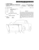
[0014] FIG. 1A is a perspective view of one embodiment of the present invention showing the wings or extensions of the present invention mounted on both sides of a plow blade and in their normal use position;
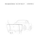
[0015] FIG. 1B is a perspective view of an embodiment of the present invention, showing the wings in their deflected position;
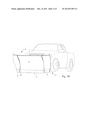
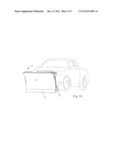
[0016] FIG. 1C is a perspective view of an embodiment showing the wing blade in a storage or non-use position;
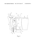
[0017] FIG. 2 is a front expanded view of the components of the wing blade of the present invention;
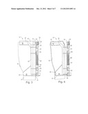
[0018] FIG. 3 is a rear view of the wing blade and mounting mechanism of the present invention when the wing is in a normal use position;
[0019] FIG. 4 is a rear view of the wing blade and mounting mechanism of the present invention when the wing is in a deflected position, such as on encountering an immovable object;
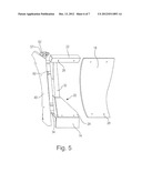
[0020] FIG. 5 is a front view of the wing, showing the frame in an assembled condition, and the backing sheet removed; and
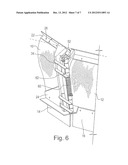
[0021] FIG. 6 is a partial rear view of another embodiment of the wing for use as a snow scoop and mounted on an existing snow plow blade at an angled orientation.
DETAILED DESCRIPTION
[0022] Referring initially to FIGS. 1A-1C, these figures illustrate the wing or extension members 10 of the present invention pivotably mounted to an existing snow plow blade 12 on a truck. Although the figures illustrate the wing extension mounted to a snow plow blade, it will be appreciated that the wing extensions of the present invention could also be utilized with other plow blades, such as those used in the fanning and construction industries.
[0023] Although the figures illustrate two wing members 10, one mounted on each end of the existing snow plow blade 12, only a single wing mounted on one end of the snow plow blade 12 can be used if desired.
[0024] The wing members 10 include a lower cutting edge 14, generally in alignment with the lower cutting edge 16 of the existing blade 12.
[0025] In FIG. 1A the wing blades 10 are shown in alignment with the existing blade 12; this is the normal use position when plowing.
[0026] In FIG. 1B, the wing blades 10 are shown in their deflected position which would occur on impact with a solid immovable object, such as a curb or rock, during the plowing operation. The wing extension would also be deflected into a rearward position in situations where the load of material being plowed impacting on the blade is excessively heavy to thus reduce stresses on the plow and, in the case of snow removal operations, to avoid side slip of the vehicle.
[0027] In FIG. 1C, the wing blades 10 are shown in a storage or non-use position, where the wing blades 10 are folded rearwardly back into a position where they can be secured to a rear face of the snow plow blade 12. Such a storage position is used when an operator does not wish to use the wing blades 10, such as during transportation between locations or when plowing narrower areas. The wing blades 10 can be moved into a storage position manually and locked into place. In other embodiments, the wing blades can be moved into a storage position through the use of actuators which can be in the form of electrical or hydraulic actuators or any other suitable actuators, which could be activated by an operator of the vehicle.
[0028] As will be discussed hereinafter in more detail, the wing blades 10 are pivotably mounted with respect to existing plow blade 12. A biasing member, such as a torsion spring or springs 60, is provided such that the wing blades 10 are biased in an aligned or use position with respect to the existing plow blade 10 so that once the immovable object has been passed (deflecting the wing blade 10) the wing blades 10 will automatically return to their normal use position in alignment with the existing plow blade 12.
[0029] When the plow blade 12 is mounted to a vehicle for snow removal purposes, it is typically mounted in a forwardly angled position, thus the torsion spring 60 is preferably at an angled axis with respect to the surface to be plowed. Due to the angled axis, the snow being plowed will be directed off the wing blade 10 in an upward direction when the wing blade 10 is deflected rearward, this trajectory will deposit the snow on top of an existing snow bank thus reducing fall back of snow onto the road.
[0030] FIG. 2 illustrates the components of the wing blade 10 in an expanded view. FIGS. 3 and 4 are rear views showing the wing in assembled conditions, with FIG. 3 depicting the rear view when the wing is in its normal use position generally within the same plane as the existing plow blade 12 and FIG. 4 when the wing is in a deflected position which would result on encountering an immovable object or in the case of a heavy load on the wing blade 10. FIG. 5 is a front view of the wing blade 10 and mounting 40 showing the sheet or panel 18 removed from the frame 20.
[0031] The wing blade 10 includes the panel member 18. The panel can be made of any material suitable to withstand the forces of the substance being plowed, such as snow during a snow removal operation. In a preferred arrangement, the sheet is a 3/8'' polystyrene sheet, although other materials could be utilized. The panel member 18 is mounted to a frame member 20. The frame member 20 includes top and bottom support members 22, 24 including mounting apertures 26 for mounting of the panel 18 thereon. Panel 18 includes mounting apertures 28 which correspond to the apertures 26 of the support members 22, 24, which permit the bolting of the panel 18 to the support members 22, 24.
[0032] The frame member 20 is provided with a rear support column 32 connecting the top and bottom support members 22, 24. Further attached to the support column 32 are hinge arms 34 including hinge members 36 extending therefrom. The hinge members are in the form of barrel hinge members having hollow cylindrical sections, although other hinge arrangements can be utilized.
[0033] A mounting member 40 is provided for mounting of frame member 20 to an existing snow plow blade (not shown). The mounting member 40 includes hinge members 42 which are complementary to the hinge members 36 of the frame member 20. One end of the mounting member 40 is fixedly secured to an existing snow plow blade 12 through the use of bolts or other fixing means (not shown) and the other end of the mounting member 40 includes the hinge members 42 for mounting the frame member 20 thereto.
[0034] The hinge members 36 of the frame member 20 and the hinge members 42 of the mounting member 40 are aligned together, with the hinge members 36 being in a position adjacent the complementary hinge members 42. A steel bar or rod 50 slides through the hollow central shaft created by the hinge members 36, 42 when aligned to retain the hinge members together thus affixing the mounting member 40 and the frame member 20 to one another and allow for pivoting or rotation of the frame member 20 with respect to the mounting member 40.
[0035] The wing blade 10 can be readily removed from the mounting member 40 through removal of the steel rod 50 and disengagement of the hinge members 36,42. In this manner, the wing blade 10 can be easily removed when desired with the mounting member 40 being retained on the existing plow blade 12. This arrangement permits the removal and reattachment of the wing member in a quick and easy manner.
[0036] Also provided is a biasing member, such as at least one torsion spring 60 which can be centrally located on the bar 50 in a position between upper and lower hinge members. The torsion spring 60 includes an anchor pin 62 which is received and retained in an aperture 39 on the hinge arm 34. The spring further includes a lower portion 61 which includes means 63 for releasably securing the spring 60 to the bar 50. In the illustrated embodiment, the means 63 for releasably securing the spring 60 to the bar 50 is in the form of a threaded aperture and bolt (not shown) arrangement. Tightening of the bolt through the aperture frictionally secures the lower end 61 of the spring 60 to the bar 50.
[0037] In a preferred embodiment, the upper end of the torsion spring 60 is retained in position by portion 101 of hinge 36 which fits inside the top portion of spring 60 and by the anchor pin 62. The means 63 for releasably securing the spring 60 to the bar 50 retains the lower end of the spring 60 in position. With the spring 60 securely in place, torsion can be applied thereto and retained as will be discussed hereinafter.
[0038] The bar 50 also includes an adjustment mechanism 52 at the top thereof to permit adjusting the torsion of the torsion spring 60 depending on the desired torsion/load required. The adjusting mechanism 52 is in the form of a circular member having a plurality of spaced apart apertures 57 along the periphery thereof. The adjusting member 52 is rotated thus rotating the rod 50 and imparting tension to the spring 60. Once the desired load is imparted to the spring, a pin 53 is inserted through an aperture and into a retaining slot 59 on the mounting means 40 where it is releasably locked with a locking pin 70 thus retaining the tension applied to the spring 60.
[0039] The tension can be readily adjusted by removing the locking pin 70, removing the pin 53 and adjusting the tension as noted above. Typically, the tension applied to the spring 60 will be 40 to 200 foot pounds. Preferred spring loads are approximately 60 to 80 foot pounds, although it will be appreciated that any desired load can be applied to the spring 60.
[0040] Due to the tension or load applied to the spring 60, when in use and on encountering an immovable object, the wing blade 10 will deflect rearwardly, thus avoiding impact stresses to the wing plow blade 10, existing plow blade 12 and vehicle. Once the object has been passed, the wing blade 10 will automatically return to its normal use position, in general alignment with the existing blade 12.
[0041] FIG. 6 is a rear view of another embodiment of a wing blade 10 according to the present invention. In FIG. 6, the wing blade 10 is configured to be used as a snow scoop. To this end the wing blade 10 is mounted at a forward angle with respect to the existing snow plow blade, rather than in alignment with the existing snow plow blade 12. The wing blade 10 can be mounted at any desired angle with respect to the existing blade 12, although preferred angles would be 15-30 degrees, with a particularly preferred angle being 22.5 degrees. All of the remainder of the features are the same as depicted in the other figures.
[0042] Having thus described preferred embodiments of the invention, it will be appreciated that various modifications can be made thereto without departing from the spirit and scope of the invention as claimed.
User Contributions:
Comment about this patent or add new information about this topic:
Images included with this patent application:
 |  |
 |  |
 |  |
 |  |
| Similar patent applications: | |
| Date | Title |
|---|---|
| 2014-08-21 | Plow with pivoting blade wing |
| New patent applications in this class: | |
| Date | Title |
|---|---|
| 2015-12-31 | Snowplow blade |
| 2013-07-11 | Plow blade assembly |
| 2012-11-08 | Clearing strip for the blade of a snowplow |
| 2012-01-26 | Snow plow for adjusting to surface contours and obstacles |
| Top Inventors for class "Excavating" | |
| Rank | Inventor's name |
|---|---|
| 1 | James Robert Lahood |
| 2 | Phillip J. Kunz |
| 3 | Robert N. Gamble, Ii |
| 4 | Mark D. Buckbee |
| 5 | Kent Winter |